0%
0%
STAr
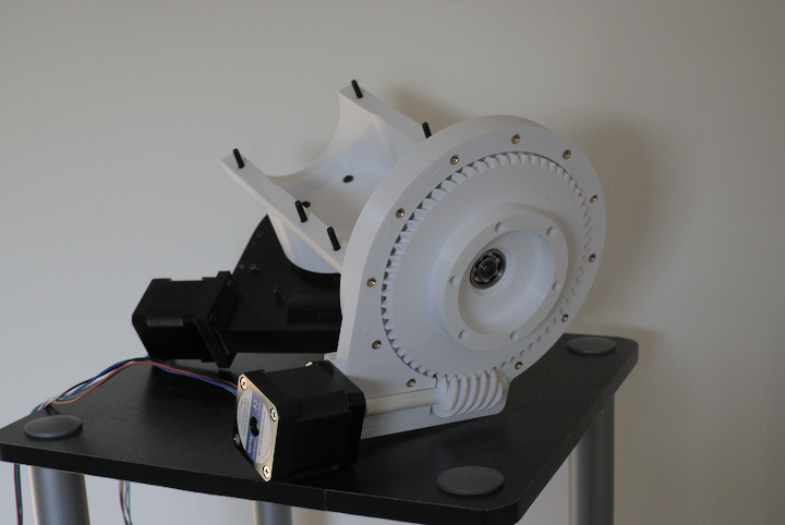
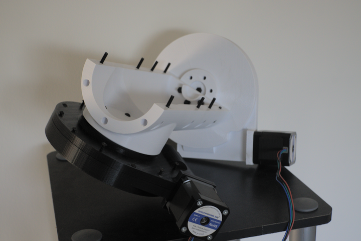
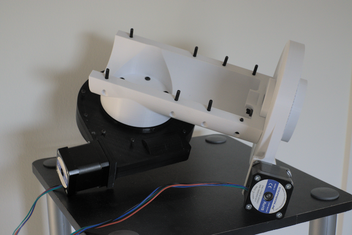
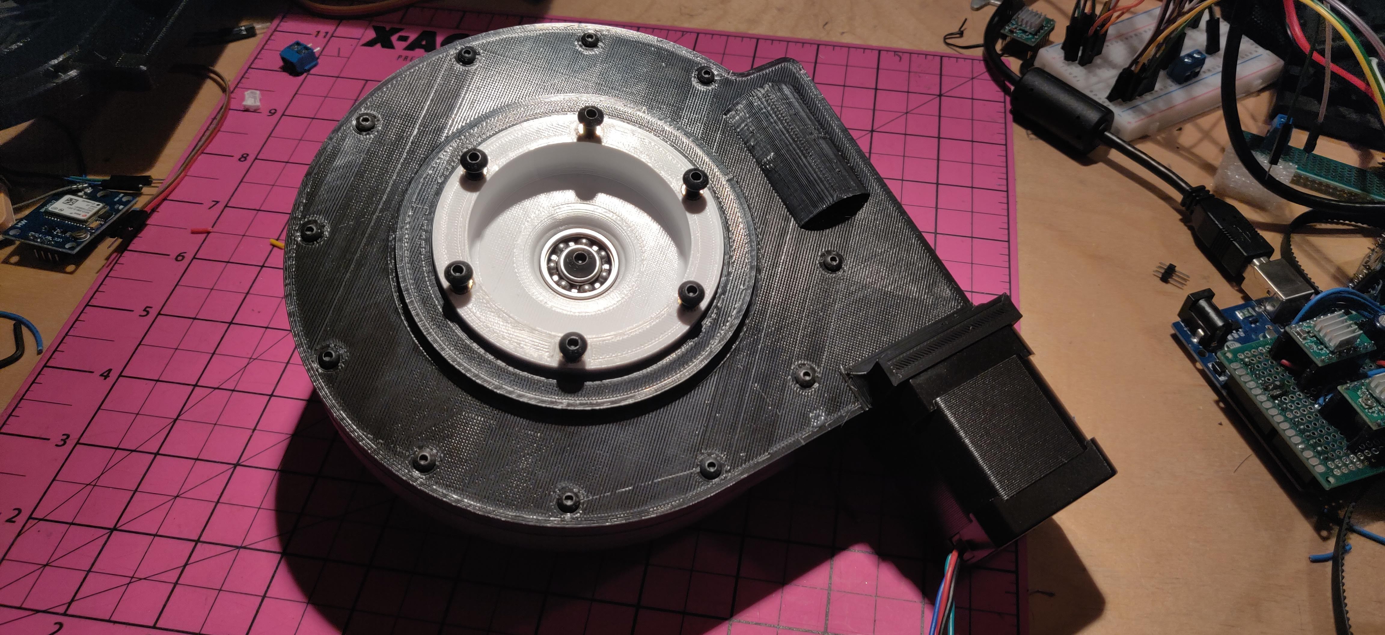
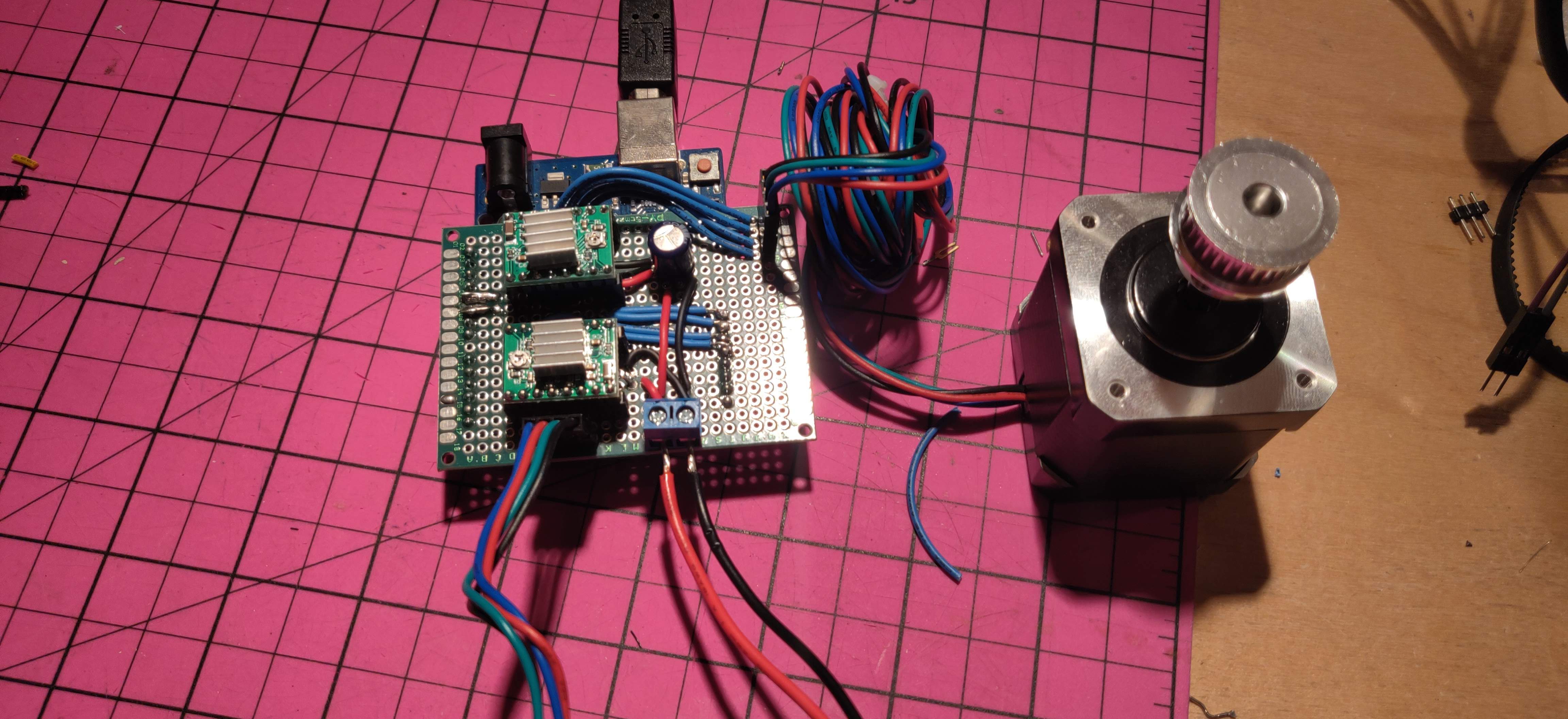
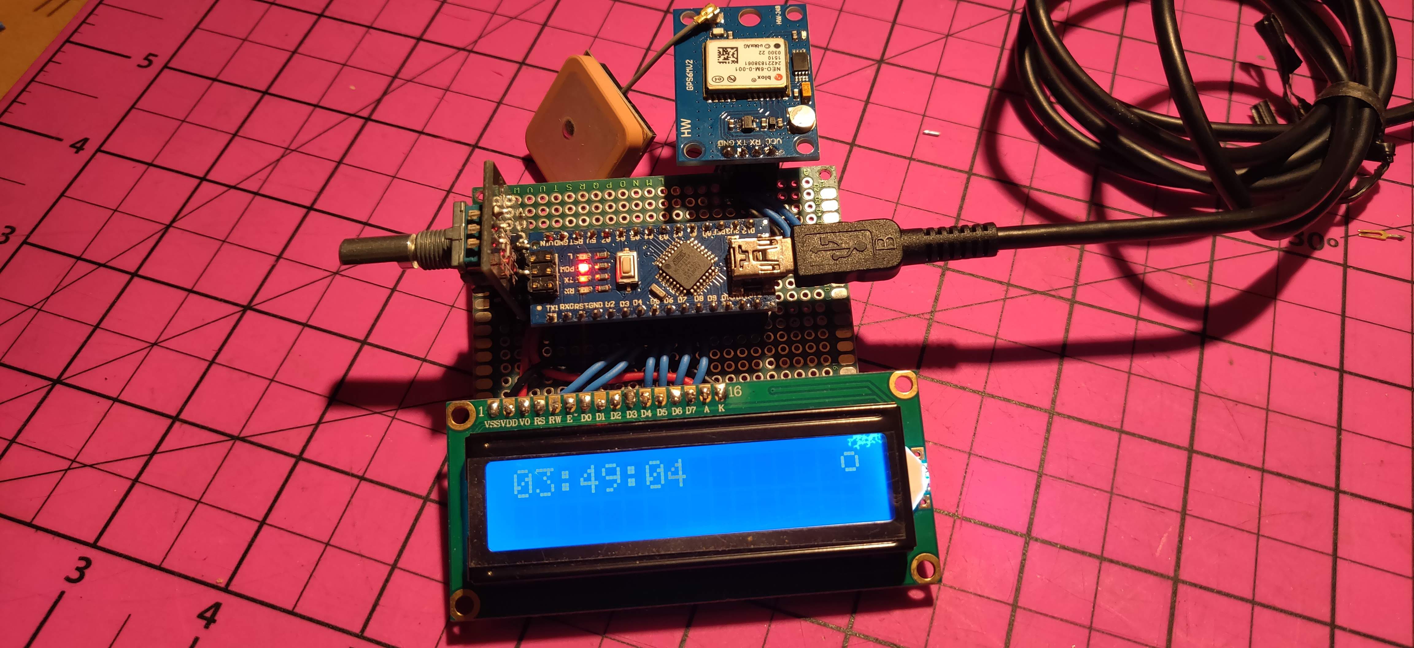
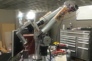
The Star Tracking Arduino (STAr) will be an all inclusive star tracking Alt/Az mount and GoTo solution for cameras and telescopes.
 John Farrell
Become a Hackaday.io member
Already have an account? Log in.
Just one more thing
To make the experience fit your profile, pick a username and tell us what interests you.
Pick an awesome username
hackaday.io/
Your profile's URL: hackaday.io/username. Max 25 alphanumeric characters.
Pick a few interests
Projects that share your interests
People that share your interests
 Colin Kingsbury
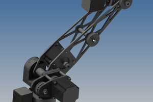
 Andrew Becker
 Oscar S.
 Mike Maluk