Close
0%
0%

LG SJ2 Sound Bar hack

The LG SJ2 sound bar comes with the SPJ2BW wireless active subwoofer. This shows how to hack the woofer to provide 2.1 stereo and more.

Similar projects worth following
The SJ2 is a basic sound bar with wireless sub woofer. Being a basic sound bar there is no control over the sound quality from the sound bar speakers and although it is good it has the potential to be better. The system comes with a SPJ2BW wireless active subwoofer which is where the hack is performed.

Opening the subwoofer there is a single pcb with power supply, speaker driver and a pigyback wireless module. Interestingly there is a connector with 3.3V power and I2C pins connected.

Removing the large heatsink from the power amplifier IC it turns out to be an ESMT AD3586B.
Investigating the IC it turns out to be an I2C controlled power amplifier, equalizer, volume control ic with various output configurations for mono, stereo and 2.1 stereo (and more...). The datasheet is readily available on the internet to download.

In its standard LG configuration it is configured as a single mono output to drive the single speaker.

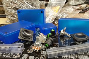
After studying the datasheet it seems easily possible to re-configure it to run 3 speakers in it's 2.1 mode.  This involves very carefully lifting one of the configuration pins and tying it to 3.3V. Then 6 of the ferrite beads need to be re-positioned and re-cabled to output sockets for left and right and a jumper wire added to re-connect the now disconnected bass speaker output (all can be seen in the photos).

Using a Saleae logic probe with the I2C analyser the commands that are sent to the AD3586B can be decoded. The AD83586 is at I2C address 0x6a, there is also a 24C128 EEPROM on the wireless daughter board that appears to be at address 0x0a.

It turns out there are several sequences sent, both on power up (when graphic equalizer filters are set) and for volume up, down, mute, bass boost.

The IC also incorporates a surround sound function and bass/treble boost/cut (none of which are used by LG). Also there are individual volume controls for the 3 channels and a master volume control. There is a 20 band equalizer, DRC controls, mixers and various other features that I have yet to explore..

In the basic re-configured state there is very little that can be heard from the speakers as the volume level is adjusted for a 60W output and we now have 2 x 20W + 1 x 40W. The IC needs to be set up to correctly function in its new configuration.

To run the 'new' speaker I use a Wemos ESP8266 module as this allows me to connect wirelessly to the speaker and adjust parameters via a web browser.  The software is still a work in progress but is posted here for anyone who wants to play with it.

One thing still evades me (if anyone fancies taking up the challenge!). The user-defined equalizer.. I can't figure it out. Page 51 of the datasheet does, in my opinion, a pretty poor job of explaining it with zero examples - anyone any good at parametric transfer functions?

Transfer functions aside, it works and I'm reasonably happy with the results. I'll keep tweaking the software but the hardware side seems pretty much sorted.

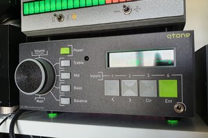
The soundbar can be controlled from its own web page which contains a number of sliders for volume, bass, treble, equalizer settings and settings for surround sound, equalizer bypass etc. These are the control settings for State control 4.

The software includes ssdp discovery so when it is connected to your network it will appear as LG Sound Bar in the 'Home automation' collection.

There is also a debug output so you can see some of what is going on when you change settings. The debug screen can be accessed via http://<your ip address>/debug.html

webpage.png

Web page for configuration and control

Portable Network Graphics (PNG) - 39.15 kB - 10/20/2019 at 09:56

Preview
Download

  • 1 × Wemos ESP8266 module
  • 4 × 1n2 capacitors
  • 2 × RCA connector sockets
  • 2 × RCA plugs
  • 1 × Shielded audio cable

  • Changes and updates

    Acuario10/20/2019 at 09:51 0 comments

    20-October

    • Studying the initial startup data I identified a number of pre-defined coefficient strings in the data, most of which are used but a couple that aren't. I added these to the main web page and made them easily selectable for testing. The coefficient strings are now uploaded in one go and set the selected EQ.
    • When the subwoofer is powered down (by the main bar switching to standby), on reactivating any settings are lost (volume) presumably due to the master volume and ch1 volume being reset by the LG CPU. I added a 1 second timer to constantly refresh the volume values so this should override the LG settings.

View project log

  • 1
    Changing the operating mode to 2.1 and re-configuring the speaker outputs

    The LG unit is configured as a mono output. To change the configuration to 2.1 stereo you need to connect pin 5 (CFG1) to 3.3V. This is a very fiddly job owing to the size of the IC. I used a very finely ground screwdriver tip to dig under the pin (no heat involved) and managed to lift the pin from its solder pad. I then used a very fine point soldering iron and solder paste to solder a wire from the pin to the +3.3V supply track to the IC (see photo).

    Also, you need to lift and re-position 6 of the ferrite beads, 4 for the left and right speakers and 2 for the woofer. The other 2 for the woofer can be left in place. Then connect a jumper wire from the lifted 2 woofer outputs to the now disconnected track where the woofer was connected (see photo).

  • 2
    Speaker outputs

    In my case I did not modify the LG chipboard box as I managed to squeeze 2 x RCA connectors into the space below the power lead input. There are 1.2nF capacitors connected between the + and - outputs of both speaker outputs to the unit 0V.  Shielded cables are connected from the speaker outputs to the tops of the ferrite beads that are now the left and right outputs. (see photo).

  • 3
    Mounting the ESP8266

    I use a Wemos ESP8266 board mounted on a small piece of veroboard to connect the ESP8266 to the relevant pins on the mainboard I2C connector.  In my case I use GPIO12 and GPIO13 (SDA A4, SCL A5) for my interface.

View all 4 instructions

Enjoy this project?

Share

Discussions

Pelu Chie wrote 11/03/2022 at 10:41 point

how can i add analog input to this subwoofer like 3.5mm headphome jack?

  Are you sure? yes | no

Lexi777 wrote 04/25/2021 at 21:12 point

Nice work. I will surely try this hack with my sound bar system which I bought by reading some reviews on blog,  you can see here https://systemsoundbar.com/best-5-1-soundbars/

  Are you sure? yes | no

Mike Szczys wrote 10/29/2019 at 21:57 point

Great find on unlocking these features. It's incredible to think you can install a single-module hack like this and then tweak registers through the web interface. Nice hack!

  Are you sure? yes | no

Similar Projects

Does this project spark your interest?

Become a member to follow this project and never miss any updates