 Ced
CedThe decoder section of the architecture diagram shows a 13-bit decoder register.:
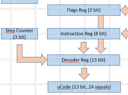
What is the rationale behind the need for this register?
In order to properly set the action signals, there is a need for 13 bits to address de EEPROM used to implement the micro-code:
- 3 bits for the steps (count from 0 to 7 steps maximum, however most macro-instructions will only need 3 or 4 steps)
- 8 bits for the instructions (not all 256 capabilities will be used)
- 2 bits for a combination based on the flags register
However, when looking at the specs of the EEPROM (AT28C64) we can see that in the worst case, between the stabilization of the address inputs and the availability of proper stable output it can take up to 250ns. This means that if bits from the address are not stable the output might not be valid.
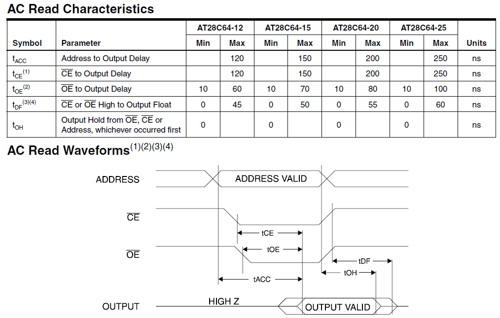
This is why the implementation of a register used to create a stable snapshot of the 13 bits will help providing stable action signals.
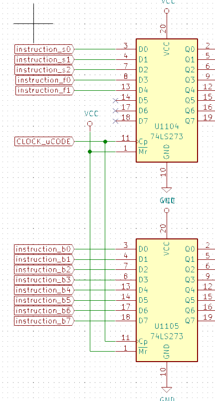
This is actually a perfect use case for the 74HCT273 register we already talked about. What we need is the capability to snapshot tu status of the 3 elements (register, steps, flags) at a given time and keep it stable until the next clock cycle:
Now the question is : when are values changed (step, instruction register, flags)? When in the overall instruction cycle are they stable enough that I can snapshot them ?
Well if we look at the clock cycle we can identify 3 moments:
- main clock (rising edge) : when the actions take place (add, load, etc)
- step clock : when the step is incremented
- uCode clock : when to hold the value of the 3 elements that constitute the micro-instruction register
So we need 3 clock rising edges per step cycle:
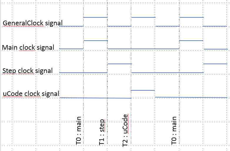
If the main clock signal is at 1Mhz, we get 1ms between general clock rising edges. So that is:
- 500ns between T0 and T1
- 500ns between T1 and T2
- 1000ns between T2 and the next T0 which is more than enough to stabilize the EEPROM values
Discussions
Become a Hackaday.io Member
Create an account to leave a comment. Already have an account? Log In.