 Justin Scott
Disclaimer
Tube circuits contain LETHAL voltages! Don't try to build this stuff if you don't know what you're doing!
Concept
In the summer of 2014 I decided to build a vacuum tube stereo.
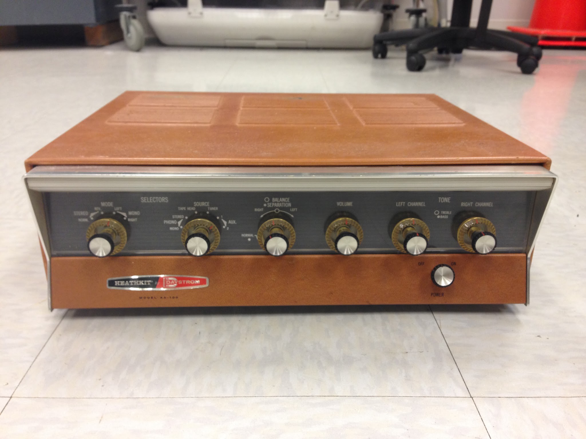
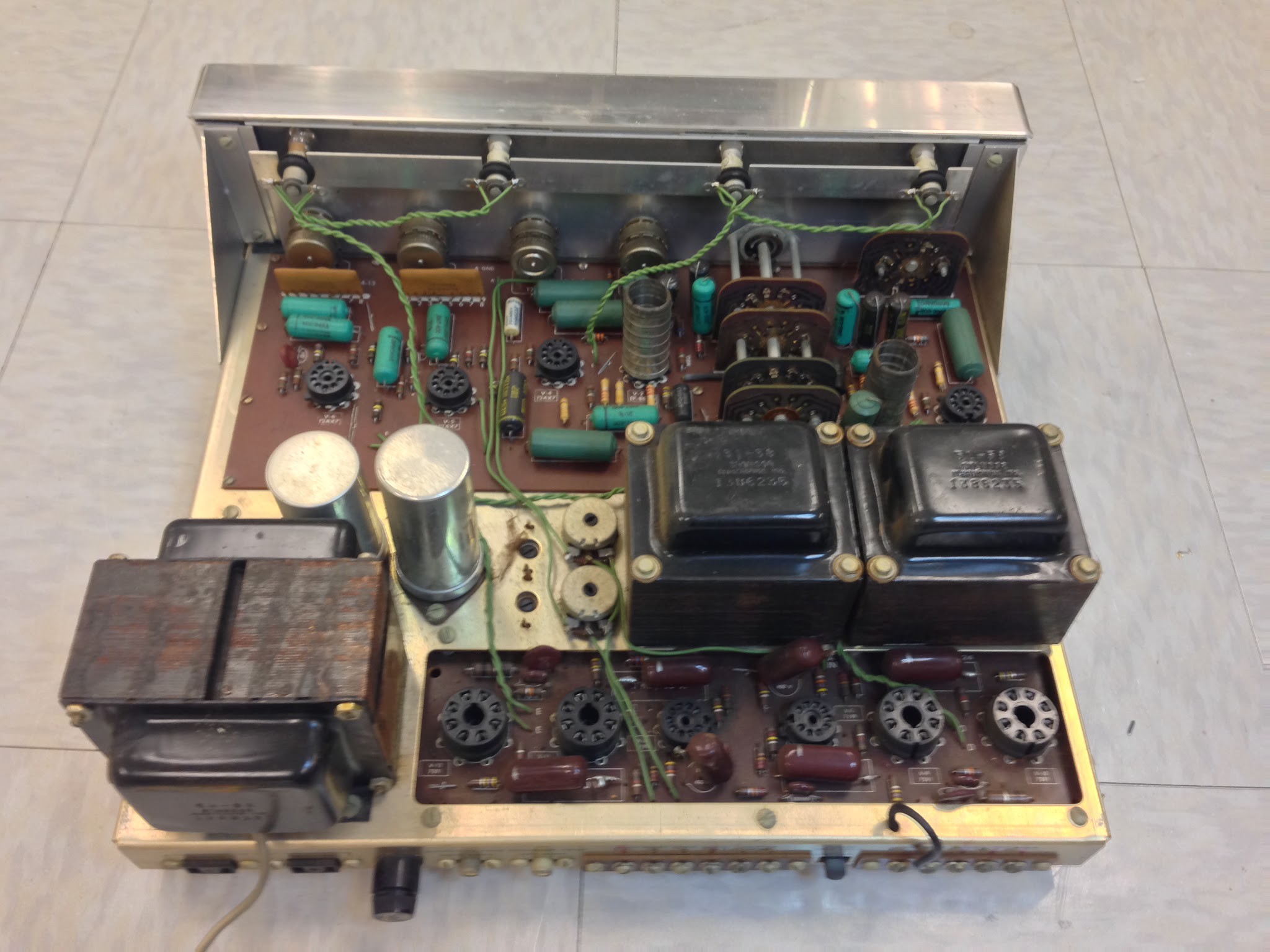
I had tried to find a Dynaco ST-70, the most popular tube stereo ever, to restore. But these are expensive, even in disrepair. A friend's dad had given me non-functional Heathkit AA-100, but I didn't like the look of the amp. It also doesn't have a reputation for great sound. So I decided to use the tubes and transformers (the expensive stuff) from the AA-100 to build a clone of an ST-70. I found a DIY amp builder named Tom McNally who had done the same thing in 2005.
Schematic
I started by drawing a schematic. There is a lot of information and parts online for ST-70s. Tom McNally had used a PCB from Parks Audio called the DIYTube ST-70 Driver for the input stage. I did as well. The output stage was taken directly from the Heathkit AA-100 schematic. For the power supply, I made my own PCB based on several designs for ST-70 kits I found online. For this I got some tips from Tom and the awesome folks at Audiokarma.org (a huge thank-you to dgillespie and kward). I simulated several sections of the circuit using LTSpice and PSUD2. The complete schematic is linked below.
Chassis
Next thing was the chassis. I knew I wanted some combo of wood and metal. I found photos of several amps online s inspiration:

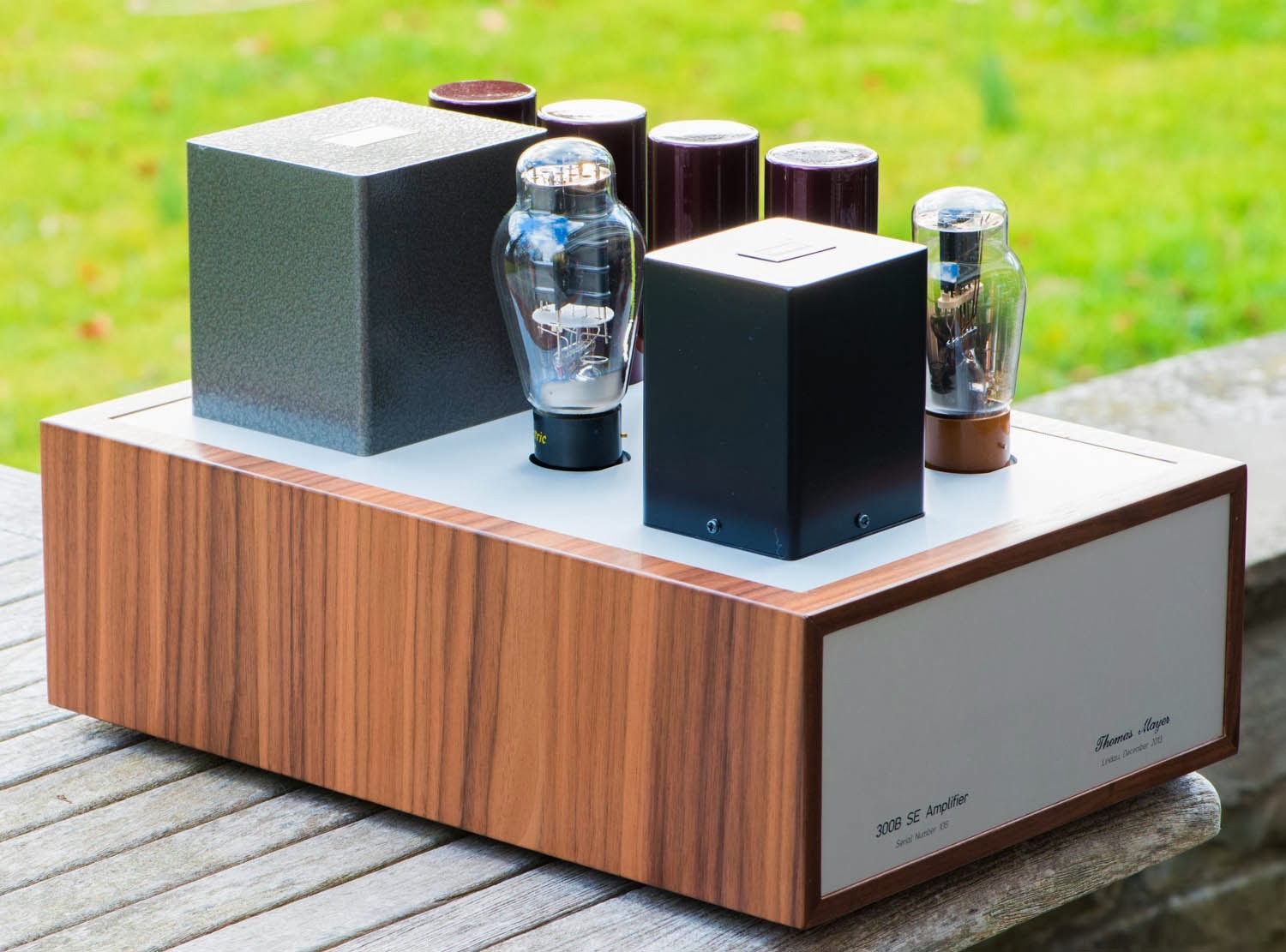

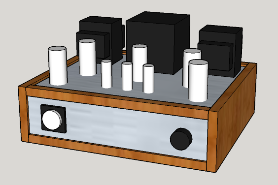
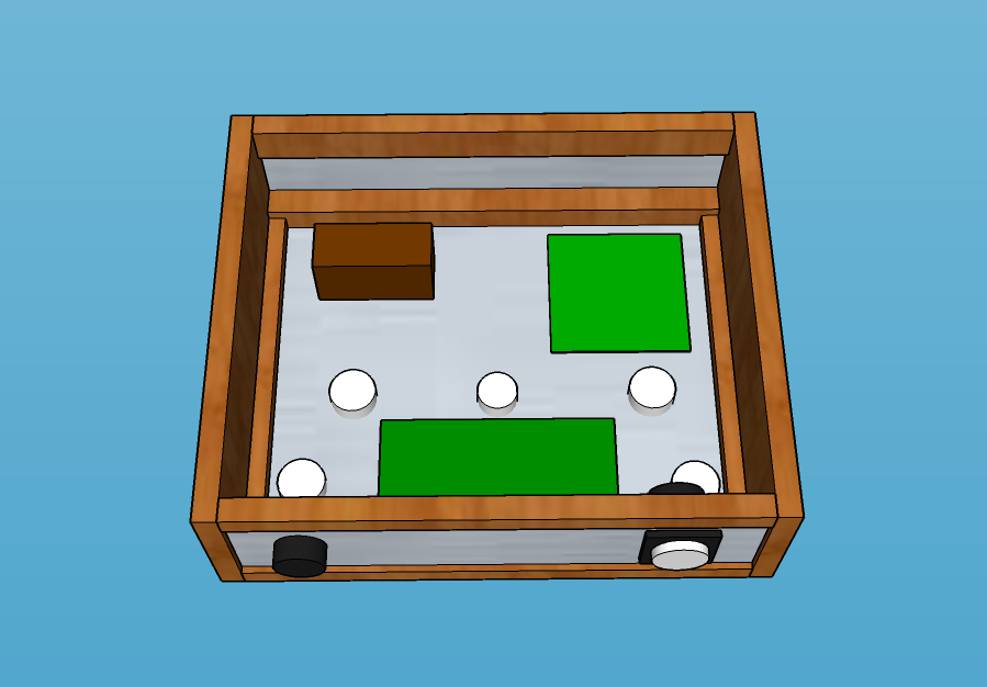
Using these as a starting point, I used Sketchup to create a model of the chassis. I decided to mount the output transformers on brackets instead of inset in the baseplate (like they were in the AA-100) to simplify the metalwork and free up space inside the chassis. Here are photos of the completed model (link below):

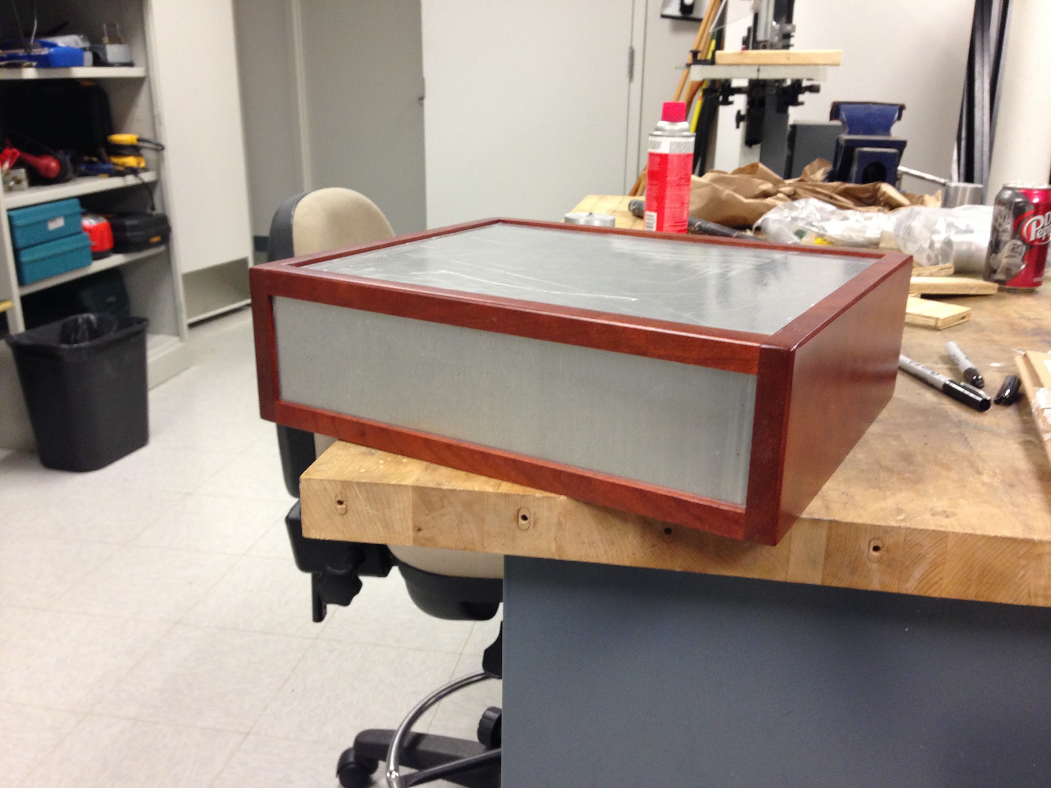
I am not a woodworker, but I have a father-in-law who is. He kindly agreed to build the wood part of the chassis. I sent him drawings; we made a few adjustments, and a few weeks later he emailed me this photo:
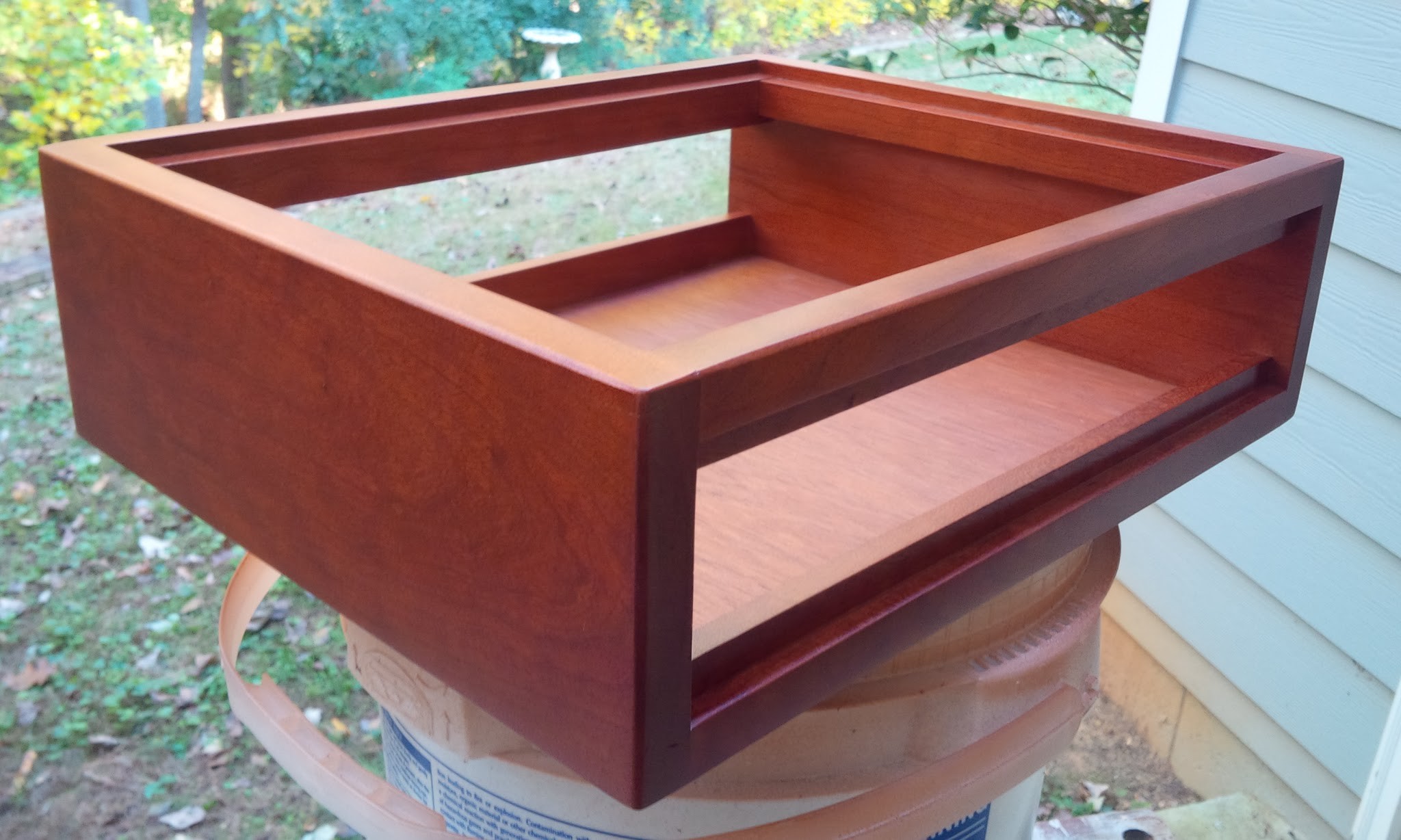
The wood is cherry. You can see how the finish darkens and deepens over time by comparing to the photos at the bottom of this post. The bottom panel is removable; I decided to remove it to aid convection.
Transformers
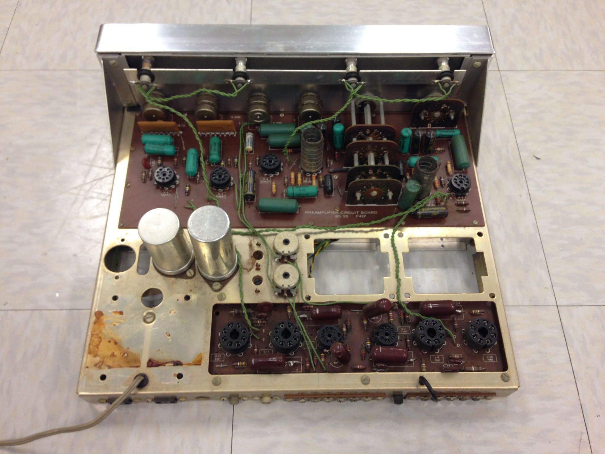
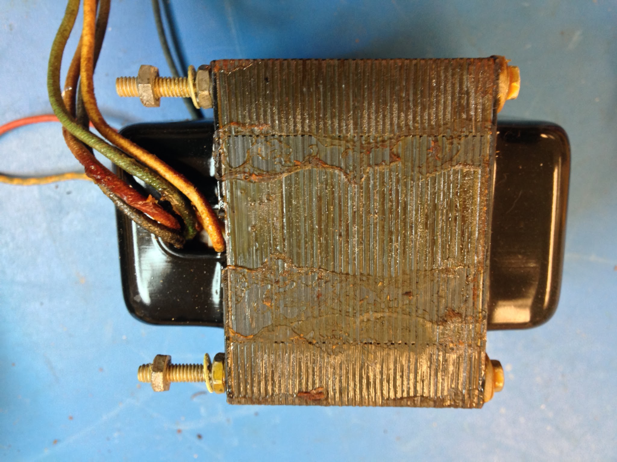
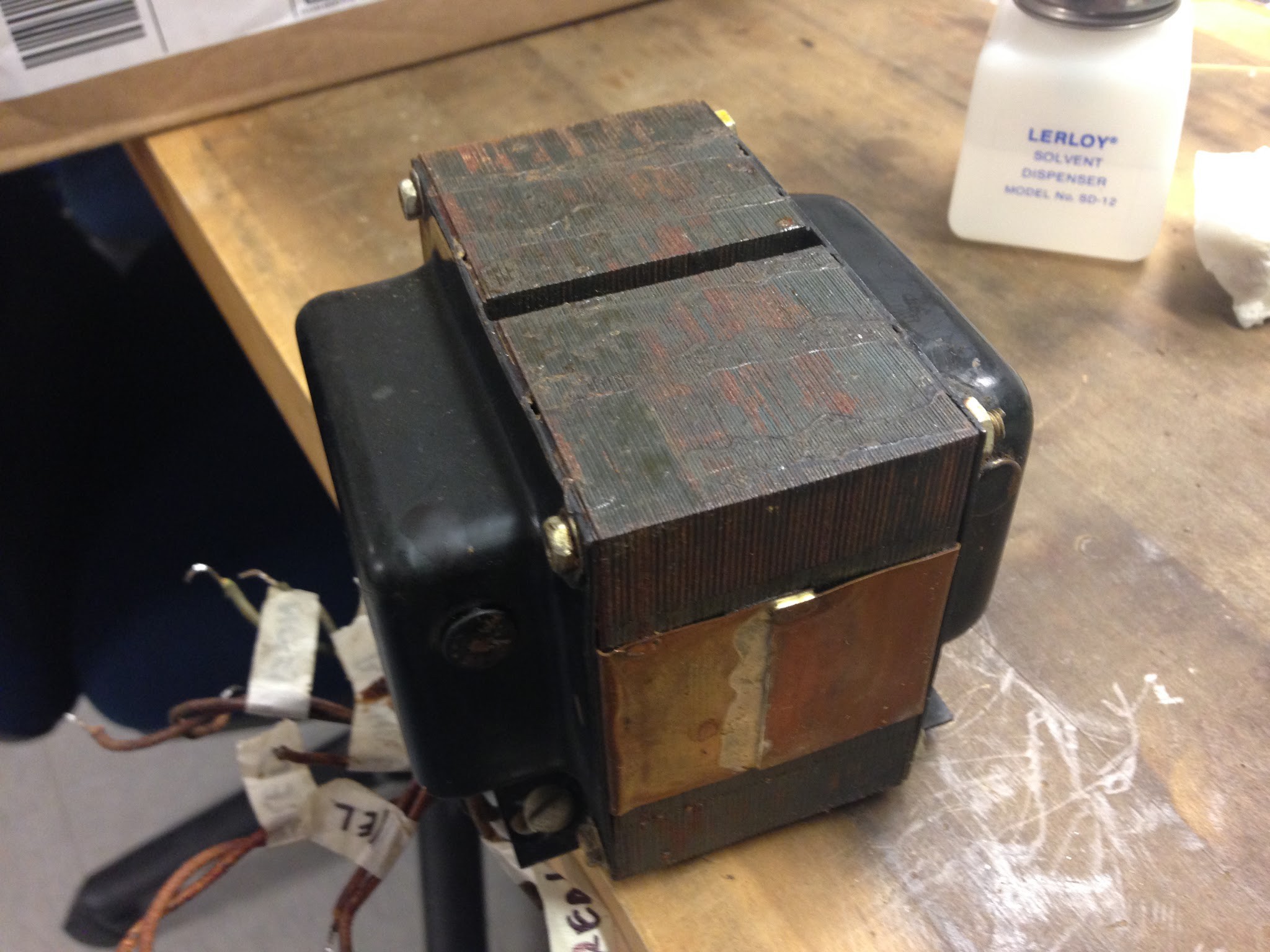
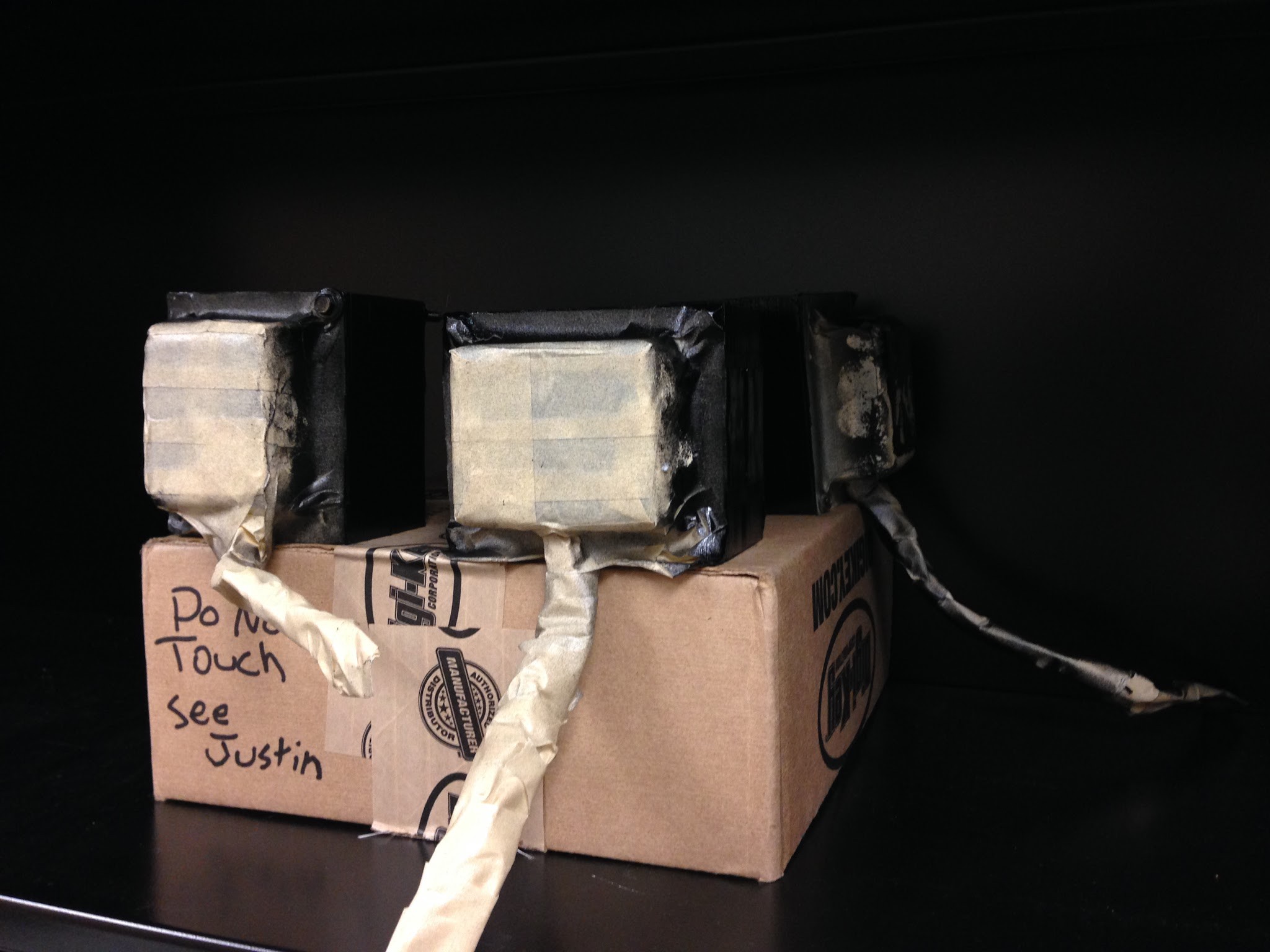
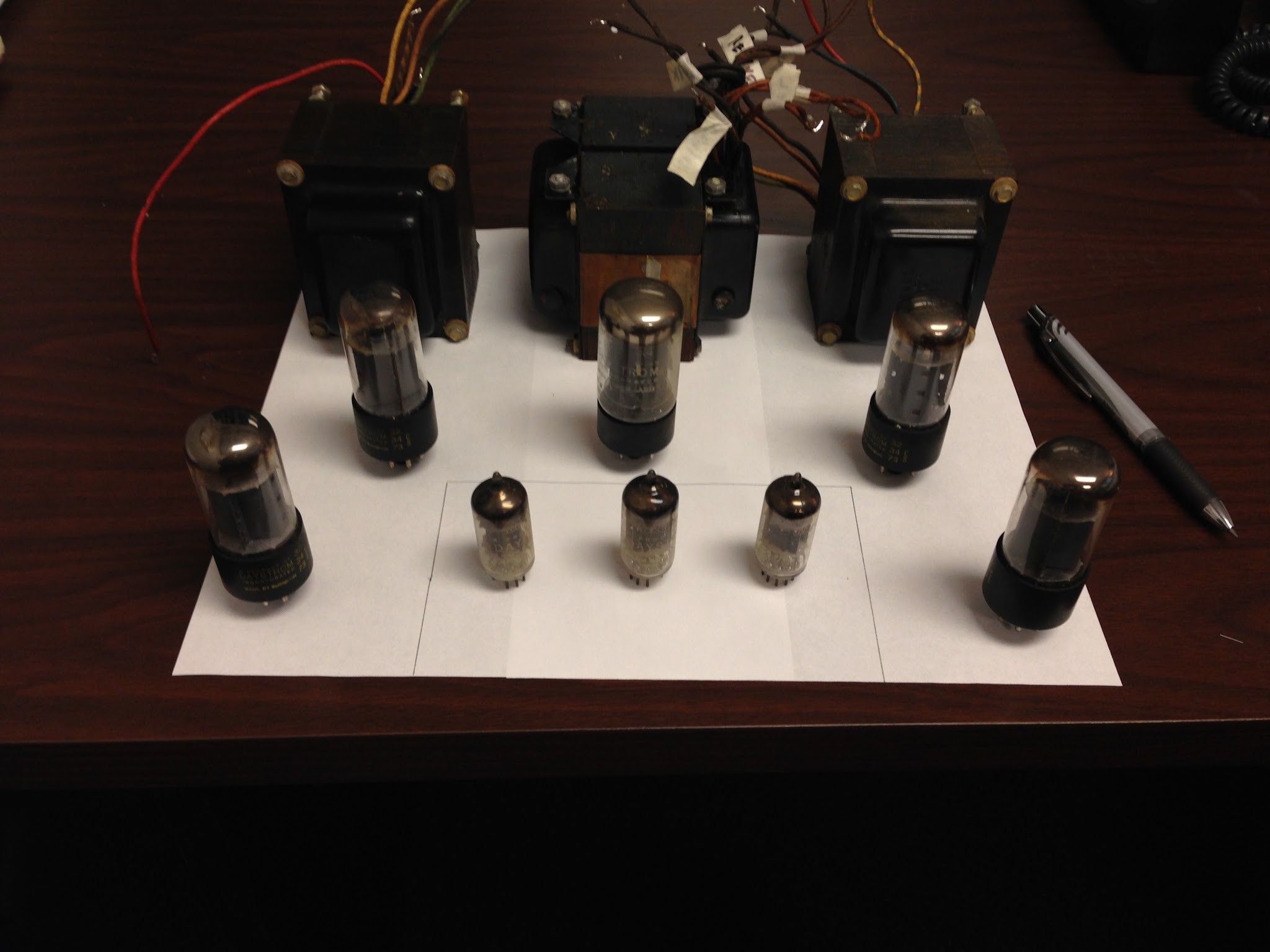
In the meantime I removed the transformers and fuse holder from my AA-100:
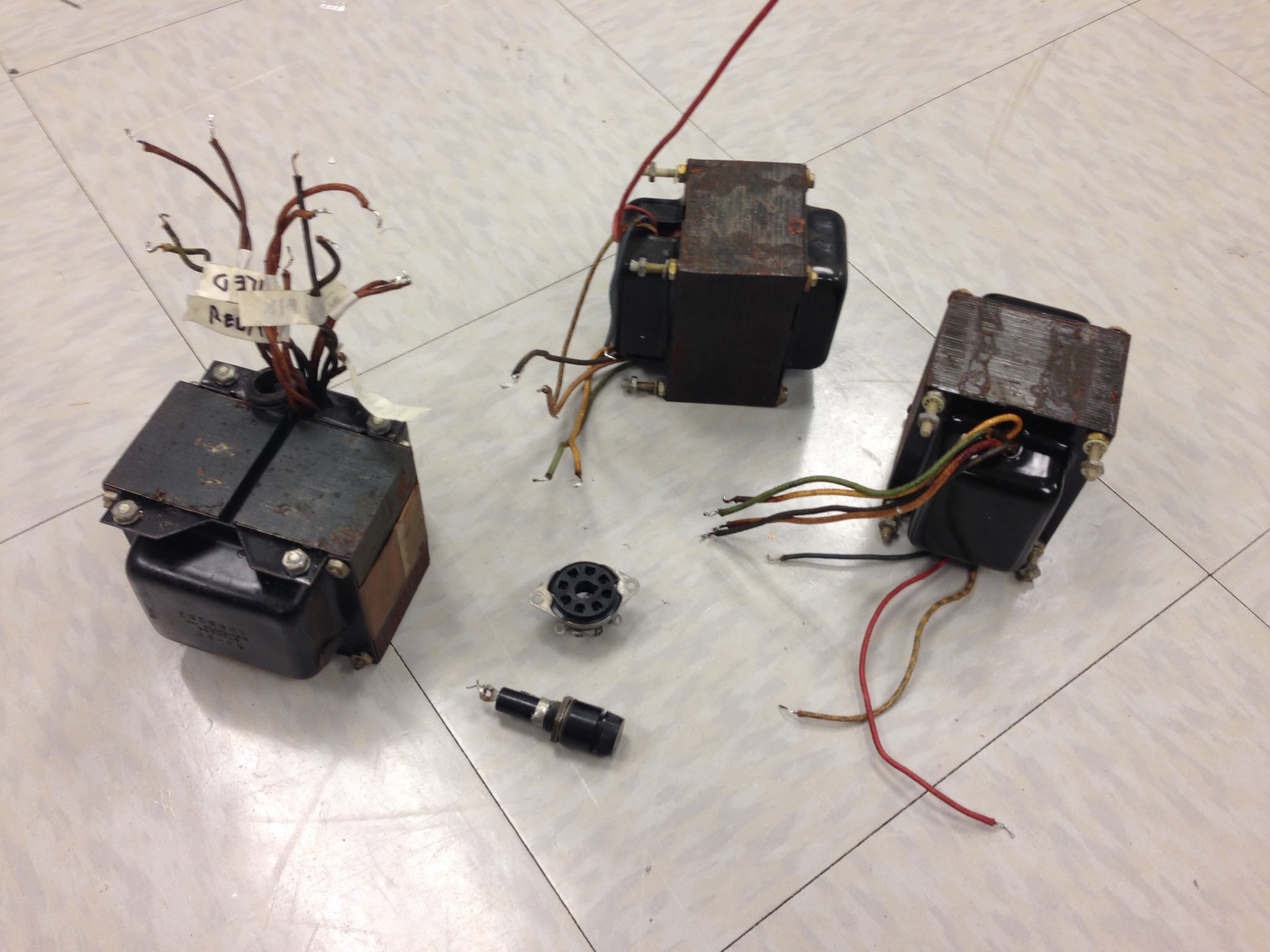
I discovered that the transformers were rusted and covered in wax, so I sanded and painted the cores with Rustoleum:
Metalwork
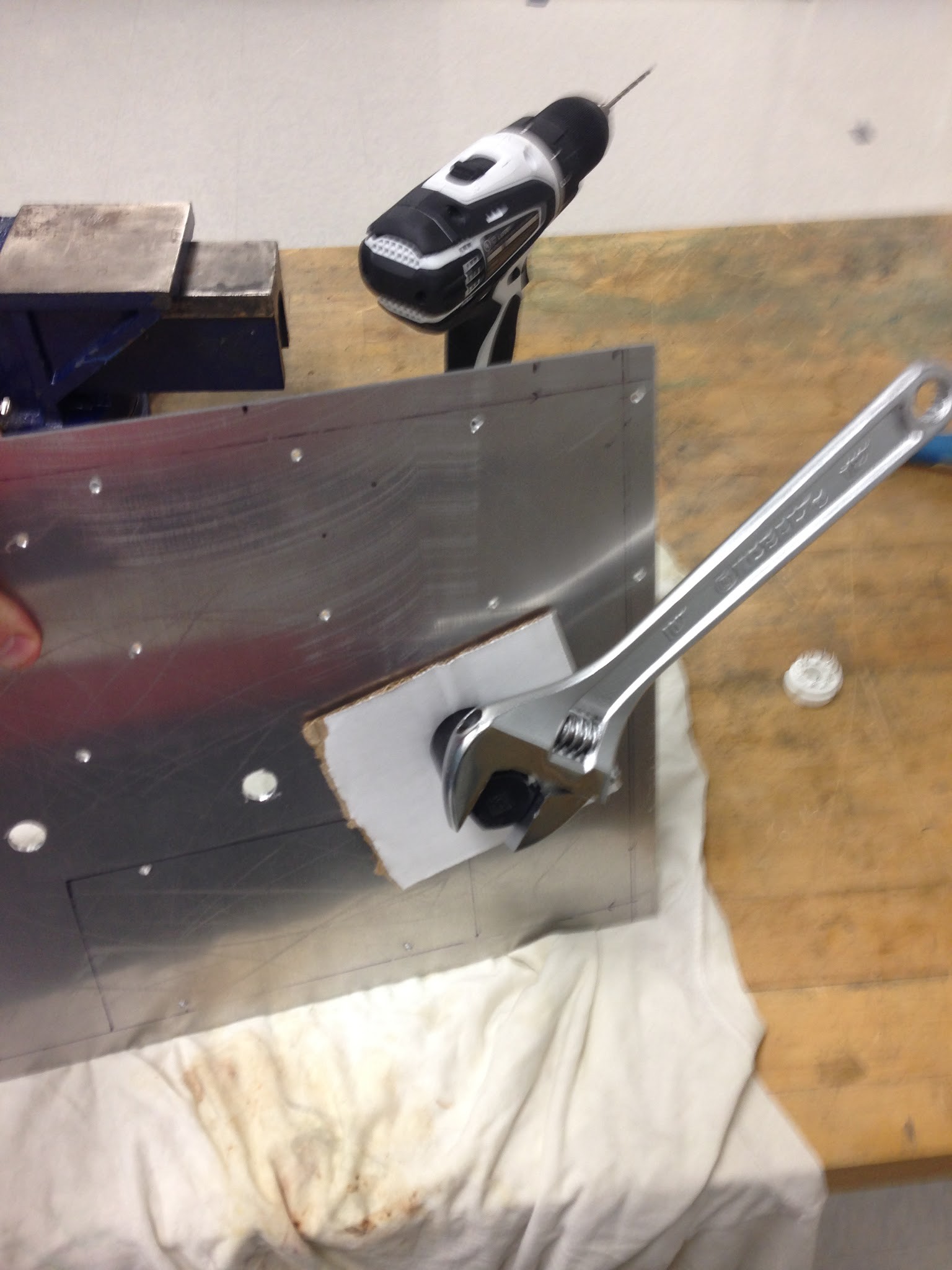
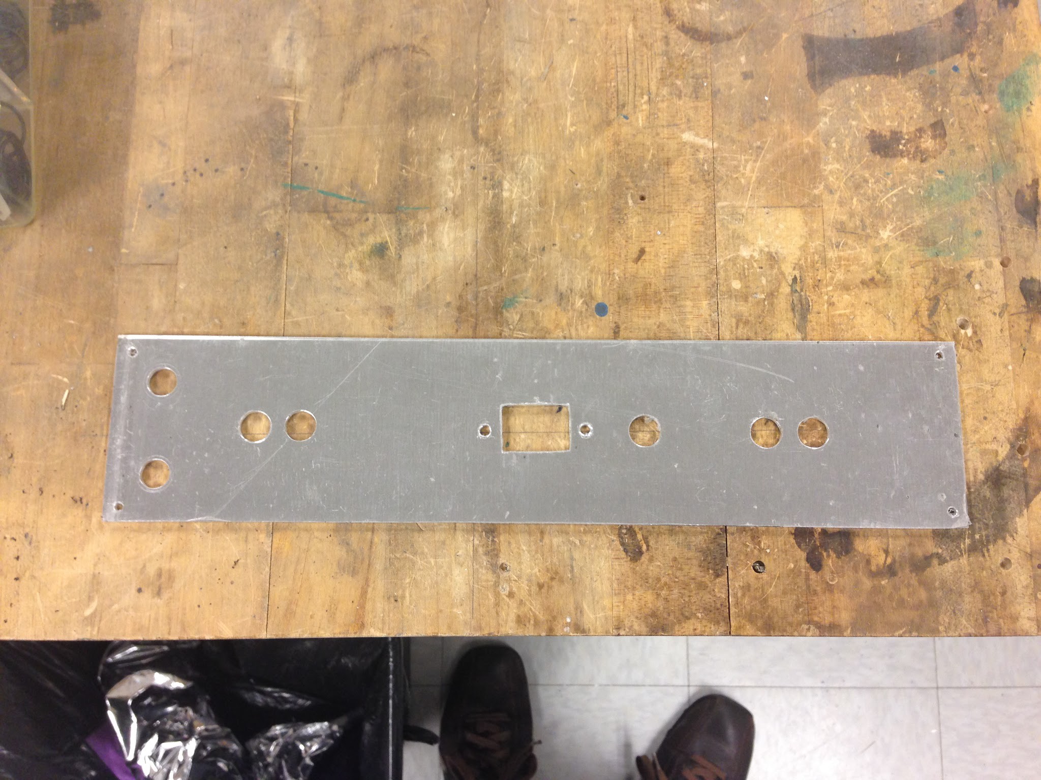
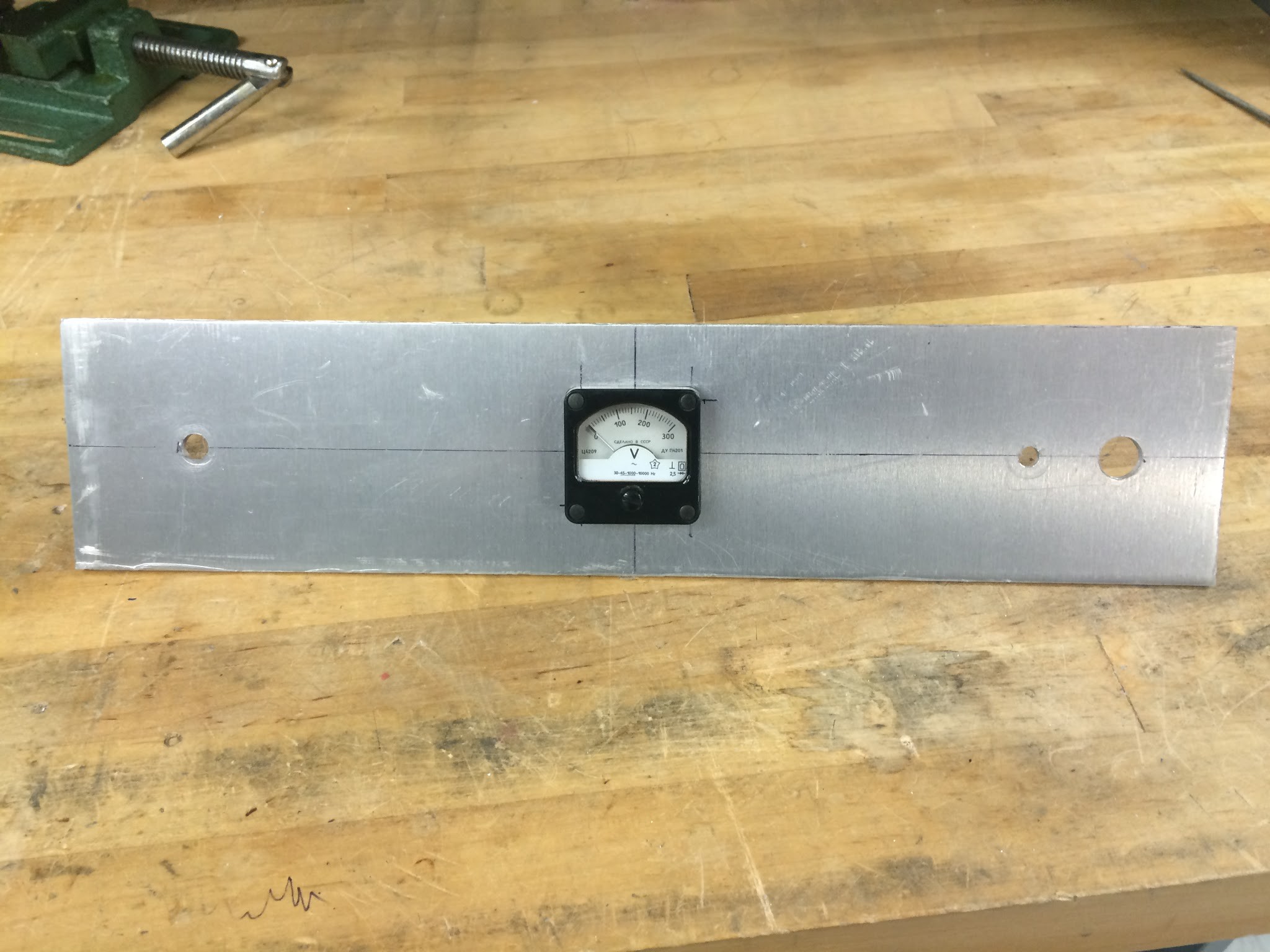
Next I ordered all the parts (a BOM is linked below), including three 1/8" aluminum sheets cut to size for the top, back, and front from onlinemetals.com. I then began the metalwork. Incidentally, this was the most painful part of the job, and if I had to do it again would spring for custom drilling. First I laid out the parts:
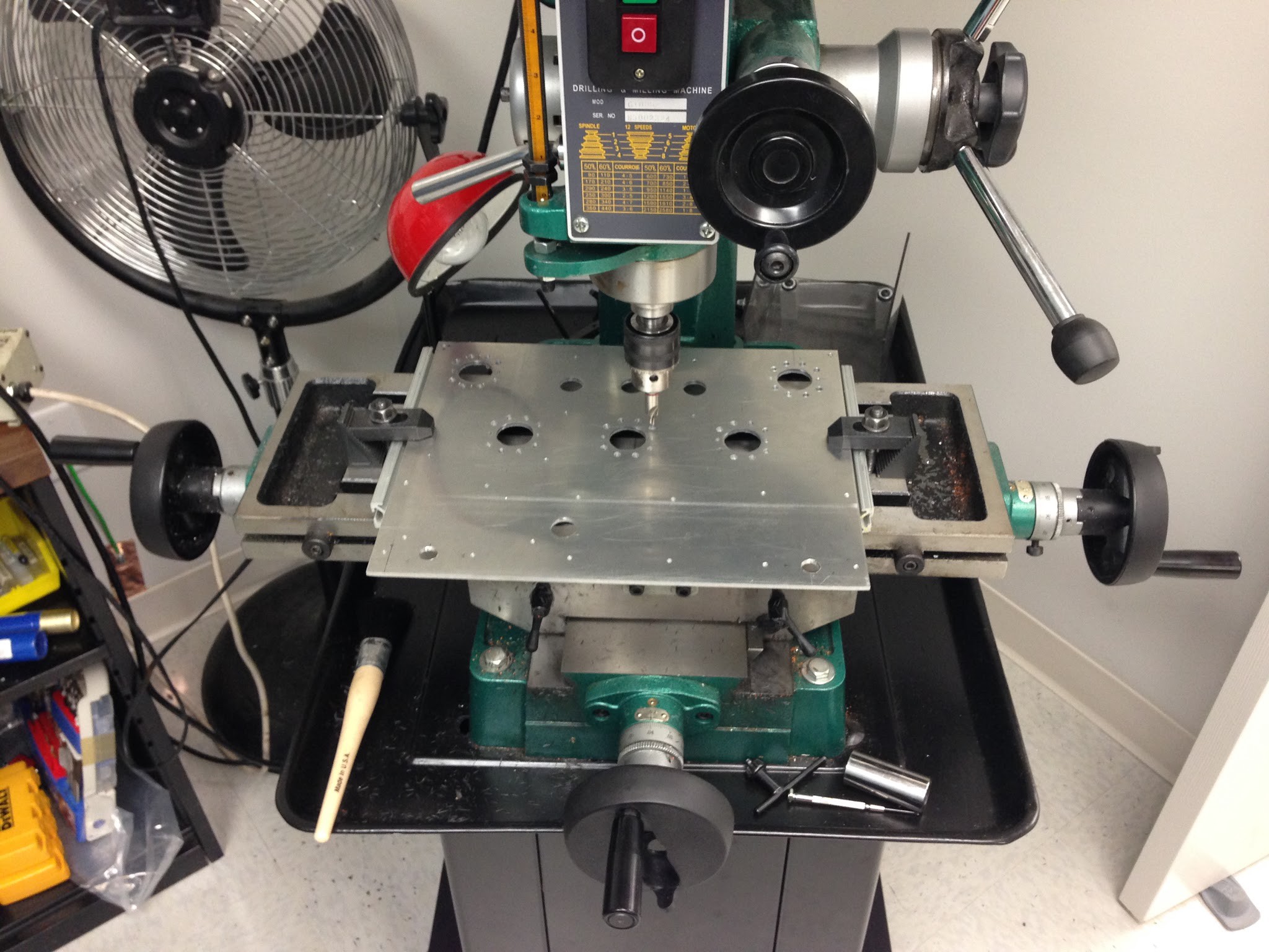
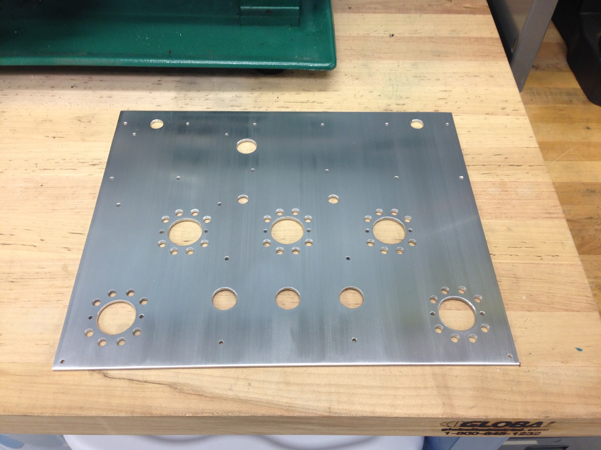
Then I drilled and punched:

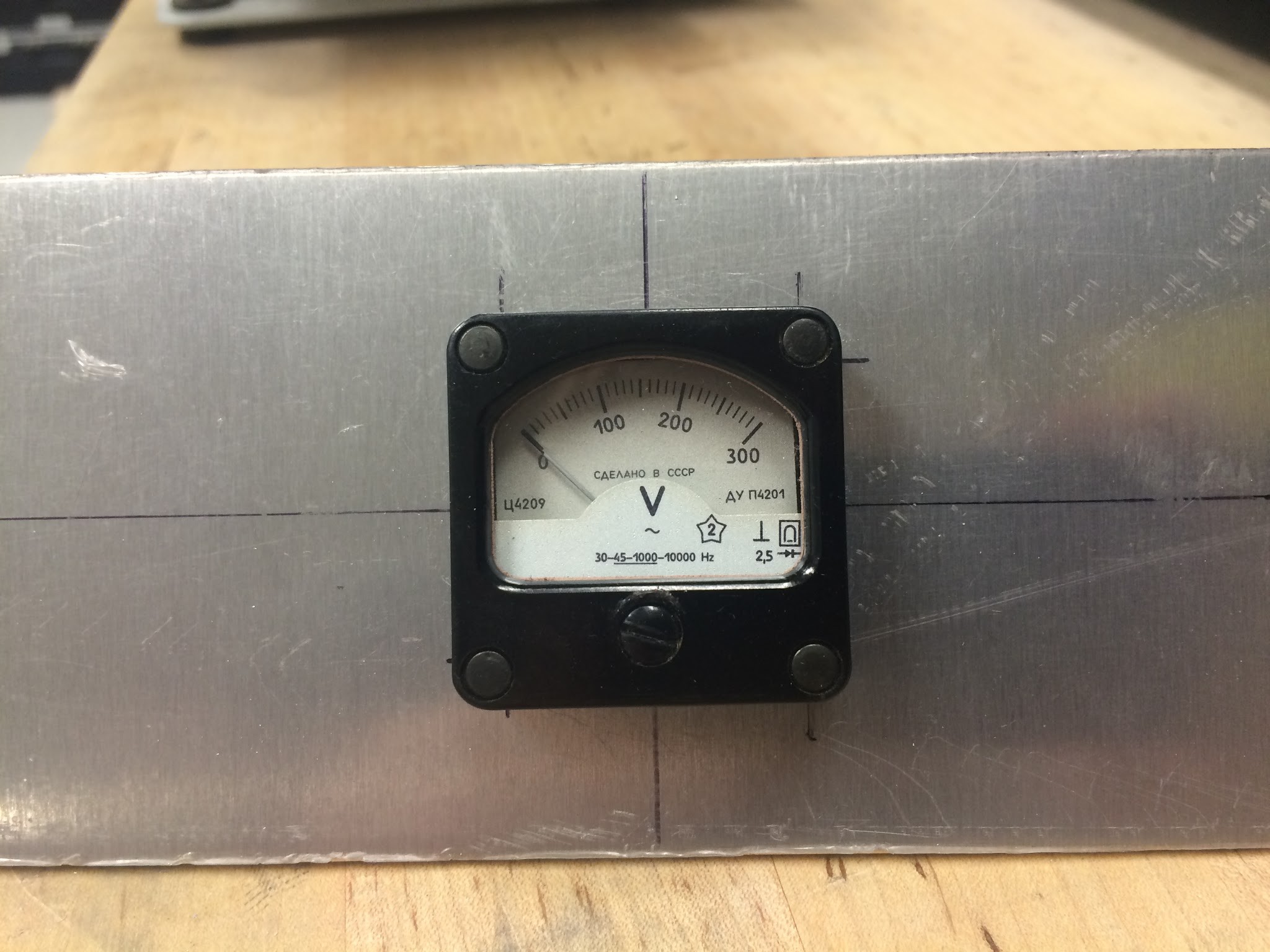
I am super-proud of this vintage meter I got on eBay. It was made in the USSR. I removed the rectifier so I could use it with DC voltage instead of AC.
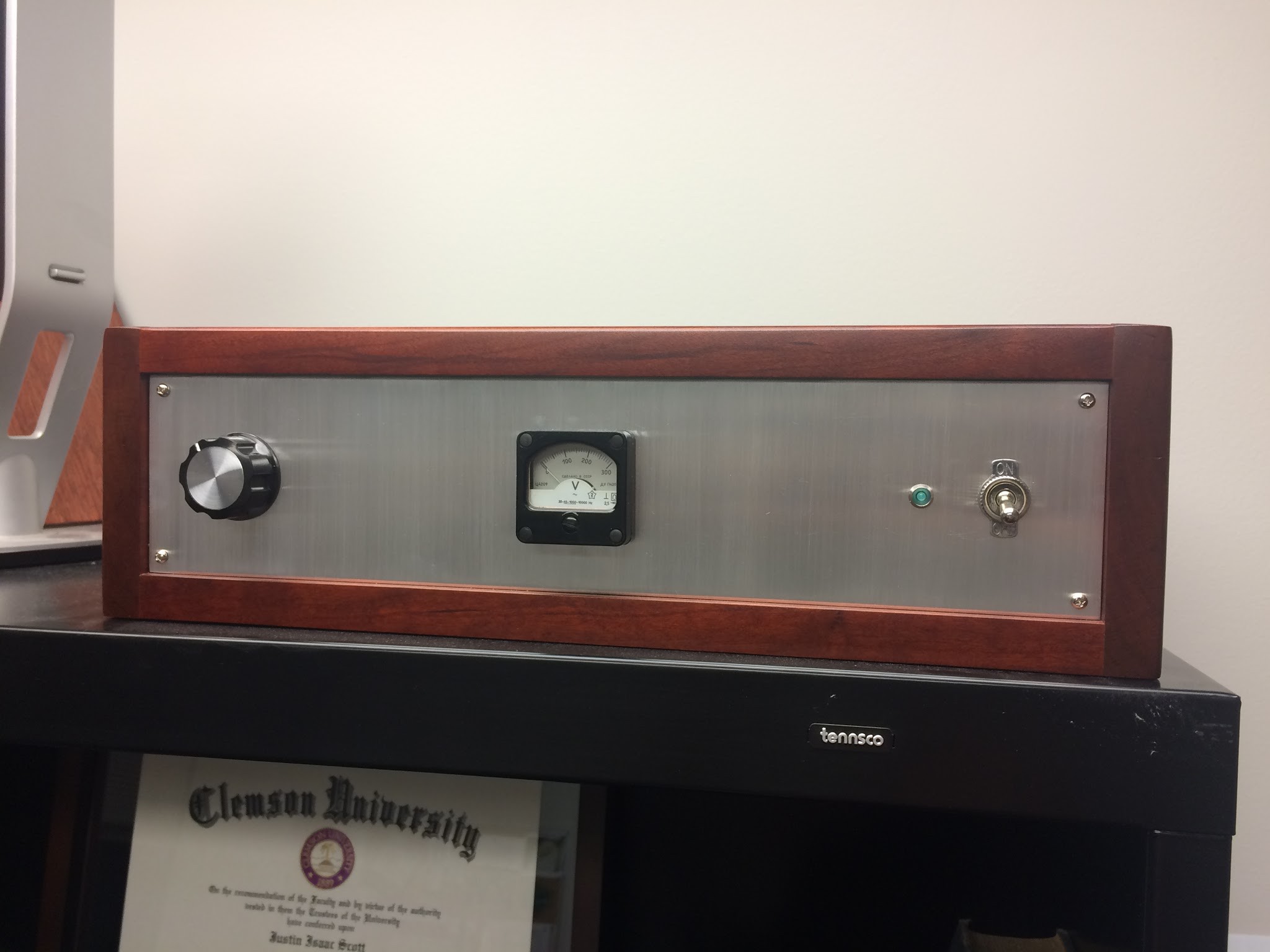
I wasn't happy with the look of this metal. The stock aluminum finish wasn't even and it was impossible to prevent a few dents and scratches. I found a tutorial online for brushing it by hand. It's a simple process: you brush the Al with 220 grit sandpaper using a guide block to make sure all the strokes go in the same direction. Then you brush it again with Scotchbrite to soften it. I was happy with the result:


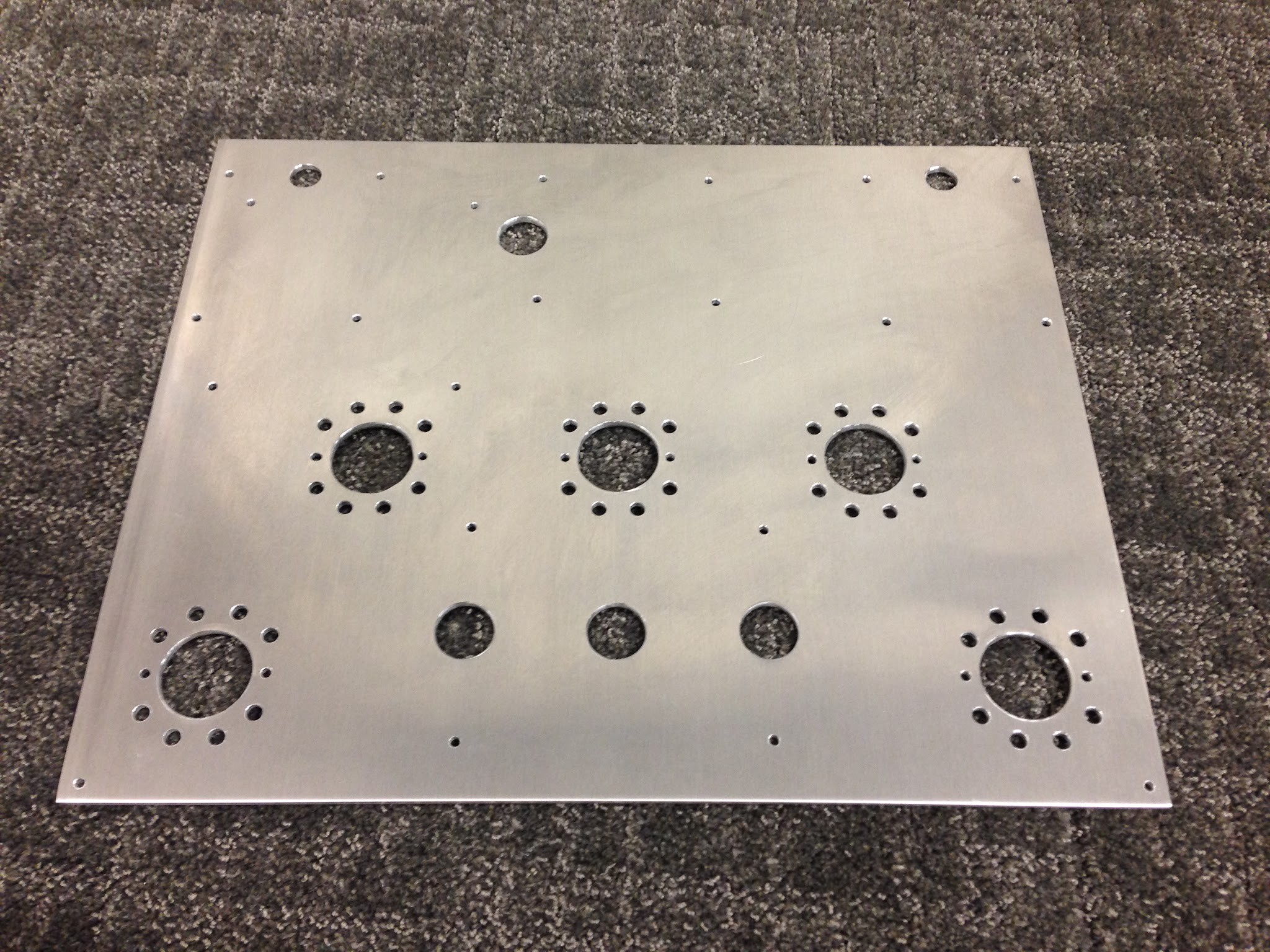
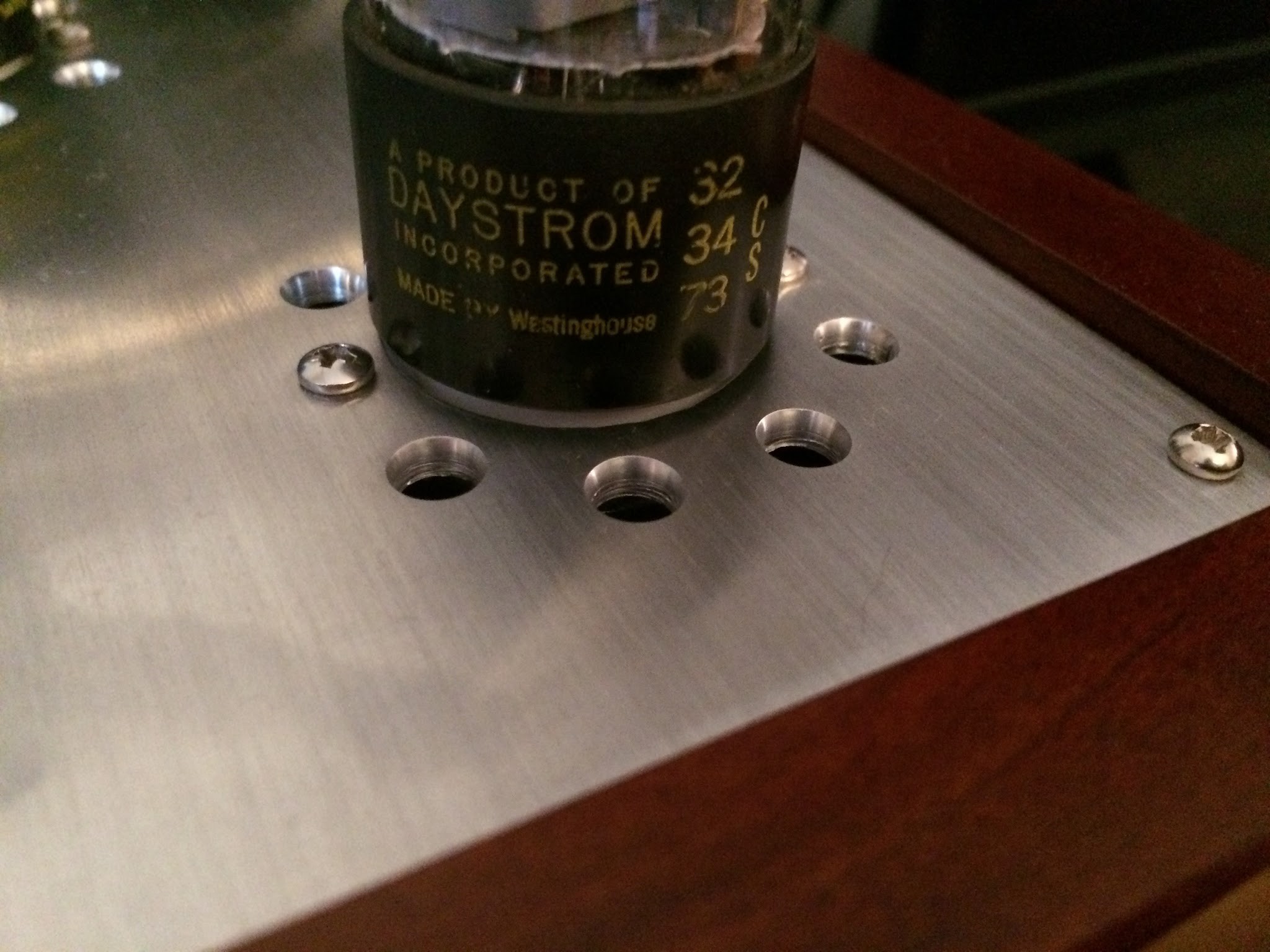
One other note: the vent holes around the tubes didn't look great after drilling and using a deburr tool. A mechanical engineer coworker suggested I pretty them up using a counter sink bit on our mill, setting the stop so I went to the same depth on each one. Here is the result:
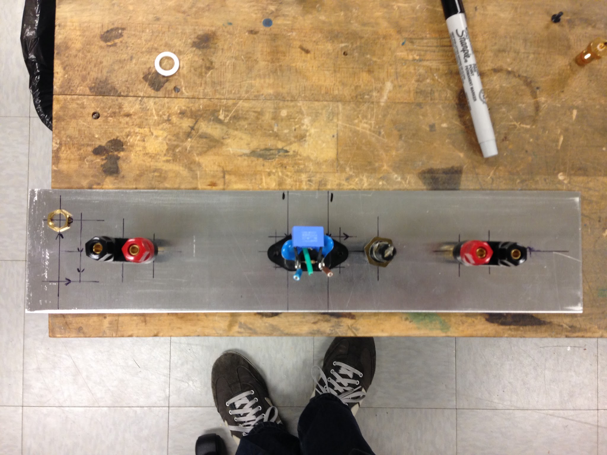
Wiring
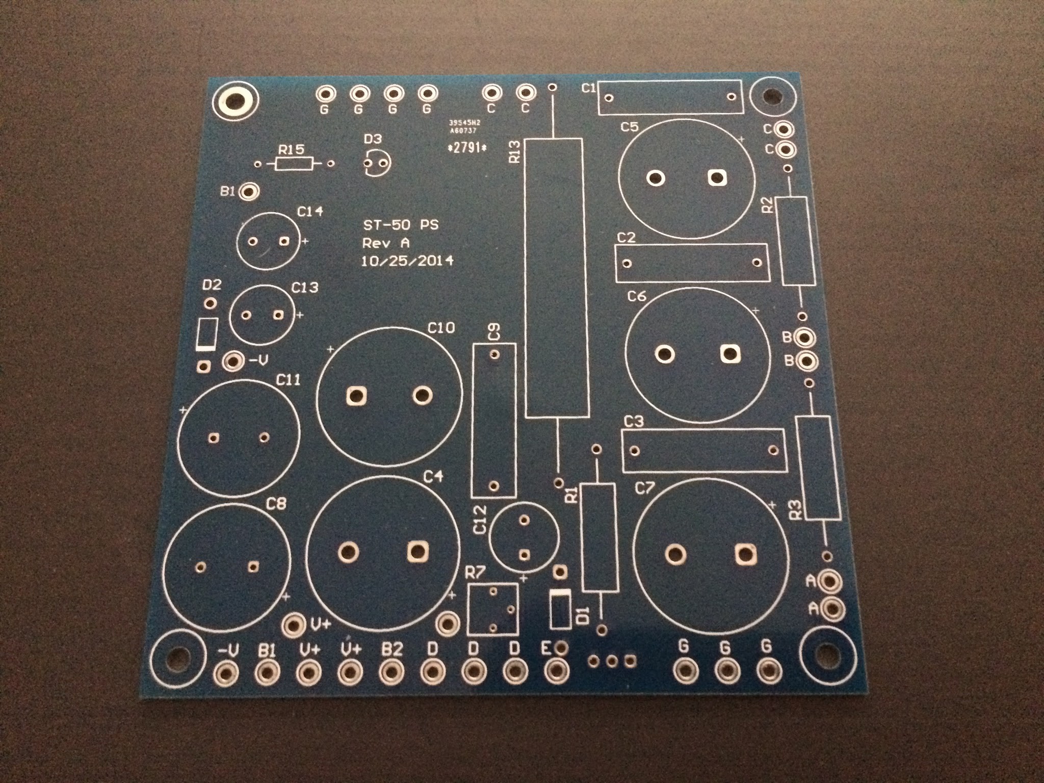
Next was wiring it up. Here is a photo of the PCB I designed for the power supply. I ordered it from dirtypcbs.com, which was the cheapest I could find despite getting 10 boards when I only needed one.
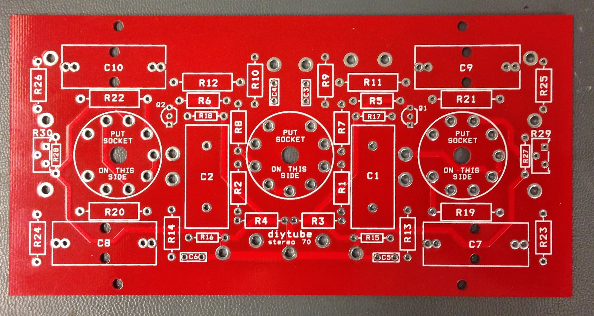
Here is a photo of the diytube ST-70 driver board:
First thing I wired was the tube heaters. Afterwards I powered up to make sure the heater voltage was right and everything glowed as expected.
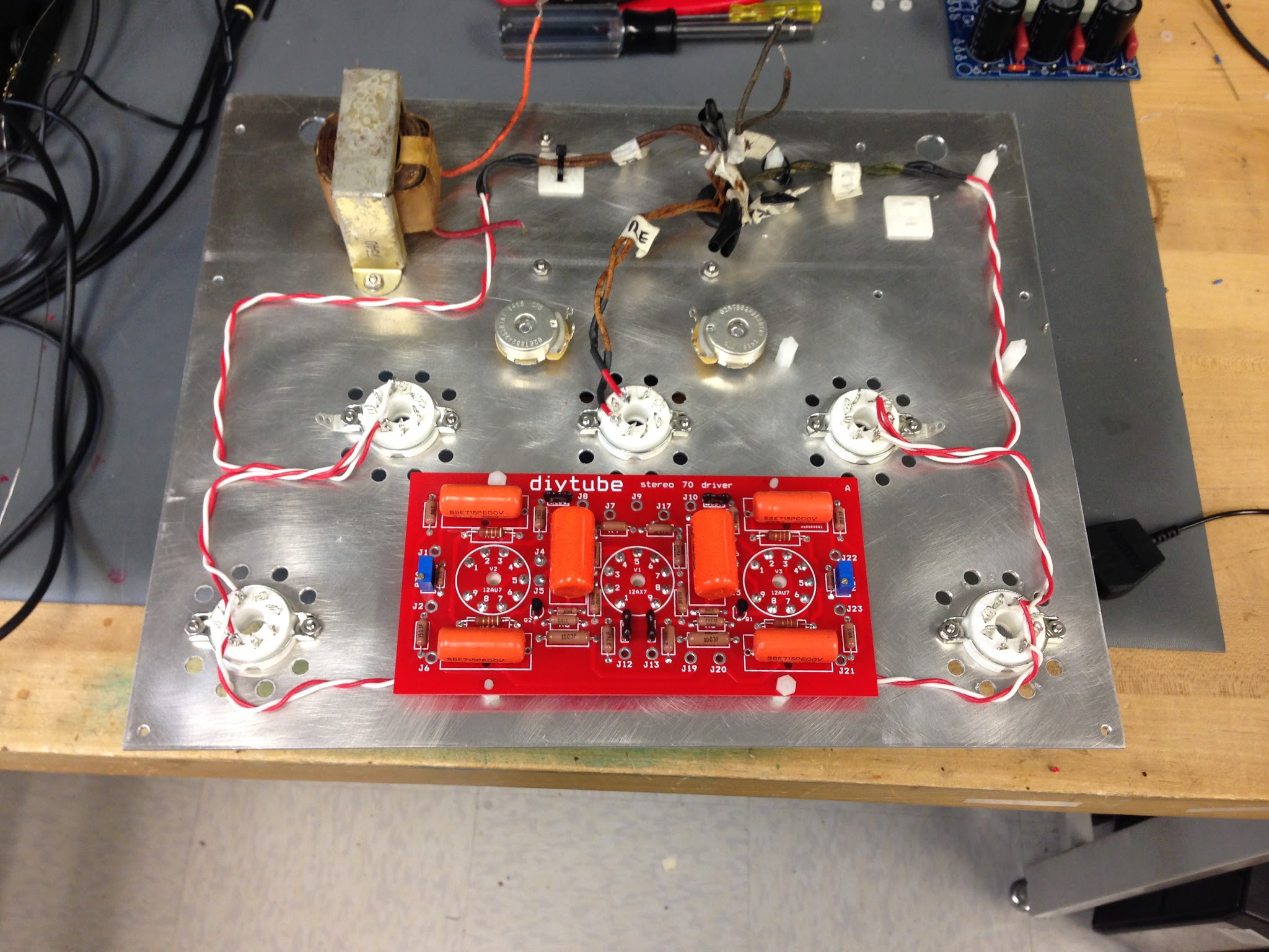

I continued wiring:


(The big power choke in the photos above came out of an amp I pulled out of a garbage dump when I was 15. Pretty proud of that. I used an LCR meter and a hi-pot tester to characterize it.)
Testing
(Warning: the next 3 paragraphs are pretty technical—if you're unfamiliar with circuits you may want to skip.)
I wired and then powered up the amp in stages using high-watt resistors as dummy loads. I started with the power supply, added the output tubes, and then added the driver board. In the course of this process I changed the operating point of the output tubes. I had originally used the same values used in the AA-100, but I decided this was too close to the max power dissipation. With assistance from the good folks at Audiokarma I redrew the loadline to operate the plates at 430V and the screens at 325V with my 7.7K transformers. I sacrificed some output power doing this but I think it was worth it for sonic improvement and longevity. My loadline drawing is in the attachments.
The new operating point required adding a resistor in the power supply immediately after the rectifier tube in order to drop the voltage to 430 (big thanks to the good folks at dcaudiodiy.com who pointed out that I could use a lower-value resistor by placing it before—instead of after—the first capacitor bank). I originally tried to drop the plate voltage by adding zener diodes in series with the secondary ground on the power transformer. I neglected that this would change my bias voltage and I ended up smoking a capacitor. It's not a real build if you don't smoke something, right?
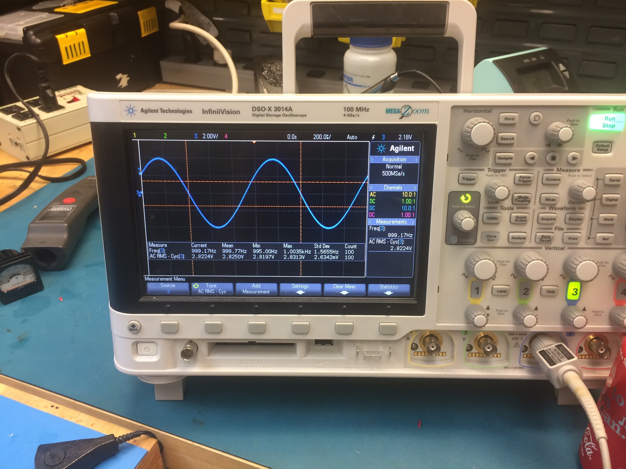
With everything wired it was time to start testing. Using 8 ohm dummy load resistors I measured that the maximum output per channel before clipping was 20W (thus, the name "ST-40"). I measured frequency response from 20 to 20K Hz and found it was within a dB across the band. I checked for hum with my scope but couldn't find any. I put a square wave on the input and tweaked the value of an RC filter in the driver stage to reduce ringing. I then tested a variety of different capacitor loads while varying the input frequency to check for instability. Unfortunately I found that when unloaded, the amp would go into oscillation. I asked dcaudiodiy.com for some suggestions and one of the guys there graciously invited me over to have a look at the problem. We ended up reducing the gain of the first stage and increasing the shunt capacitance of the feedback network. The amp was cured.
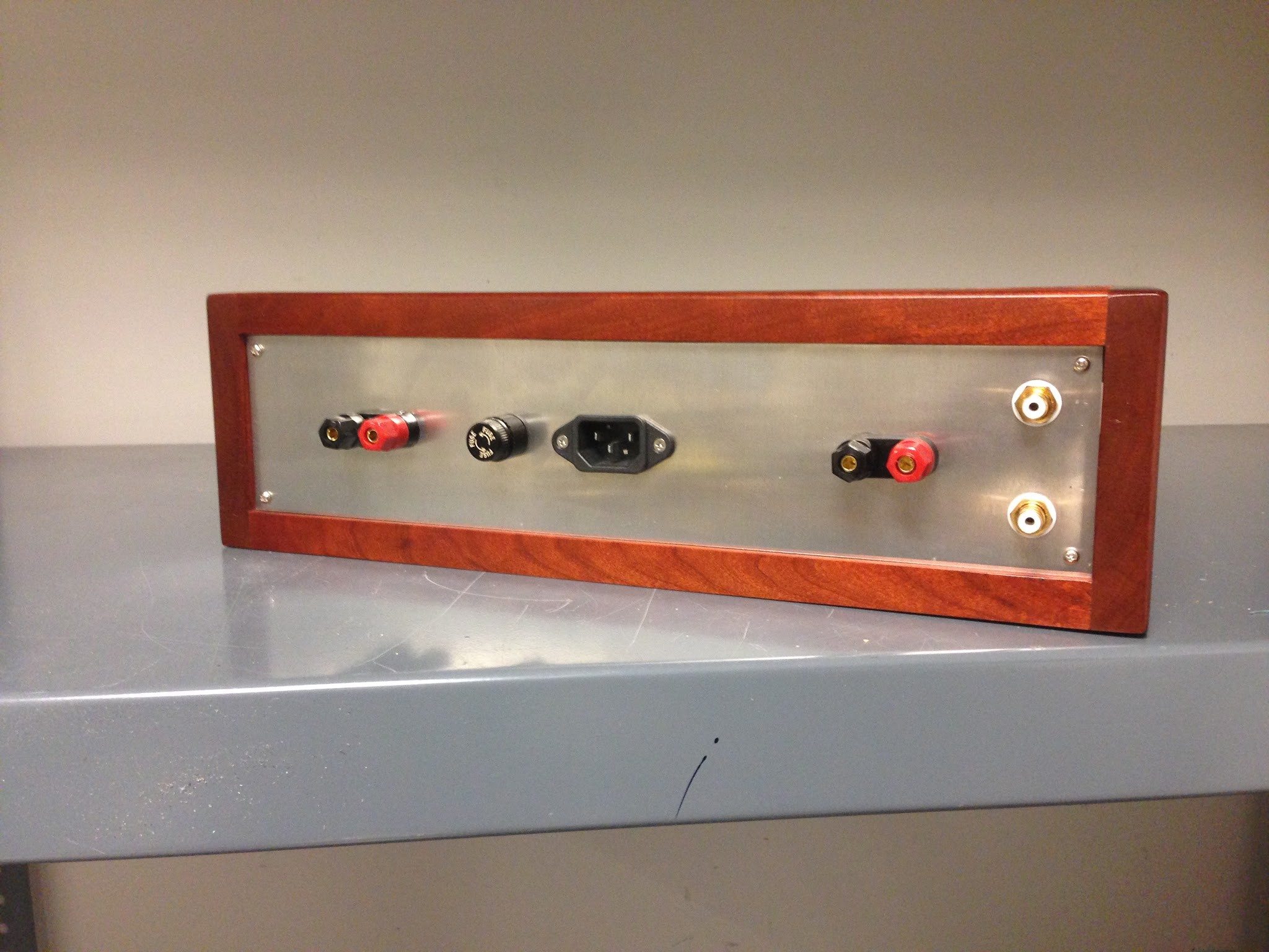
At this point I completely assembled the amp. I added a selector switch on the back so that the meter can measure the bias points on all 4 output tubes as well as the 300V power rail.
Completion
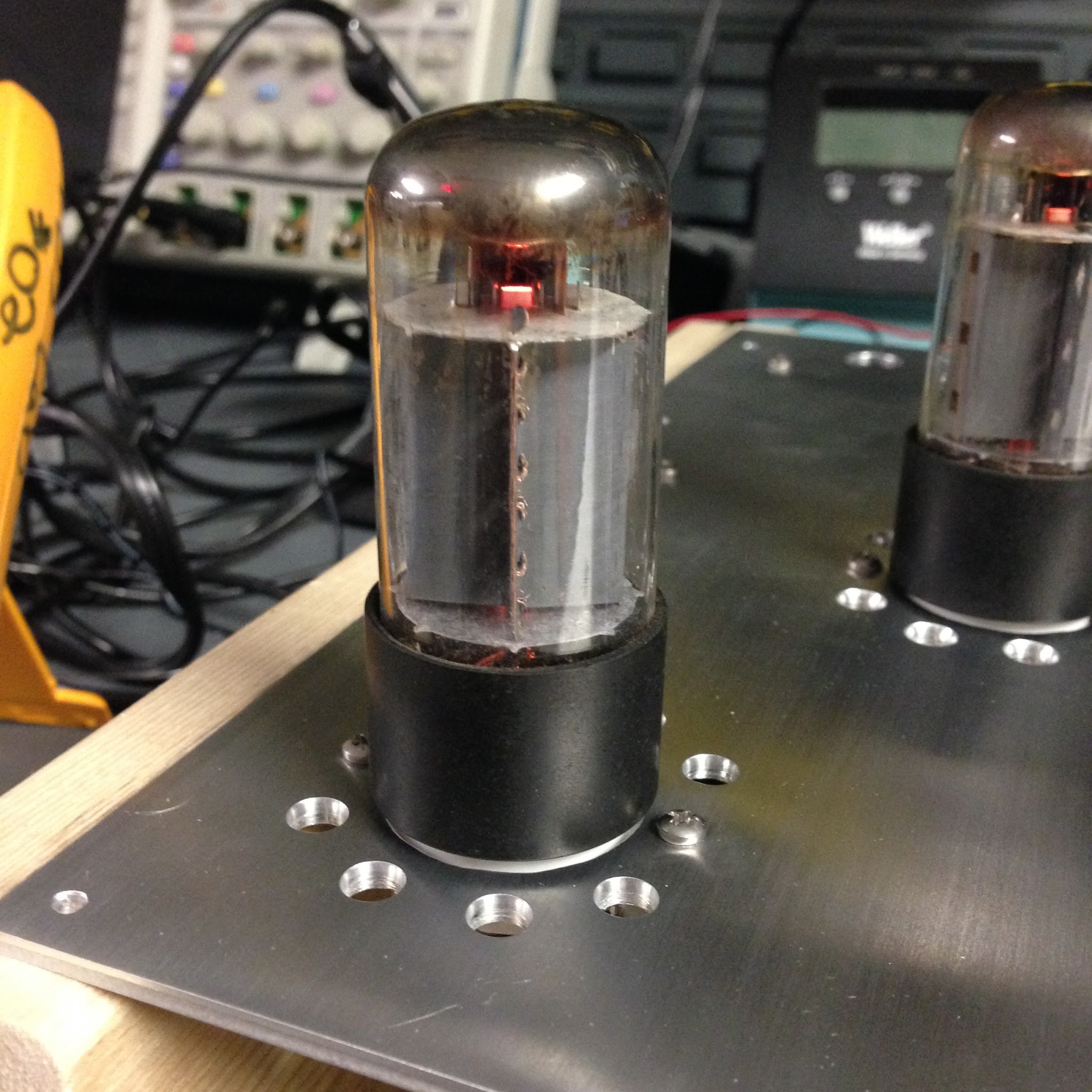
Finally, nearly 2 years after I started the project, I fired it up with my speakers. It sounded just awesome.
Resources
Valve Amplifiers, Morgan Jones
Building Valve Amplifiers, Morgan Jones
Audiokarma.org
dcaudiodiy.com