 Beast Devices
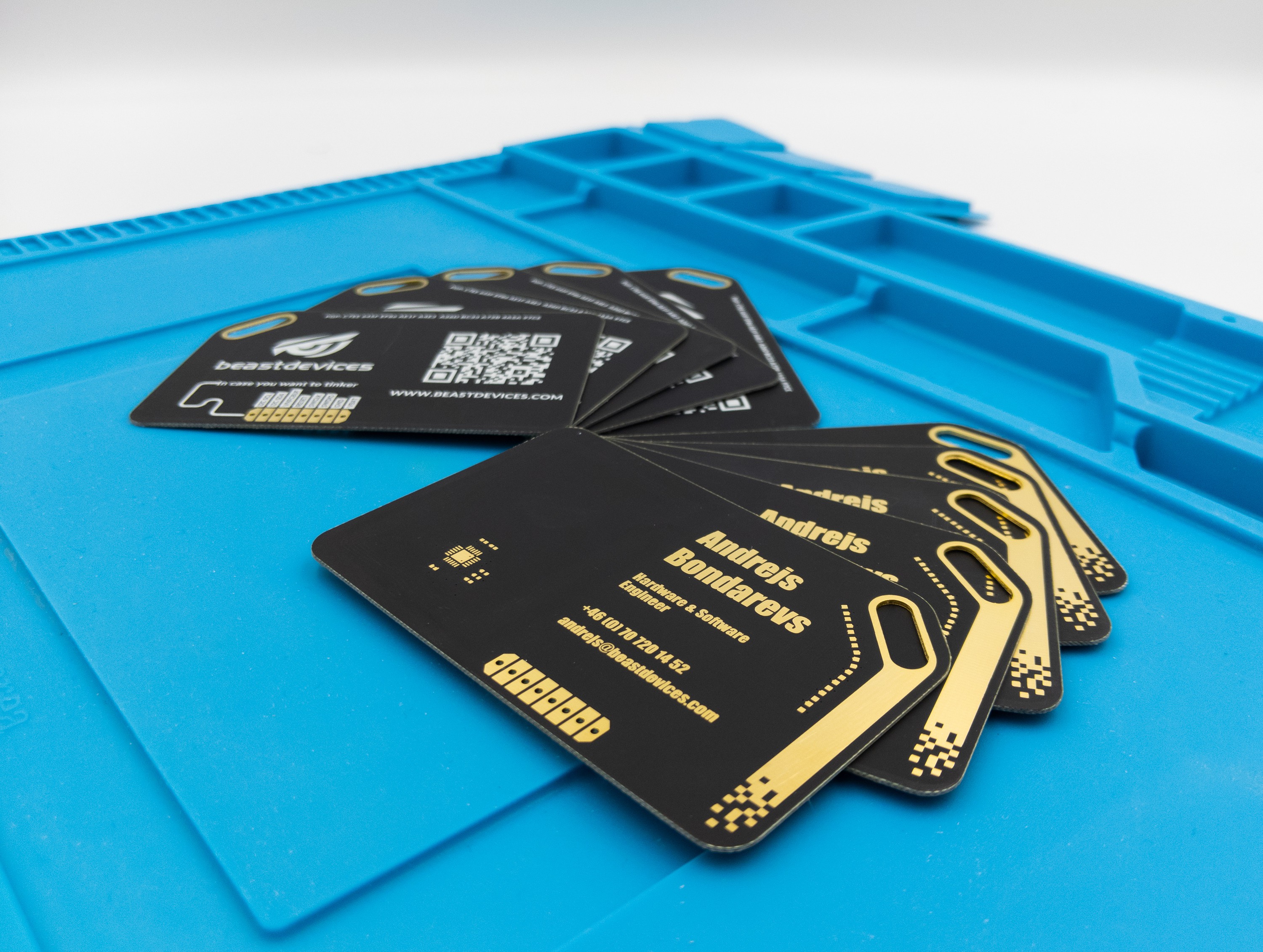
It uses NXP LPC8N04, and features nine 0.4 mm slim orange LEDs for the light show and feedback. The MCU itself consumes only 900uA at 8MHz and 200uA at 1MHz. Given that NFC readers provide power continuously, there are many application that could be implemented on the business card. I haven't came up with anything fancy yet, except for hooking up I2C sensors, and using LEDs and time interval that card is held against the NFC reader to change the mode of operation. If you have any ideas, leave the comment below!
0%
0%
Beast NFC Business Card
Cortex M0+ NFC badge and business card
Become a Hackaday.io member
Already have an account? Log in.
Just one more thing
To make the experience fit your profile, pick a username and tell us what interests you.
Pick an awesome username
hackaday.io/
Your profile's URL: hackaday.io/username. Max 25 alphanumeric characters.
Pick a few interests
Projects that share your interests
People that share your interests


 Pete Prodoehl
 Christopher Sainsaulieu
 Sri
Sri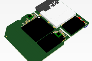
 Antti Lukats
Hi! Great project! I was looking for something very similar to experiment with having storage on a card too. The LPC8N04 looks like a powerful device to play with.
Are you able to share the CAD files for the PCB design? I’m most interested to see how you designed the antenna. A more generic version of the PCB without your artwork would be great! (Especially if it is on your GitHub with the software sources!)
Thanks!