Close
0%
0%

Reboot-o-matic

Automatic power-cycling made safer

Similar projects worth following
Starting from
$12.50
nsayer has 2293 orders / 162reviews
Ships from United States of America
We have a vacation home. It has an Internet connection and there are some home automation devices that we like to monitor remotely. Alas, the router is not 100% reliable, so there are occasions where the Internet gets stuck. This doesn't happen often (if it did, we'd buy a different router), but when it happens when we're not there, it's a pretty major inconvenience. If we were there, we'd just power cycle the router and be done.

Since there's a Raspberry Pi there, we could use ping scripts to make a watchdog for the router, but we don't want to make things worse by doing it poorly.

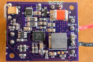
Since most SoHo networking gear these days are powered by DC wall warts, we don't have to design a switch for AC. It's enough to just put a P MOSFET in the positive DC rail (that MOSFET needs to be kinda beefy is all). The MOSFET has a pull-down (we want the power to default to ON, after all) on the gate and a second P MOSFET is set up to pull the first MOSFET's gate up to turn the power off. This second MOSFET is necessary because the first MOSFET's gate must be pulled up to the input voltage rail, and the thing doing the pulling is running at a lower voltage than that. The second P MOSFET's gate is pulled up rather than down, so that it defaults to off (remember, turning that MOSFET on means turning the main power off).

The gate of the 2nd P MOSFET is pulled-up to the input rail and connected up to a third MOSFET, this time an N channel one whose gate is pulled down and connected to a microcontroller pin.

One issue with powering the circuit at higher DC voltages is that we must not exceed the maximum gate voltage of the two P MOSFETs. The usual mechanism for doing this is to add a zener diode between the gate and positive rail. For the second P MOSFET, whose gate is pulled to ground by the N MOSFET, we also need to add a current limiting resistor to protect the zener diode. However, it is possible to do without the zener diodes if you insure that the maximum Vgs of the two P MOSFETs exceeds the working voltage for the equipment you're controlling. Since most SOHO routers have a 12 volt supply, that's not hard. I chose DMP3099 transistors because they have a 20 volt Vgs, 30 volt Vds and maximum Id of over 3 amps.

This rather Rube Goldberg transistor arrangement allows us to use a low powered microcontroller to turn the output power off briefly, but with everything defaulting to the "on" state (in case something goes wrong). Imagine, for example, if the microcontroller failed to start. If we required an asserted output to turn the power on, then this failure would result in the power being off permanently. The microcontroller failing by shorting an output to Vcc is much, much less likely.

The microcontroller is a simple ATTiny9. In addition to the output pin, there is an input pin that comes from the outside. There's a protection diode on the input that prevents any voltage fed into that pin from arriving at the controller. The pin is defined as an open-drain input. You short that pin to ground to request a power-cycle.

You wouldn't necessarily think that a controller would be required for this, except that we want the controller to have some rules to act as a fail-safe for the system. It has software de-bouncing in place, so that the input has to go low and stay low for a full second before the power is cycled. The power is cycled for 10 seconds, and then the input has to go high and stay high for an hour before any low transition is allowed.

The microcontroller is powered from an LDO fed by the input power rail. It's consumption is so low (less than 1 mA) that we can use a SOT23-5 unit and still be unconcerned about it's power dissipation over it's entire input voltage range.

Adobe Portable Document Format - 25.33 kB - 05/03/2021 at 14:45

Preview
Download

sch - 232.73 kB - 05/03/2021 at 14:44

Download

brd - 56.24 kB - 05/03/2021 at 14:44

Download

Adobe Portable Document Format - 32.14 kB - 11/15/2019 at 05:45

Preview
Download

sch - 387.98 kB - 11/15/2019 at 05:45

Download

View all 6 files

  • Another mechanism for this

    Nick Sayer05/03/2021 at 15:39 0 comments

    It occurs to me that the Pi-with-watchdog-script isn't the only way you could make this work. You could also use some type of cellular modem device capable of receiving text messages. If the router was stuck, you could send a text message to the watchdog that would cause it to engage the open drain output for 2 seconds and reply with an acknowledgement.

    I might see if I can come up with a way to connect an Adafruit FONA 3G to the Pi.

  • Better transistors

    Nick Sayer07/18/2020 at 23:56 0 comments

    One of the reasons I added the two zener diodes to the design was that the P-MOSFETs I had on hand had only an 8 volt maximum Vgs and I needed to run the system at 12 volts.

    You can get better transistors, though. The DMP3099L-7‎ is an excellent candidate. It has a maximum Vgs of 20 volts, a maximum Vds of 30 volts and a maximum drain current of almost 3 amps at 70ºC. If you use that part, then you can leave out D2 and D3 and use 0Ω for R2 (though it does no harm to leave it at 10kΩ).

    EDIT: In addition to better transistors, I've also discovered a SOT23-5 5 volt LDO that has an ultra wide input range. It was a little extravagant to use the D2PAK packaged 7805 for this job, given that the ATTiny9 draws maybe 1 mA total. Even if it were 1 and you were running the whole thing on the maximum input voltage of 20 volts, that's a dissipation of less than 15 mW. That's 3ºC above ambient (given the 235 ºC/W to-ambient dissipation rating for the chip), which is not a big deal (and that's the worst case).

  • Attiny9

    Nick Sayer06/07/2020 at 03:43 0 comments

    I've taken a shine of late to the ATTiny9. It's a microcontroller in a SOT23-6. Like, the size of a grain of Arborio rice. You only get 4 I/O pins (and really only 3 unless you repurpose !RESET), but projects like this only need 2.

    So I don't have a need to do so, but I think I will spin a rev of this project to use the tiny9 just to see if it can be done. I hacked up the firmware with "if defined" to differentiate between the tiny85 and tiny9 versions of the code. I haven't checked any of that in yet because it's not tested, but I will do so once I confirm that it all works.

    The hardest part is going to be TPI based programming. The ATMelICE can do TPI, but avrdude doesn't support TPI on it (just ISP and PDI). So I am probably going to start with ATPROGRAM on a Windows vm (ugh). If it's possible to hack avrdude to add TPI support for the ICE, I'll do so.

    EDIT: The programming problem has been put completely to bed

  • The root cause

    Nick Sayer12/12/2019 at 21:13 0 comments

    This isn't really related to this project, but we did figure out the root cause of the router instability. It's the fault of our Samsung smart TV. It's apparently using the hostname "localhost" in its DHCP requests. That causes a bunch of logging and other complaints from the DHCP server built in to the router's dnsmasq instance. What then causes that to result in the interfaces wedging is unclear, but giving the TV a static address made the problem go away.

    EDIT: Well, it turns that the jury has not yet entirely returned a verdict yet...

  • First shot fired in anger

    Nick Sayer11/29/2019 at 18:53 0 comments

    We're up at the vacation villa this week and I installed the watchdog and set up the Pi that's in residence to take care of business. Well, last night in the middle of the night the router wedged itself and the Pi and box did their job flawlessly and brought everything back.

    I've decided to run the script every 2 hours instead of 4 (so the cron spec is 0 */2 * * * $HOME/watchdog.py), and I've reduced the testing timeout to 30 minutes from 60 (a firmware update should take no longer than 15 minutes including time to get the system back up).

    Of course, it would be better if this sort of thing just simply didn't happen and the router was reliable, but I don't think any router is going to be reliable enough that I'd not want to keep this system in place, frankly.

  • New firmware rules

    Nick Sayer11/15/2019 at 17:41 0 comments

    I've changed the firmware so that the holdoff interval is no longer restarted when there's an input pulse. Before, if you pulsed every 59 minutes, then the reset would never happen. The more I thought about that, the less I liked it.

    Now if you pulse during the holdoff it won't do anything, but if did it every 59 minutes then every other one would still work.

    In addition, just tying the line permanently to ground will reset the system once and never again. The input has to be successfully debounced to "off" before any attempt to turn it "on" will be recognized. And, again, the debounce interval is one second. The line has to stay either "on" or "off" for a full second before any change is recognized. And for "on," that state change is recognized exactly once and then it has to transition successfully to "off" before it can be recognized as "on" again (note that this description is of the input to the circuit - where "on" is shorted-to-ground and off is open).

    That's about as robust a system as I can envision that doesn't involve sending commands or stuff like that.

  • Oops

    Nick Sayer11/15/2019 at 05:44 0 comments

    It's occurred to me that if you power the circuit at 12 volts, Vgs for the P MOSFETs will be the full 12 volts when they're turned on. This is problematic as the MOSFETs I've designed with have an absolute maximum Vgs of ±8 volts. The fix is simple - each of the P MOSFETs needs a zener diode to limit Vgs. For the output MOSFET it's as simple as placing a zener diode from the gate to the positive rail. There's no need for a pull-up because the gate is normally pulled-down and the switching is across the zener. For the switching P MOSFET, we need to add the same zener to the positive rail, but also must add a pull-up across the zener because the switch pulls the gate momentarily down. There also needs to be a current limiting resistor added in series with the switch to limit the zener current. When the supply voltage is less than the zener voltage, then you can imagine that they're just not installed. When the supply voltage is higher, then you can sort of assume that the voltage on the anode is lower than the cathode by the zener voltage amount.

  • Build report

    Nick Sayer10/31/2019 at 21:13 0 comments

    It works!

    I checked in the watchdog script into the firmware repository. It now uses syslog rather than standard out/err for some rudimentary logging. My recommendation is that you run this from cron every 4-6 hours. You can't really run it more than hourly, since there's a one hour hold-off in the firmware that is reset if you try to do the reset before the hour is elapsed (so if you pulse the action pin every 59 minutes, it will never actually work after the first time).

    The reason you don't want to run it more frequently is that if everything goes terribly wrong and it's doing something crazy, you want to have a chance to get in and stop it. The one-hour firmware hold-off should give you a chance even if everything else goes sour.

    The only thing left would be to make a 3D printed case for it, but I don't know if I care that much. We'll see.

  • A better cut at the watchdog script

    Nick Sayer10/24/2019 at 15:57 0 comments

    I thought of a couple of issues with the first script.

    If the router is performing a firmware update, the internet may be unreachable for 10 minutes or so, and it would be a disaster to power-cycle the router then. So the script should keep trying for a solid hour to reach an external host before giving up.

    I've also expanded the list of hosts. These are all public DNS servers. Again, using them as ping targets is probably not what their owners had in mind, but the script as written is being very gentle (and answering a ping is a lot less work than answering a DNS query). As long as you only run this no more than once every 6 hours or so (and as long as everybody and their brother doesn't run it), I would think it would be acceptable.

    #!/usr/bin/python
    
    import RPi.GPIO as GPIO
    import sys
    import time
    import subprocess
    import os
    import random
    
    hosts = ["1.1.1.1", "1.0.0.1", "8.8.8.8", "8.8.4.4", "8.26.56.26", "8.20.247.20", "9.9.9.9", "149.112.112.112", "64.6.64.6", "64.6.65.6"]
    random.shuffle(hosts)
    
    FNULL = open(os.devnull)
    
    start = time.time()
    while True:
        for host in hosts:
            res = subprocess.call(["ping", "-c", "3", "-W", "5", host], stdout=FNULL, stderr=FNULL)
            if (res == 0):
                print(host + " is up.")
                sys.exit(0) # it worked. Bail
            else:
                print(host + " is down.")
        if time.time() - start > 60*60:
            break
        time.sleep(5 * 60) # wait 5 minutes
    
    print "All hosts unreachable for 60 minutes - resetting router"
    
    # physical pin 7
    reset_pin = 4
    
    # Perform the reset operation
    GPIO.setmode(GPIO.BCM)
    GPIO.setup(pin, GPIO.OUT, initial=GPIO.LOW)
    time.sleep(2)
    GPIO.cleanup()
    
    sys.exit(1)

  • Depletion mode MOSFETs

    Nick Sayer10/23/2019 at 23:29 4 comments

    Just before someone brings it up... the two P MOSFETs could be replaced by a depletion mode P MOSFET. Depletion mode MOSFETs work just like the more ordinary enhancement mode devices, with the sense of the gate being backwards. Where increasing the amplitude of the gate-source voltage would turn an enhancement mode MOSFET on, doing so with a depletion mode device turns it off instead.

    Unfortunately, depletion mode devices are out of the ordinary, so the prospects of using one - particularly one that can pass 2 apps continuous - are poor. 

View all 12 project logs

  • 1
    Requirements

    The device you intend to control must run on DC power, with a voltage at least above the LDO's drop-out voltage. In principle this probably means no less than 6 volts. The maximum voltage is limited by the absolute maximum input voltage of the LDO and its power dissipation (the 5v draw should be 1 mA or less, which implies that there should be almost no limit based on dissipation) and the absolute maximum Vds of the main power MOSFET. The maximum current drawn by the target device is limited solely by the absolute maximum Ids of the main power MOSFET (the gate voltage should be sufficient to saturate it or keep it fully off, so there should be no Vds dissipation concerns). In practice, the expectation is that the vast majority of equipment that you'd use would be powered by either 5, 6, 9 or 12 volts DC. 5 volts is too low for the LDO, but it would likely still work, as the controller itself can work well below 3 volts (it's default fuse configuration sets the system clock to 1 MHz, where it will operate down to 1.8V), and its operating voltage is not terribly critical (as long as its "high" output is enough for the Vgs threshold of the N MOSFET).

    As designed, it requires center-positive 2.11m barrel connectors for the power, though with design changes on the board this can be altered to fit your needs.

  • 2
    Hookup and usage

    If you're using a Raspberry Pi as your watchdog host, then connect the control header up to pins 6 (GND) and 7 (GPIO4). Run the watchdog script every 4-6 hours or so from cron. The script must be run as a user who has GPIO permission.

    Plug the router's power plug into the jack on the board. The power light on the board should light up. Plug the output plug from the board into the router. The router should power up normally. You can test the hardware by copying the watchdog script and deleting the stuff in the middle that actually checks the IP addresses. Setting GPIO4 low for 2 seconds should cause the router to power off for 10 seconds and then power back up. Repeating that low pulse in less than an hour should result in nothing happening.

View all instructions

Enjoy this project?

Share

Discussions

Andrej wrote 11/03/2019 at 22:05 point

what about OpenWrt?

  Are you sure? yes | no

Nick Sayer wrote 11/03/2019 at 22:06 point

What about it?

  Are you sure? yes | no

Andrej wrote 11/04/2019 at 08:59 point

like using openwrt so you don't have to power cycle your router

  Are you sure? yes | no

Nick Sayer wrote 11/04/2019 at 14:37 point

I have zero confidence that OpenWRT would be more reliable than the firmware I have. 

It’s not that this happens very often. It’s that the couple of times it has happened have been a major inconvenience. 

  Are you sure? yes | no

r.e.wolff wrote 11/02/2019 at 18:47 point

The mainloop in your script would read easier if you put the 

  start-time() < 60*60

as the condition in the while statement. 

Another code-style comment: Consider putting the "make output low" in a separate statement. It saves a line the way you're doing it now, but if you separate it out you get a real "action" statement that actually does something. (now it is an initialization statement that DOES something!)

I would personally run it much more frequently than you do. Maybe like every hour. And then reboot if you don't see internet after 15 minutes. Then, say the case that you can ssh in, but the script thinks things are broken, then if you start the script at xx:45 you have from 5 past the whole hours to 55 past the hour as a guaranteed continuous ontime to "fix things" or "get in and disable the script". 

All this "style" and  opinion, if you want to keep it the way it is, fine. 

  Are you sure? yes | no

Nick Sayer wrote 11/02/2019 at 19:34 point

The issue with the do-while phrasing is that we want to do the 5 minute wait only if the hour has not elapsed. We want to jump to power-cycling the router if the last test has failed and not wait 5 minutes for no reason.

If you want to run the script at close to an hour frequency, then you should reduce the dead time in the firmware. The clock in the controller is not terribly accurate, and the clock division isn't either, so you ought to give that hour a good +/- 10% slop. And the way the firmware works, if you try to jump the gun after rebooting it, then it restarts the hour hold-off. So if you do it every 59 minutes, then it'll work once and never again.

For our router, a firmware update takes something like 10 minutes, and power-cycling the router during that time would likely brick it, so that's why it has to fail for a whole hour before it gets power-cycled.

All of this is easily tunable by anyone who wants to implement it.

  Are you sure? yes | no

Dan Maloney wrote 10/23/2019 at 15:38 point

So will the Pi be running scripts that are looking for maybe ability to ping a server outside the LAN to determine if it needs to bounce the router?

  Are you sure? yes | no

Nick Sayer wrote 10/23/2019 at 16:23 point

Exactly. Though that's sort of out-of-scope for this particular project - you ostensibly could use this for any sort of watchdog, not necessarily network hardware.

EDIT: Well, I said out-of-scope, but I've checked in a network watchdog script into the repository, so I guess it, in fact, is in scope. But the hardware doesn't care, of course.

  Are you sure? yes | no

Similar Projects

Does this project spark your interest?

Become a member to follow this project and never miss any updates