Here are some more notes concerning the sweep generator circuit that provides the modulation to the VCO, and some alternative circuits you may explore.
On my previous post on the sweep generator, Leo Liu pointed out to me that the XR2209, Exar's replacement for the XR2206 waveform generator, is still in production. This chip is potentially useful if you want to follow the MIT design as closely as possible for your basic FMCW radar project. The XR2209 is only an 8-pin package as opposed to 16 pins, but the internal architecture is pretty similar, just simplified a bit to reduce the pin count - read the datasheets and you should be able to port Charvat's XR2206 schematic across to the right pins on the XR2209 fairly easily, and you're also saving a bit of board space with the 8-pin chip.
Some of Liu's undergrad EE students at UC Davis have also recently been building some basic FMCW projects somewhat derived from or inspired by the MIT/Lincoln Lab work - and looking through their material I noticed they've recently been featured in a Hackaday post which you can see here. (Although to be slightly pedantic, personally I would have considered Tony Long's "RadarDuino" as the first radar system on an Arduino shield.)
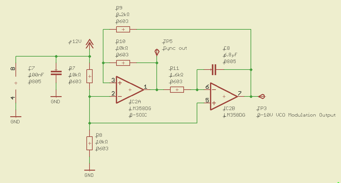
The schematic below shows another alternative circuit you may consider for a basic triangular sweep - just your classic Schmitt trigger integrator circuit to generate a triangle wave. This is a very simple low-cost circuit, using only about 50 cents worth of simple jellybean components you can get anywhere, which you've probably already got on hand at your home lab, school or hackerspace.
Another reason I like this approach is that I do sometimes like to encourage people to remember how to design and use real electronics to solve a problem, rather than the "MICROCONTROLLER ALL THE THINGS!" approach. Microcontrollers have their place, and can be really valuable in the right context - but for a lot of simple jobs, the "old" ways with fixed-function electronics can be simpler, easier and cheaper if you don't need the power and flexibility of a microcontroller. But sometimes the microcontroller kids these days don't grasp that - through no fault of their own, though, and perhaps more exposure to electronics outside of the microcontroller domain (and including the stuff that surrounds the microcontroller, in any microcontroller system) would help with that. Microcontrollers can be good, but just because you can use them for everything, doesn't mean you need to use them for everything or that you always should. (But if you're really itching to write some code and pump some SPI bytes, scroll down a bit.)
When using a common, cheap opamp such as an LM358, one point to be aware of is that the output can't swing all the way up to the positive supply rail - it will be limited to a couple of volts less. One way to solve this is with a rail-to-rail opamp, but usually it's easy to avoid the problem without adding the cost of a rail-to-rail device - just power the opamp from a supply rail a couple of volts higher than the desired maximum output. Here I'm using a 12V supply. You don't need a bipolar power supply either - a single-sided supply works just fine.
You can probably add some tweaks to this circuit if you want - add a trimmer pot to this circuit for frequency adjustment, change the output amplitude if you're using an 0-5V VCO, etc. I'll leave that as a homework exercise for the reader. You can also take the square-wave output at the output of the first opamp, and use this to sync your PC software (or whatever data acquisition platform you're using) with the start of the sweep. Note that the start of the positive ramp (the minimum of the triangle wave) corresponds to the falling edge of the square wave, and also note that this is a 0-10V signal - you'll want to attenuate that before plugging it into a PC sound card.
Another good option to consider is the use of a microcontroller (or PC)-controlled DAC which generates the modulation waveform. In this example I used a Microchip MCP4921 since that's what I had on hand, but there are many other candidates you could use. One of Microchip's 10-bit SPI ADCs might be a good low-cost choice - I really don't think you need 12 bits of resolution, and 10 should be more than sufficient for good performance.
An advantage of a microcontroller-based approach is that it gives you a great deal of flexibility to experiment with different modulation waveforms, different frequencies, different options you can easily select during operation etc - all under software control. The following is the basic circuit I used, just for demonstration purposes.
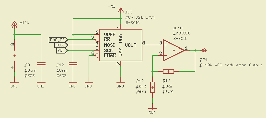
If you wanted to be really fussy about the integrity and precision of the DAC output, a dedicated voltage reference may be used - but I didn't bother in this case, I just tied it to the 5V supply. Control of when the DAC latches isn't important here either, just tie the latch input to ground. Another jellybean LM358 (with 12V supply) was used to amplify the output to 0-10V, although if you're using an 0-5V VCO then just taking the DAC output (assuming a 5V reference) straight into the VCO should work fine. If you want to limit the sweep bandwidth to a fraction of the VCO's capability you can just do it in the software that controls the DAC.
And the results look something like this:
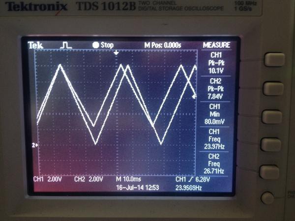
The amplified DAC output, on channel 1, nicely spans the full available VCO bandwith, across 0-10V, as well has having programmable waveform shape and frequency (subject to realistic limits - how fast can your microcontroller and your code pump out new updates into the DAC?), and it's quite a clean triangle wave. A nice result.
The smaller-amplitude signal on channel 2, which goes from an amplitude of about 2-10V, is the output from the very simple Schmitt trigger/integrator circuit shown above, using only a single LM358 and a couple of caps and resistors. This is also a pretty clean, undistorted triangular sweep - and this very low-cost circuit is probably sufficient for you to get a basic FMCW radar setup that is functional. Even though this circuit in its current form (something very crude I quickly threw together) doesn't access the full available bandwidth of the 0-10V VCO, you actually don't really need all that bandwidth.
If you want to use a microcontroller there are actually several other options you could try for digital-to-analog conversion without the performance of a dedicated serial DAC chip, saving a couple of dollars on your BOM. You could try an R-2R ladder DAC if you've got lots of microcontroller pins to spare - an old classic! Or you could try generating a waveform using high-speed PWM to generate a pulse train with varying duty cycle, and then filtering it. This is described in Atmel's AVR131 application note, for example. This approach means you're using only a single microcontroller pin and only a couple of jellybean components to make a simple RC low-pass filter plus an opamp as a voltage follower maybe (or for gain if you need 0-10V out), so the cost in terms of both microcontroller pin count and other components is very low, if your design already incorporates a microcontroller. I haven't tried this approach yet but I'll leave it as an exercise for the reader.
Discussions
Become a Hackaday.io Member
Create an account to leave a comment. Already have an account? Log In.