3D Files (STL and customizable STEP files): https://www.printables.com/model/344052-worlds-simplest-neuralizer-men-in-black-memory-era
In the video above you can follow our build process and a detailed explanation of the circuitry and the design choices that were made.
The simplest possible circuit is really simple. Using a 3-state switch (shown in the video), where the middle state is "do nothing" and the two other states represents charging and discharging of the capacitor - this is what the schematic looks like:
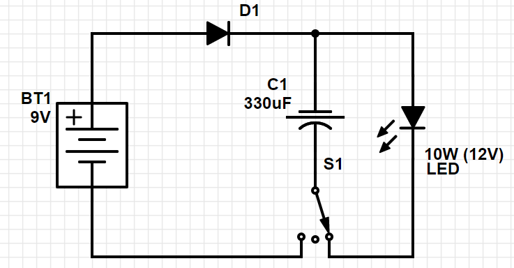
There is no current limiting resistor to protect the LED because it's specified to run at 12 Volts, and the battery will only provide 9 Volts. In the design we used ourselves we actually did place a small 3 ohm resistor in series with the LED, but as shown above, that is not strictly necessary. So if you want to make the soldering-job as easy as possible. Go with the design above.
ALTERNATIVE CIRCUIT DESIGNS:
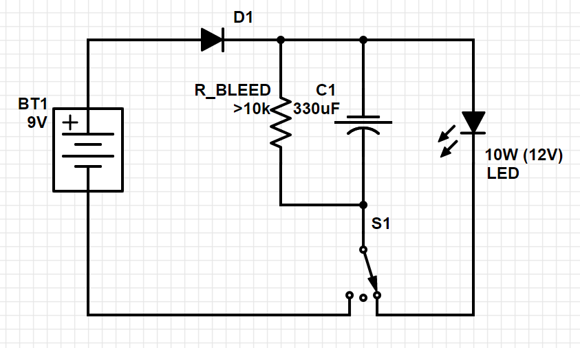
In our design we also included a discharge resistor that will make sure that the capacitor doesn't stay charged over long periods of time by evening out the potential stored over the capacitor. The value of this resistor obviously needs to be quite high, so it doesn't allow the voltage to even out immediately, but unfortunately I didn't write down the exact value we used, so the 10k in the following schematic is just a guess.
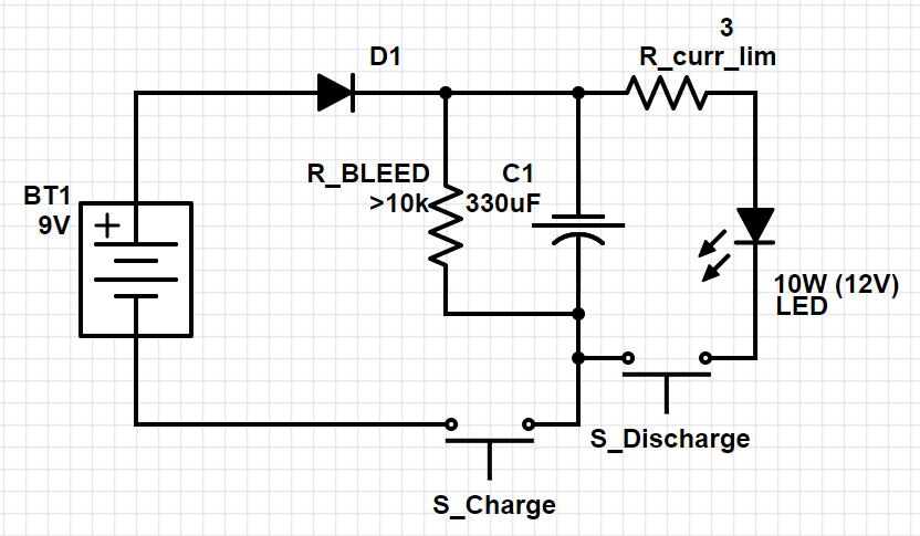
The next alternative circuit is the one that we actually used on the bread board in the video at the top. Here you can see that the 3 ohm current limiting resistor is included, as well as a two button system that replaces the tri-state switch. This allows for a constant current path through the LED, bypassing the charging and discharging of the capacitor - by holding down both buttons at once. This gives the possibility to use the Neuralizer as a flashlight.
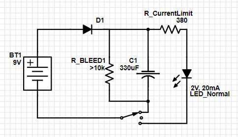
The switches can also be replaced with simple two-state toggle-switches, but then the R_bleed resistor must be removed because the equivalent to one of the swithes S1 and S2 in the circuit above will always be "pushed" (eg. the toggle switch will always connect one of the two ways). That would mean that R_Bleed will leave a constant current path between the anode and cathode of the battery - draining it.
Next up comes a variant that uses a "normal" LED rated at 2V and ish 20mA. Here, the current limiting resistor must be taken into account, otherwise, the circuit stays the same.
There are more ways to do this circuit, depending on what parts you have available. It is also possible to mix and match between the alternatives posted above.
 Applied Procrastination


 Keith
Keith
 Simon Merrett
 Scott Clandinin
Slightly disappointed, was hoping for "almost might kinda work in theory on a handful of subjects" type build. i.e. attempt to trigger brainwave patterns like those achieved in hypnosis to make the subject suggestible. Though it would probably be as likely to trigger seizures as "work".