There are only a handful of parts to build this - a few resistors, decoupling caps, headers, PIC, and of course, the LCD. There are two 6-pin headers. The male is for programming the PIC directly with a PICKit 3. The female is just what I had on hand for a quick micro-USB adapter cable to connect the MPPT Charger project. The POT is for contrast adjustment.
The electrolytic cap provides local bulk storage to reduce ripple from the PIC's PWM that drives the LCD backlight. It can draw up to ~ 15mA. Both caps should be located as close as possible to the PIC's Vdd & Vss pins. The unit derives 5V DC power from either the ICSP or RS232 connectors and draws a maximum of 17mA.
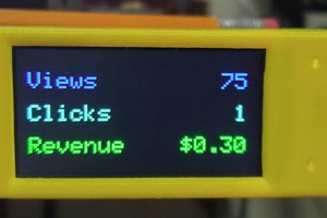
Operation is very simple. Once booted the MCU enters a run loop that queries the charger and waits for a response. The charger sends a binary packet of data, the MCU validates, and then displays. If it encounters problems (no response, data corruption, etc.) it displays an error message and tries again at the next update interval.
To conserve power, the backlight is on only when the charger indicates that it is running. I added a push-button to momentarily activate the display when out so I could see what's going on when the charger is idle. Since the backlight is controlled by PWM you could add a dimming function to adjust to ambient light levels (to do so you'd need to share one of the ICSP pins).
That's it! You could easily adapt this format to other query / display needs. It also wouldn't be too difficult to modify the firmware to function as a serial / parallel pass-thru to control the display directly from the remote system.
The MPLAB project zip has everything needed for the firmware except the include file dspstatus.h which is shared with the charger project. You can get it from that project's MPLAB zip file.
 yo2ldk Alexandru