 256byteram
The Oscillator

The oscillator is a regular Phantastron oscillator (6AU6) configured to generate a sawtooth waveform. The output on the anode is wired directly to a cathode follower (right 6BQ7A) to buffer it, with the integrating capacitor wired from the cathode back to the pentode's grid. The summing node on the pentode is where current is applied, which generates a frequency proportional to the amount of current flowing into the node. The voltage does move around a lot because there isn't a lot of gain in a single pentode.
The voltage to current conversion is done by the first triode. I found the 6BQ7A dual triode to be the best fit but a 12AT7 will also work. To get a constant current out of the triode you need to have a constant voltage across the cathode and grid. Because the cathode is connected directly to the summing node, which moves around, the control voltage must be referenced to the summing node, i.e. it must float.
The floating control voltage is generated with a switched capacitor network using reed relays. The tuning voltage comes from a simple resistor divider circuit (labelled coarse and fine) and also gives an optional AC modulation input. This voltage is sent to the lower part of the capacitor network. The upper part is connected to the CV input itself, with a trim pot to tune it to 1V/oct.
When the first two relays are energised by the AC filament voltage, the difference between the two control voltages is dumped into the 100nF capacitor - the tuning voltage subtracts from the CV input. On the second half of the AC cycle, the charge in the 100nF capacitor is dumped into the 10nF capacitor, which sets the voltage across the cathode and grid of the triode. It then stores the control voltage between cycles. The 100nF capacitor is bigger so it can charge the 10nF capacitor more quickly, which reduces portamento.
This means there's a sample rate for the control voltage running at mains frequency, but it means I can avoid op-amps. This means there might be a short blip at the start of each note when the frequency changes, caused by the slight delay from the sample frequency.
Voltage Controlled Amplifier
The objective of the VCA is to use as few tubes as possible. Therefore I used a transformer to convert the balanced output of the differential pair (12AU7) to unbalanced. This saved a tube.
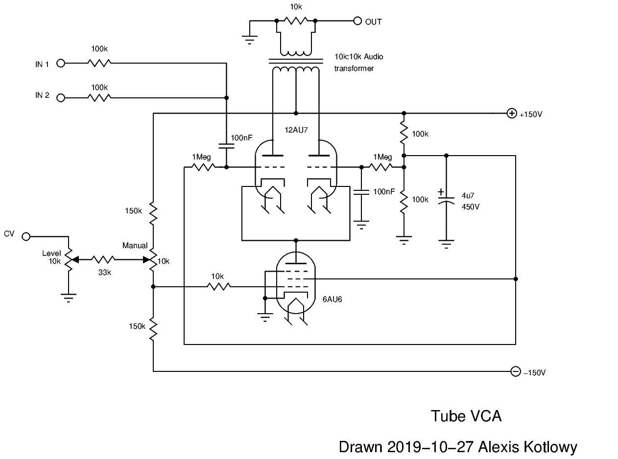
Those familiar with VCA designs may recognise the topology of this circuit. There's a differential pair at the top (12AU7's), with the current through it being controlled by a constant-current sink made from a pentode (6AU6). The current through the pair determines how much gain the circuit has. The current is controlled by the grid voltage of the pentode.
There is the problem of getting the 0V to 10V control voltage down to -10V to 0V, or thereabouts. I found a balanced resistor network works quite well. The idea behind this is to have an equal 'pull' between the top 150k resistor and the bottom 150k resistor. The value of the 10k resistor determines how far down (or up) the signal is shifted (with some attenuation). Replacing the 10k resistor with a pot arranged as shown gives a manual control over the DC offset. The control voltage is applied over the top of the manual control.
Envelope Generator
The envelope generator is a convoluted mess, so let me explain.
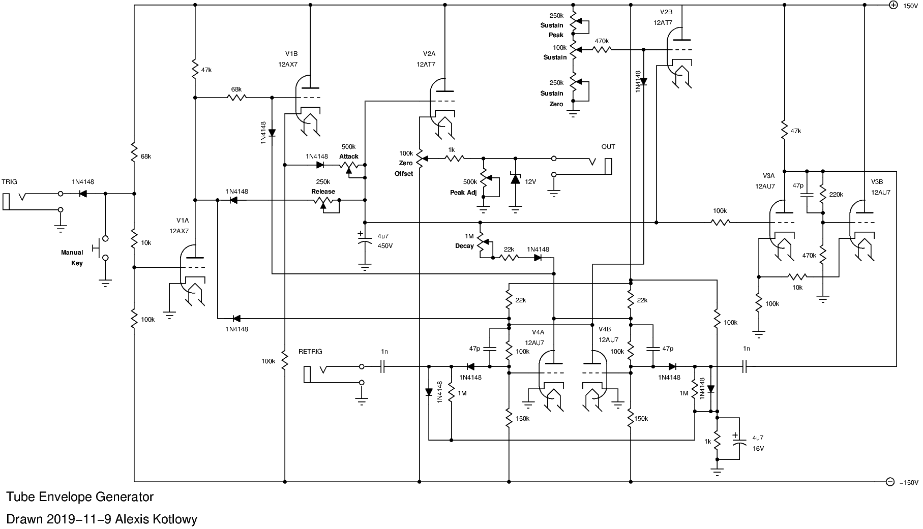
The trigger is a Moog style S-Trig input to keep the control voltages low. Normally the input floats at 20V and the resistor network biases V1A to conduct. This also switches V4B on and V4A off in the flip-flop.
When the trigger input is grounded, the voltage on V1A's grid swings negative, and consequently the plate voltage will swing positive to about 120V. In response, the cathode of V1B will follow the voltage and current will flow through the attack pot into the 4.7uF capacitor.
V3A and V3B make a Schmitt trigger. When the capacitor voltage gets to its threshold voltage through the 100k resistor, it will sharply switch the plate voltage on V3A from 150V to about 110V. This pulse is sent to the flip-flop made up of V4A and V4B, which switches state so V4A is on and V4B is off. With V4A on, the voltage on V1B is pulled to a low voltage via its diode, as well as the 4.7uF capacitor being discharged via the decay pot.
When the capacitor voltage drops below the grid voltage of V2B, it begins to conduct through the cathode which clamps the capacitor voltage at the sustain level. There is a problem with doing this; the decay pot will pull more current through V2B as it's turned up, so the sustain level is a little dependant on the decay level.
The circuit then holds until the trigger voltage is released. When this happens, V1A begins conducting again, which switches V4A on and V4B off. Current starts flowing through the release pot to discharge the capacitor. The circuit will then remain in this state until the trigger input is enabled again.
The retrigger input simply resets the flip flop so the circuit returns to the attack phase. Note this doesn't discharge the 4.7uF capacitor. V2A buffers the capacitor so its voltage can be sent to the output. The output is clamped to 12V (though 4.7V would probably be better). The zero and peak controls should be self explanatory.