 Brian Brocken
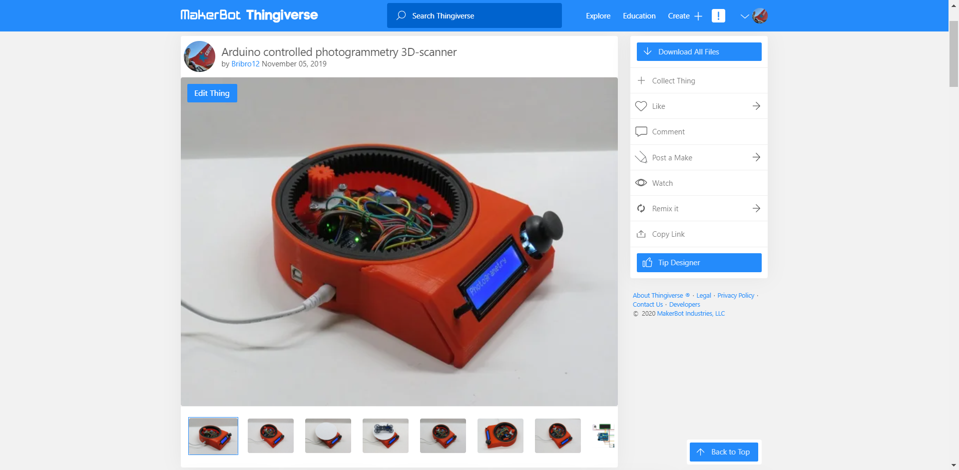
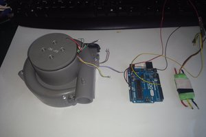
As said before this turntable is a new and improved version of my hand cranked version. A lot of people suggested to me I should put a stepper motor onto it to get some very nice cinematic shots. This is exactly what I did.
I gave it a bit more functionality than just a regular cinematic turntable. I added the possibility to use the turntable to capture photos 360 degrees around an object.
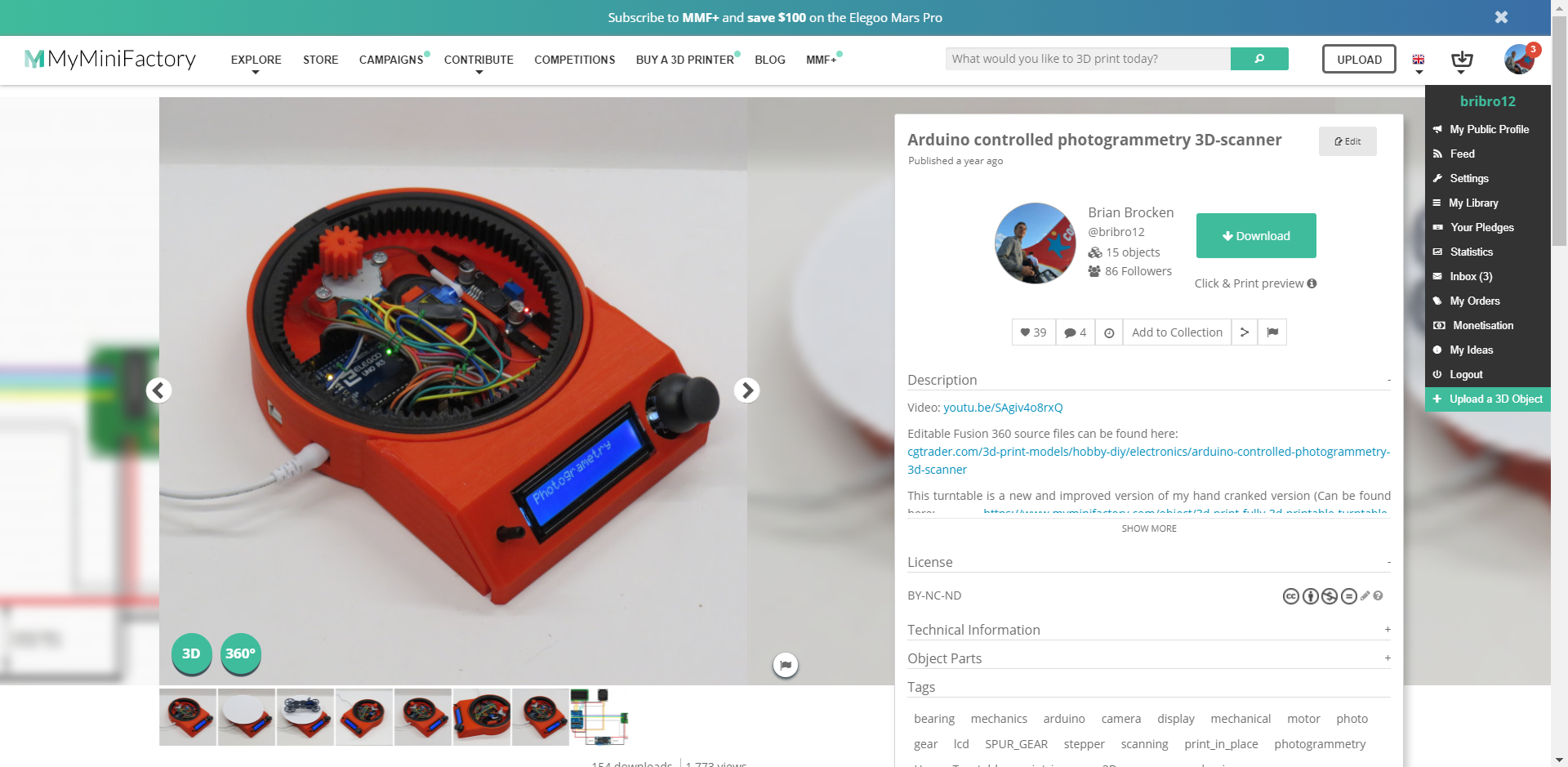
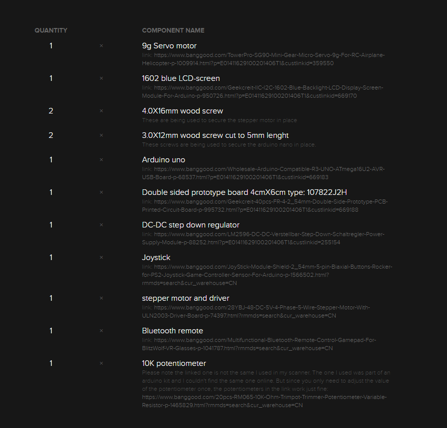
The photos are being taken by a smartphone connected to a Bluetooth remote located inside the turntable. I just used the most straight forward, obvious and simple solution to capture these photos, which was to use a servo to press a button on a Bluetooth remote. I went for this solution due to the fact that Apple products tend to not like the HC-05 and HC-06 Bluetooth modules and refuse to connect to them. I’m sure a cleaner and more durable solution is to use these HC-05 or HC-06 modules and connect them to an android device.
The amount of photo's that have to be taken can be determined by the user, ranging from 2 photo's to 200 photo's. These values can be easily adjusted in the Arduino program. The taken photos can be converted later on into a 3D-model using photogrammetry software. The photogrammetry software I use is Autodesk Recap Photo.
In the second menu you can find the possibility to use the turntable to make awesome cinematic shots of your objects. In this mode the turntable rotates a certain amount of turns at a constant speed chosen by the user ranging from 1 to 17 RPM (speed of the stepper motor).
The third and last menu enables the user to manually control the turntable and bring the plate to the desired position at the preferred speed.
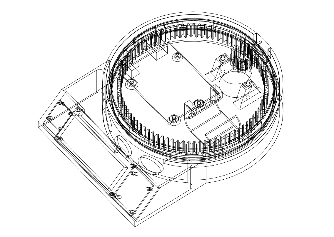
All the mechanical parts of this turntable are completely 3D-printed. The bearing for example is a print-in-place one which works great for this application. The print in place of moving objects adds to the simplicity of the build.
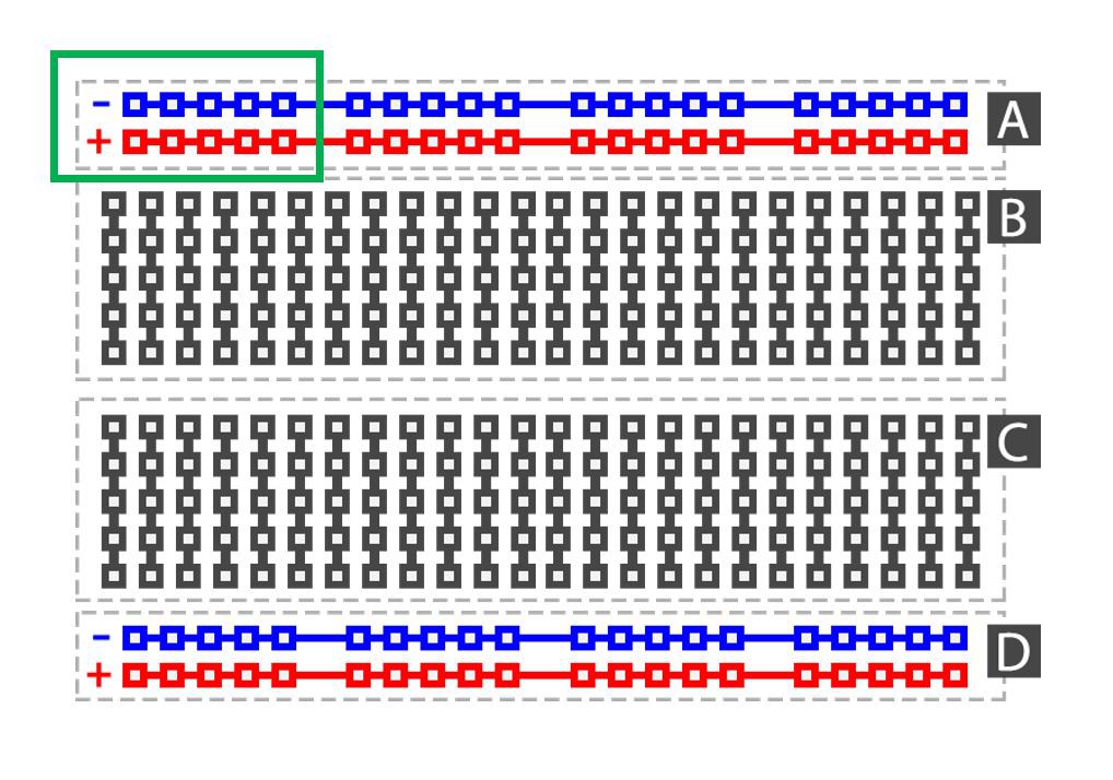
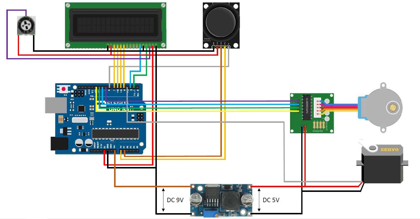
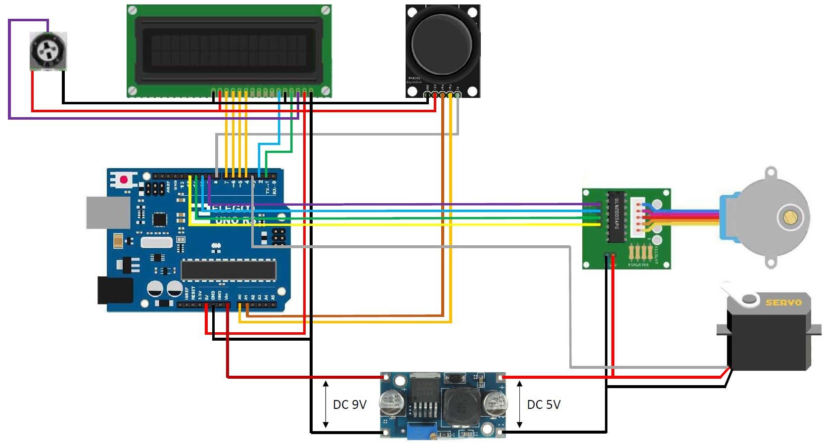
The reason I didn't connect the servo and stepper motor to the onboard 5V regulator and used an extra buck converter is because the stepper motor and servo draw to much current. Everytime the stepper motor rotated or stopped, the backlight in the LCD got brighter and dimmer due to the fluctuation in voltage. Using an extra buck converter takes the load from the 5 volt onboard regulator.
STL and Fusion 360 source files can be found here: https://bbprojects.technology/collections/stl-fusion-360-source-files/products/arduino-controlled-photogrammetry-3d-scanner-files
Video can be found here:


 f3n0
f3n0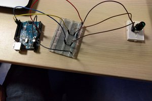
 Leon FAURE
 Michael Ratcliffe
Can this code be used with and lcd keypad shield?