Before I get into the circuits, I should talk about logic levels. In most transistor-based logic circuits, Boolean 0 and 1 are conveyed with high and low voltage levels, such as nominal 0 V and +5 V in TTL.
This convention works fine with relays too. However, leaving the coil not connected (NC, high impedance, high-Z) is logically the same as connecting both sides of the coil to ground. This is sometimes called a floating zero. It turns out that implementing logic with NC and supply rather than ground and supply is a bit simpler, at least for SPST relays.
Mixing ground and supply as inputs to relay logic is also a great way to accidentally create a short-circuit.
These facts encouraged me to take an approach where logic outputs are either NC or connected to a source. Inputs are usually a single coil and are sinks. This isn't the only approach, and circuits can be simplified by violating this rule of thumb. It still seems a good idea to adopt a floating zero.
So, let's begin.
The relay:
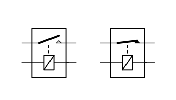
On the left we have symbols for a normally-open (NO) relay and on the right a normally-closed (NC) relay.
The non-inverting buffer:
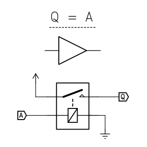
The coil is connected to ground and input A. The switch is connected to supply and output Q. When the coil is energized by current from A flowing to ground, the coil energizes and closes the switch. Supply voltage is then available at Q. Summarized, when A is NC or ground, Q is ground. When A is source that can drive a coil, Q is that source.
This buffer has two useful properties. First, the circuit's input and output are always electrically isolated, preventing a supply connected to Q further down the circuit from flowing back into input A. It is also an effective "amplifier". When connected directly to supply voltage, this circuit can drive any number of relay coils in parallel, up to the amp rating on the relay's switch. This is necessary for some circuits which can only source a limited amount of current.
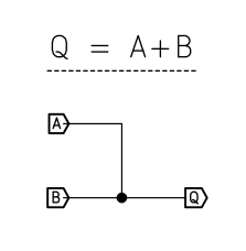
Logical OR:
In many cases, a simple wired OR suffices. If all the inputs are not connected, the logic level is 0. If any are connected to +V then it is logic 1:
Sometimes it is necessary to isolate the prior stages. The above buffer can easily be chained to provide an OR gate:
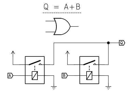
An arbitrary number of inputs is possible here.
Logical AND:

With this circuit, if Q is only true when B and C are both true as well. This circuit can also be chained for an arbitrary number of inputs. Note that A is simply switched through, which is a potential hazard.
In the next post, I'll look at inverters.
Discussions
Become a Hackaday.io Member
Create an account to leave a comment. Already have an account? Log In.