 Patrick Van Oosterwijck
I think it was originally in September of 2018 that @Prof. Fartsparkle suggested to me right here on Hackaday.io to make a project like this as a "successor" to the #wESP32. Since at the time the wESP32 wasn't even released yet, that seemed a bit premature to me. :) But I liked the idea enough to do a good brainstorming session. I don't see it as a successor so much as a nice addition to the PoE products that are available to makers.
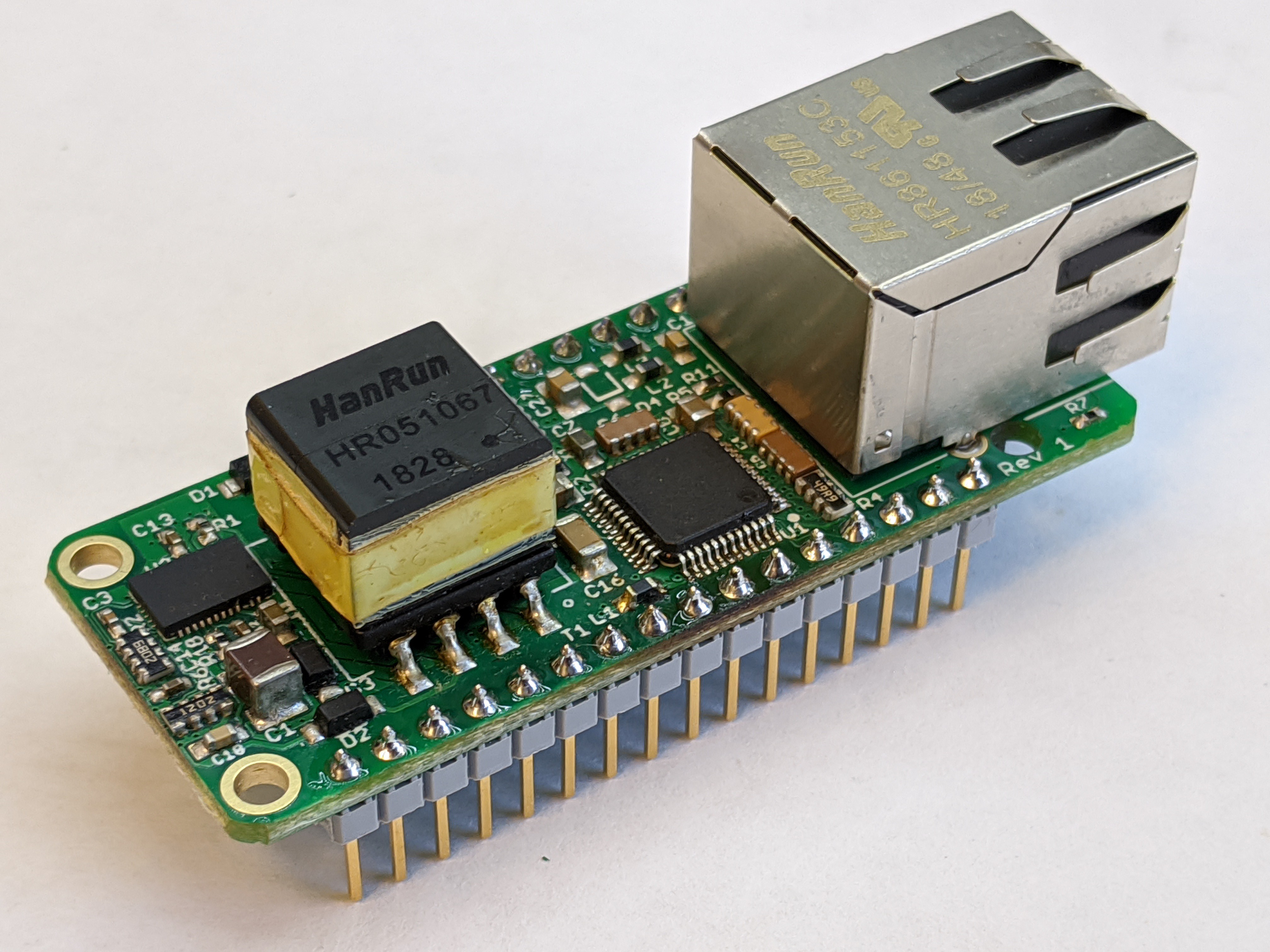
There were a couple of potential snags in making a PoE FeatherWing. The first is that the Feather system didn't intend for FeatherWings to back power the main board. That doesn't mean that nobody has done this tough. :) I think many Feather boards now include a diode to prevent back powering the USB port, and for those there is no issue. There are some that don't include this circuitry though, so the problem had to be managed carefully.
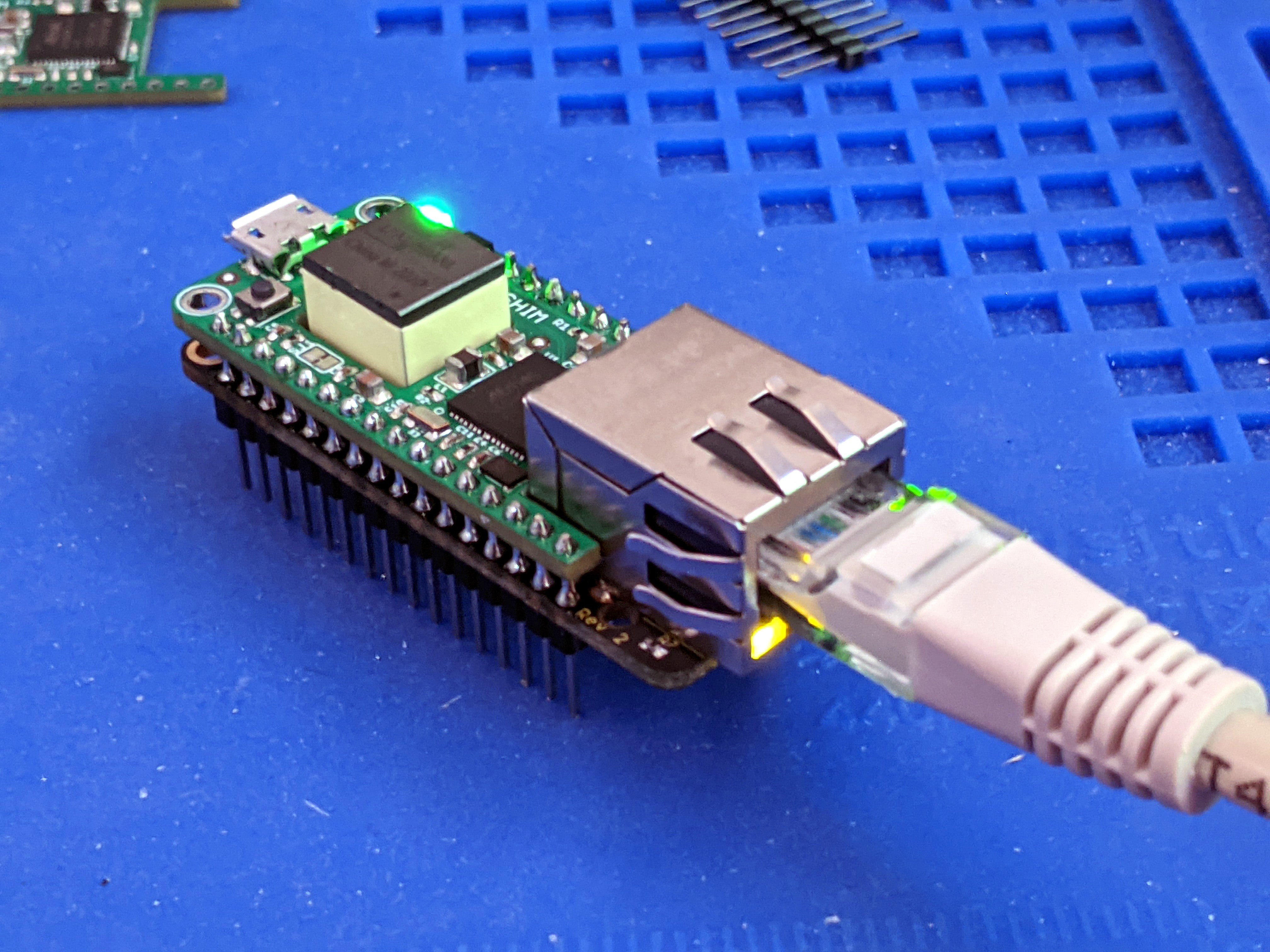
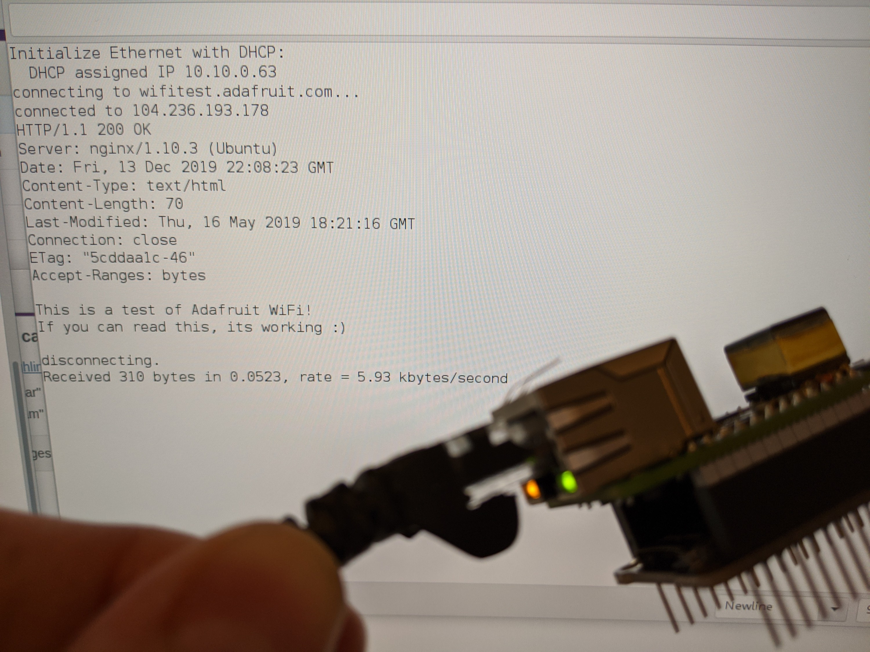
I do this by putting ~4.5V on the USB pin, instead of 5V. Since the flyback converter of the PoE supply has a diode rectifier on the output, it will just not provide power if there's a voltage higher than its own output on the USB pin already. I've tested this with a Feather M0 Adalogger which does not include a diode, and my USB port was not blown up. :)
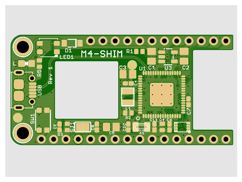
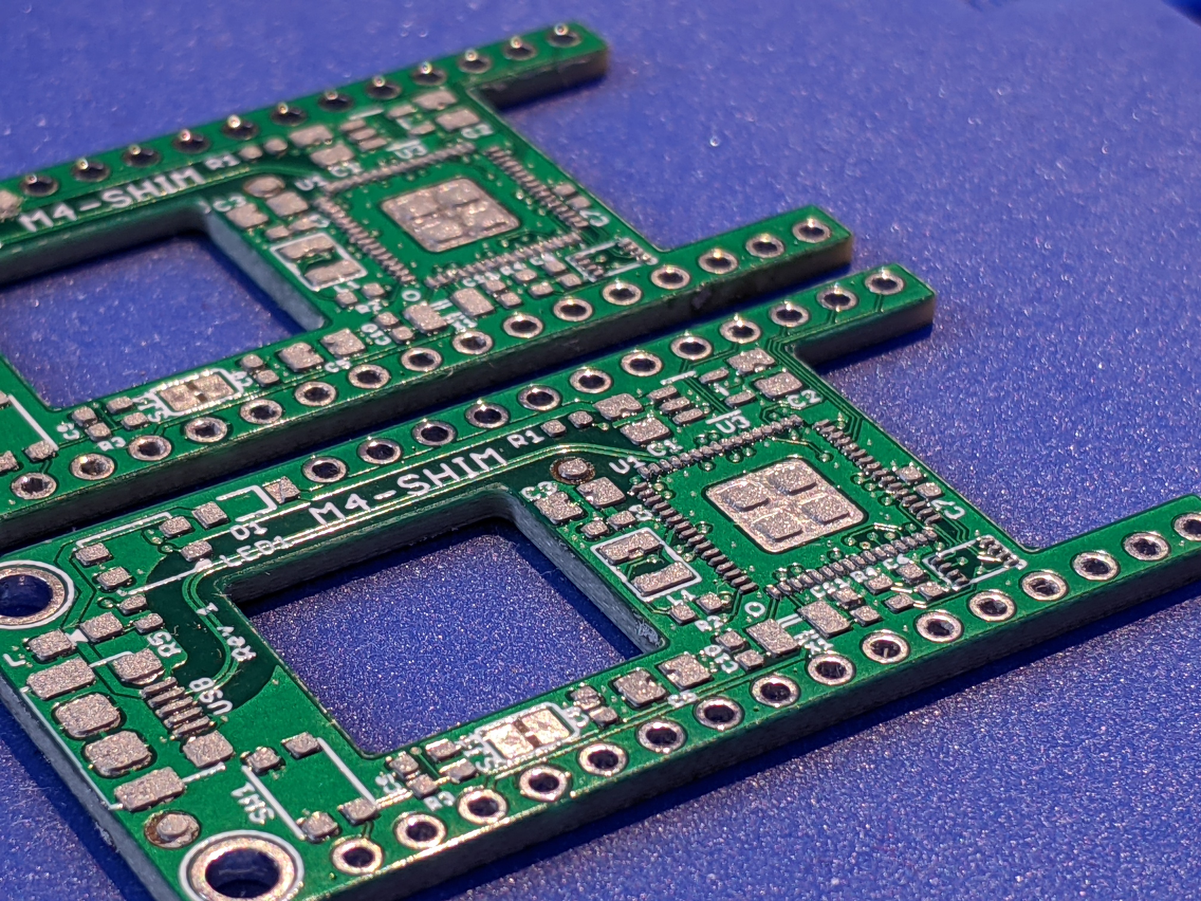
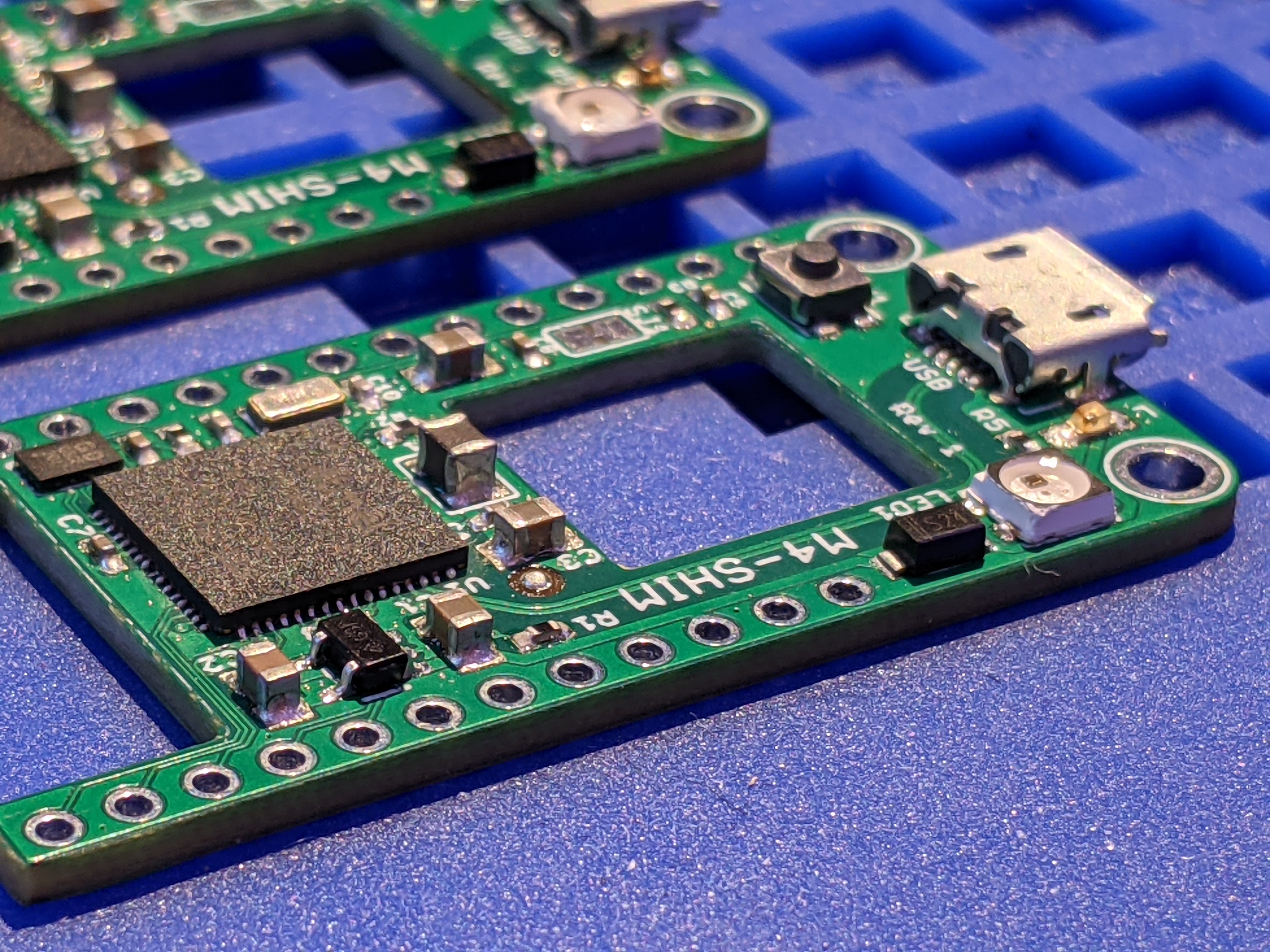
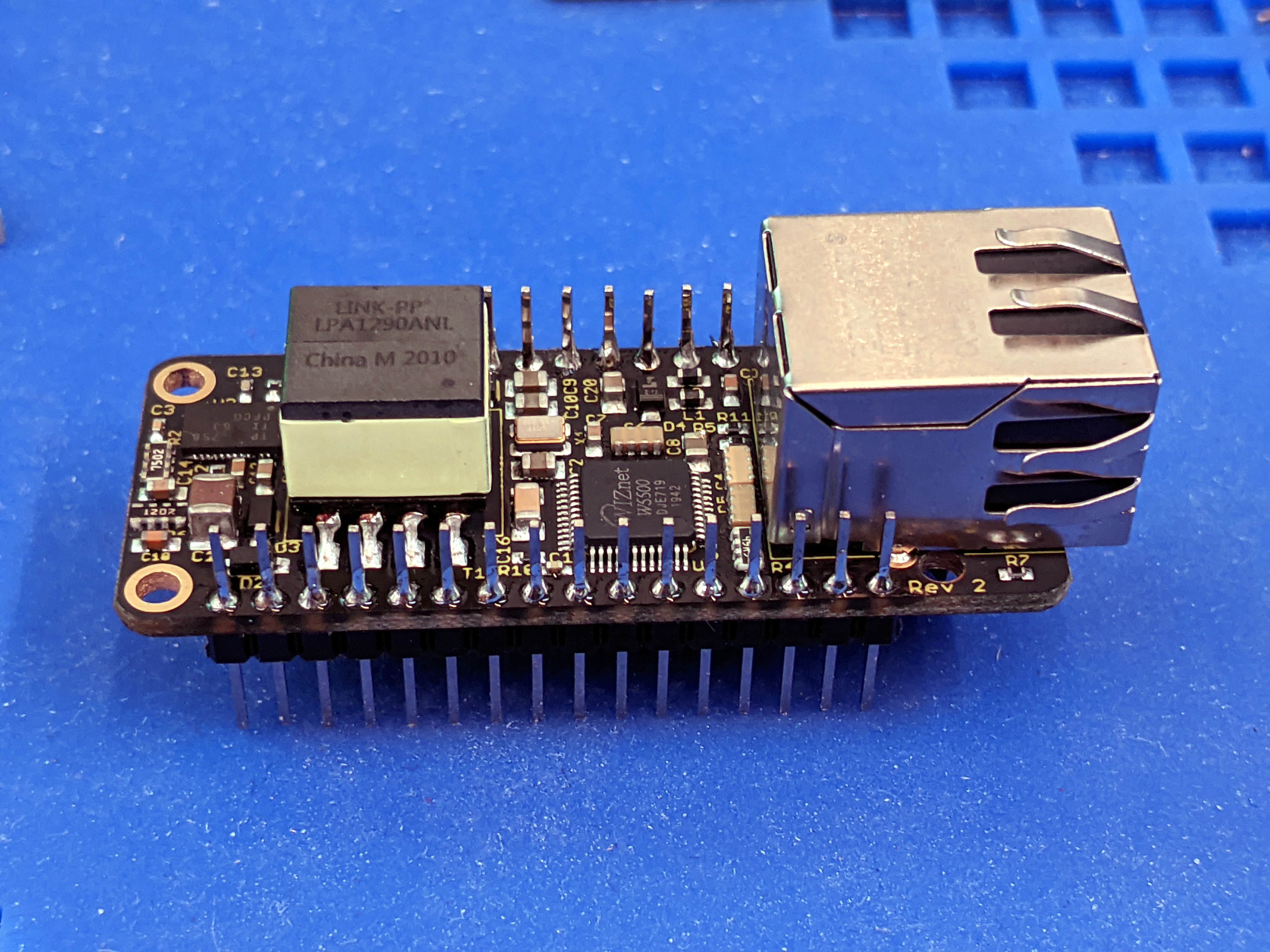
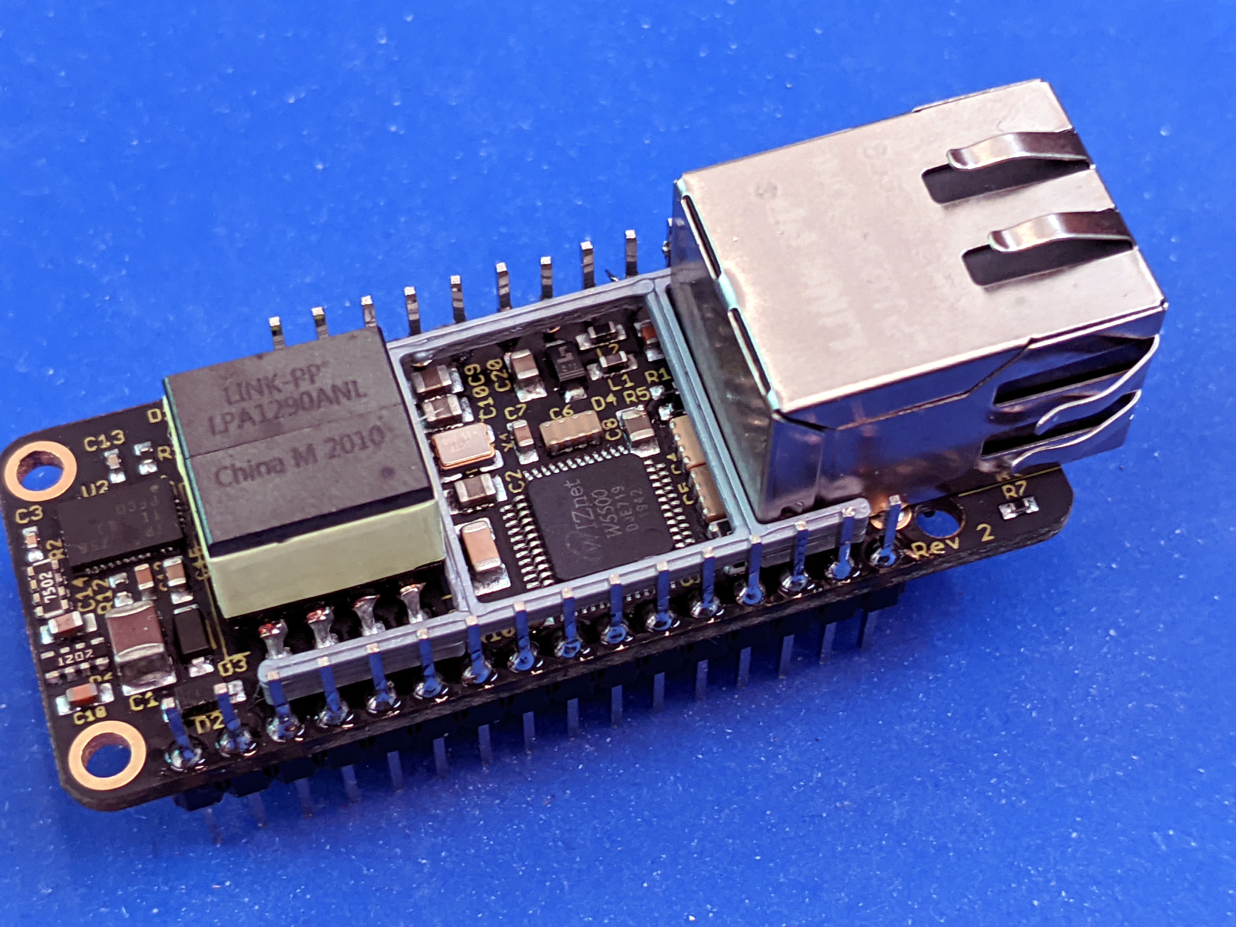
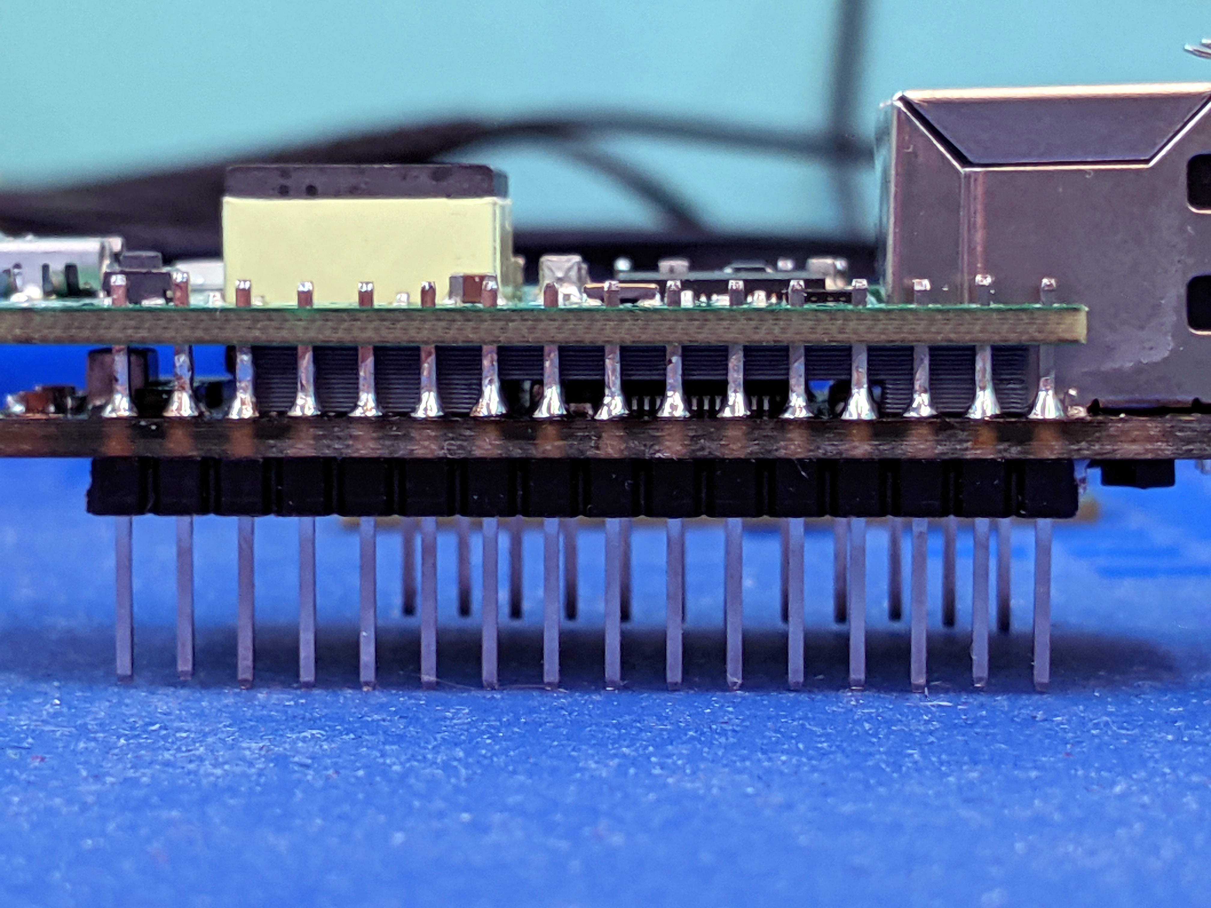
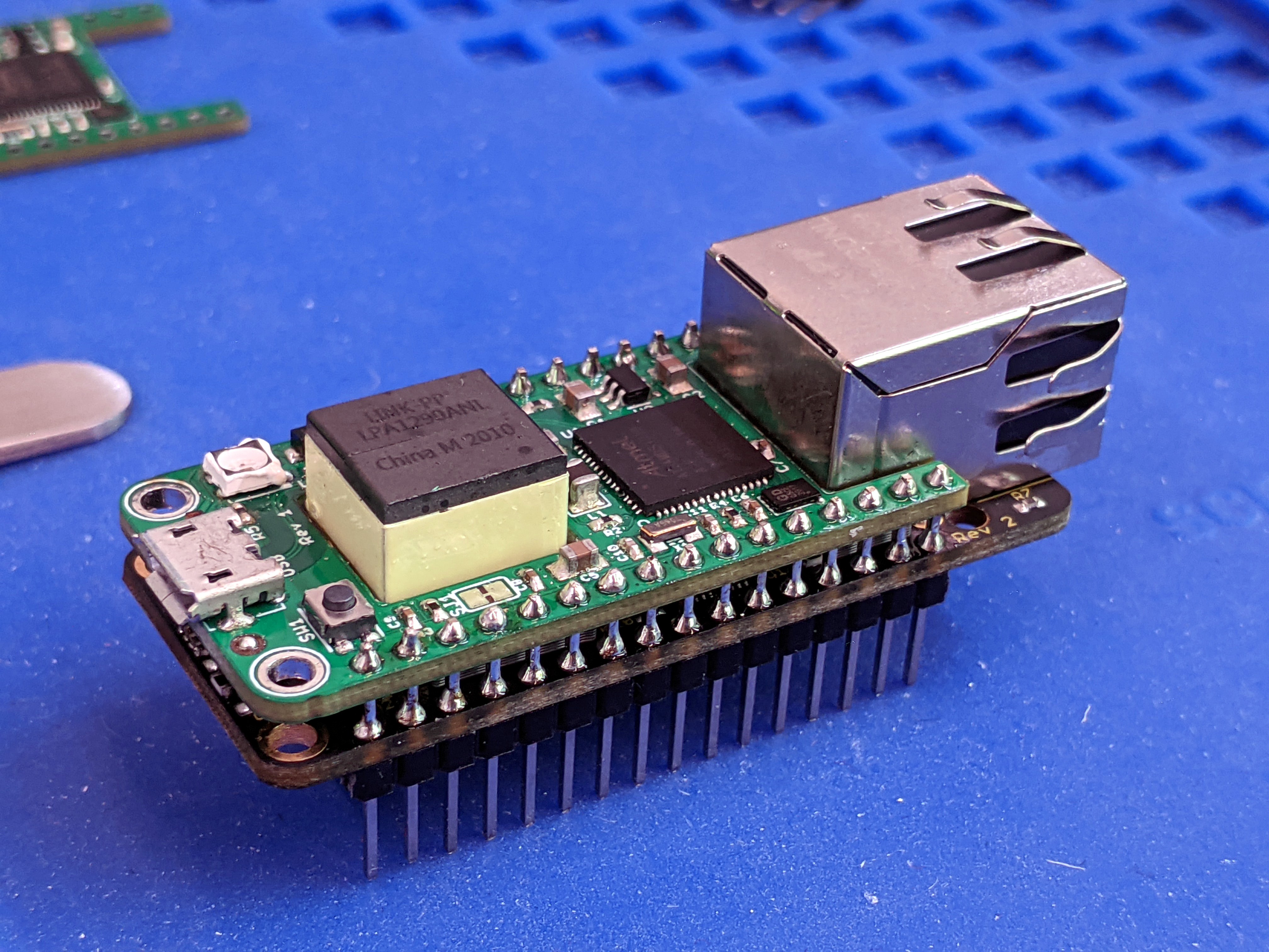
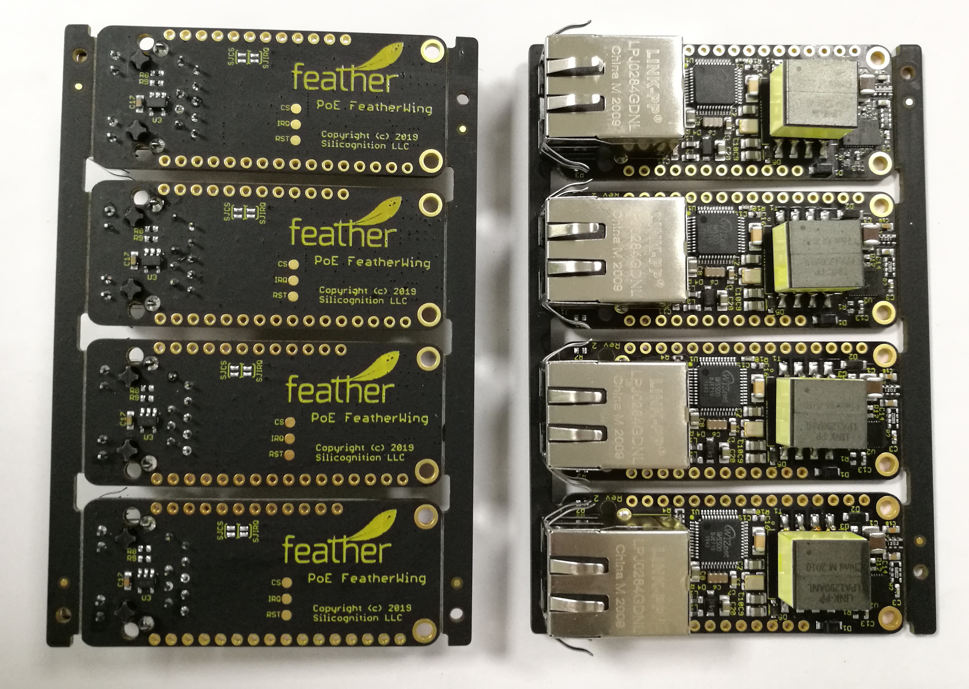
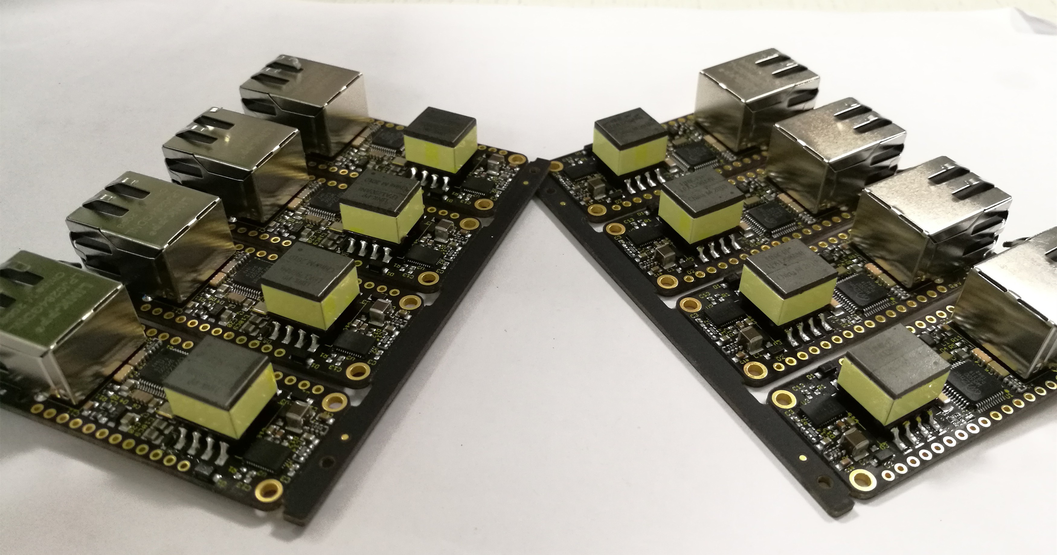
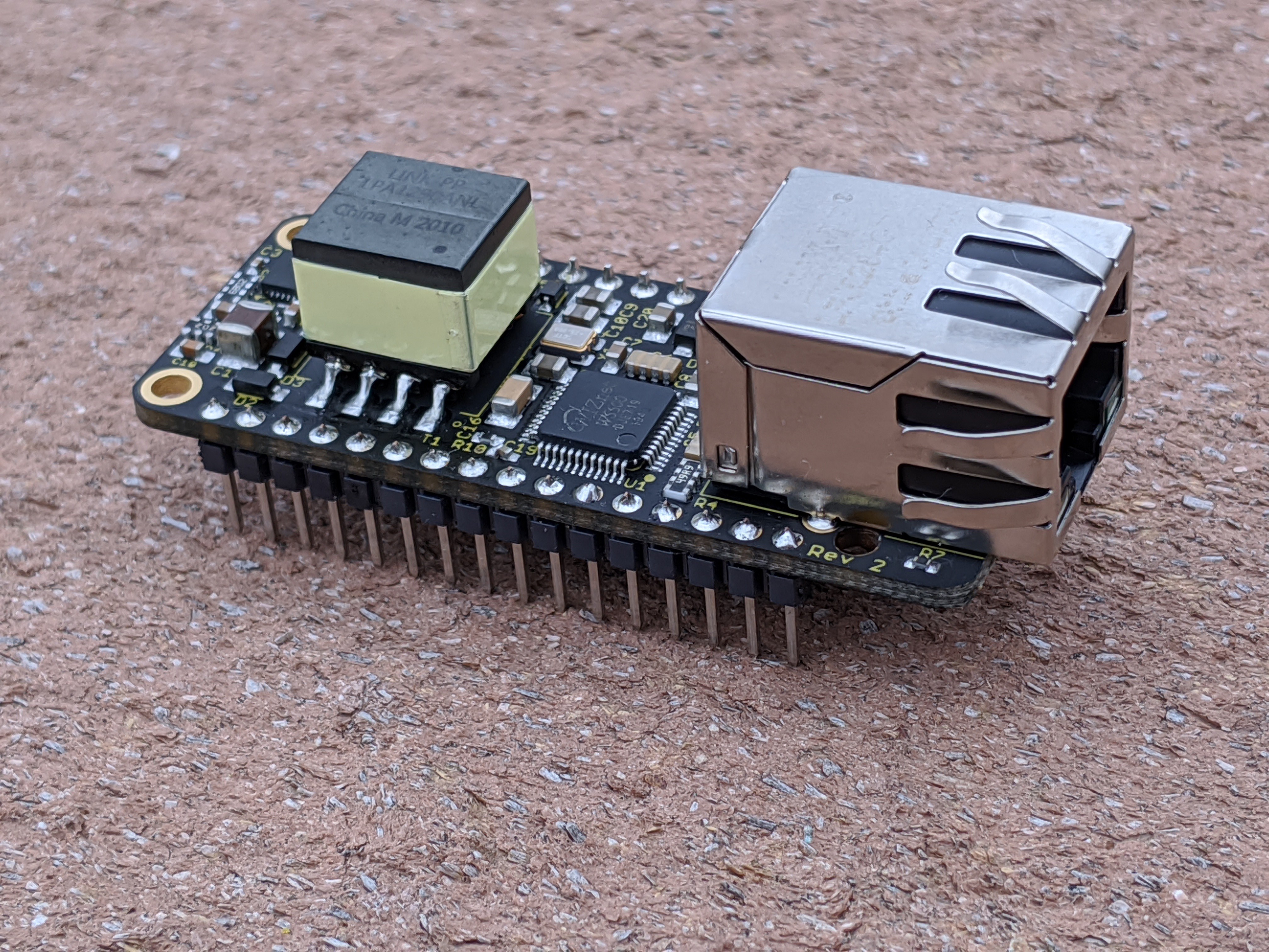
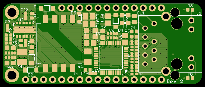
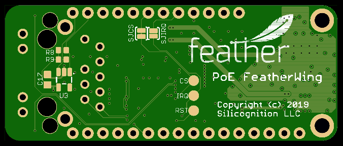
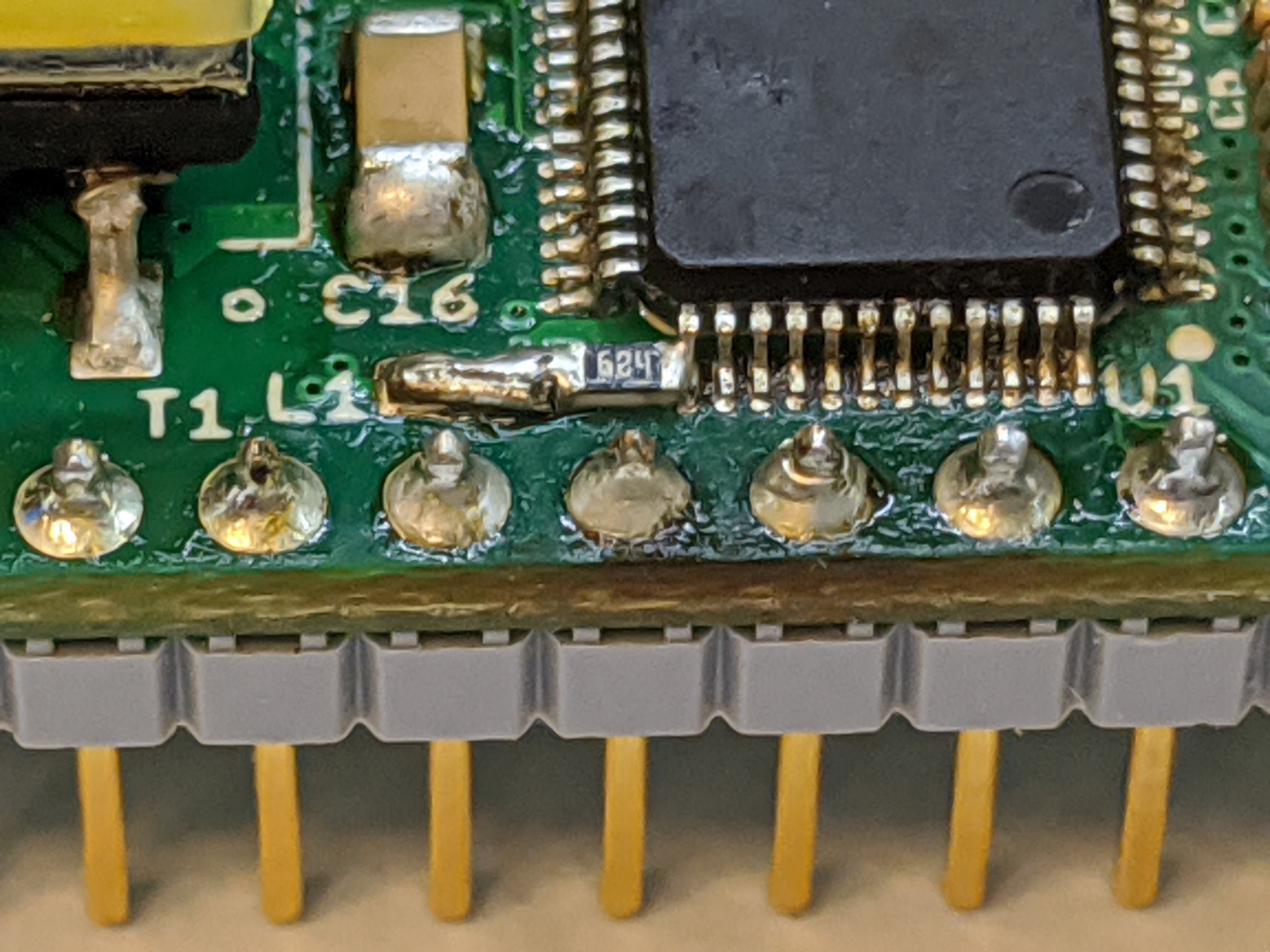
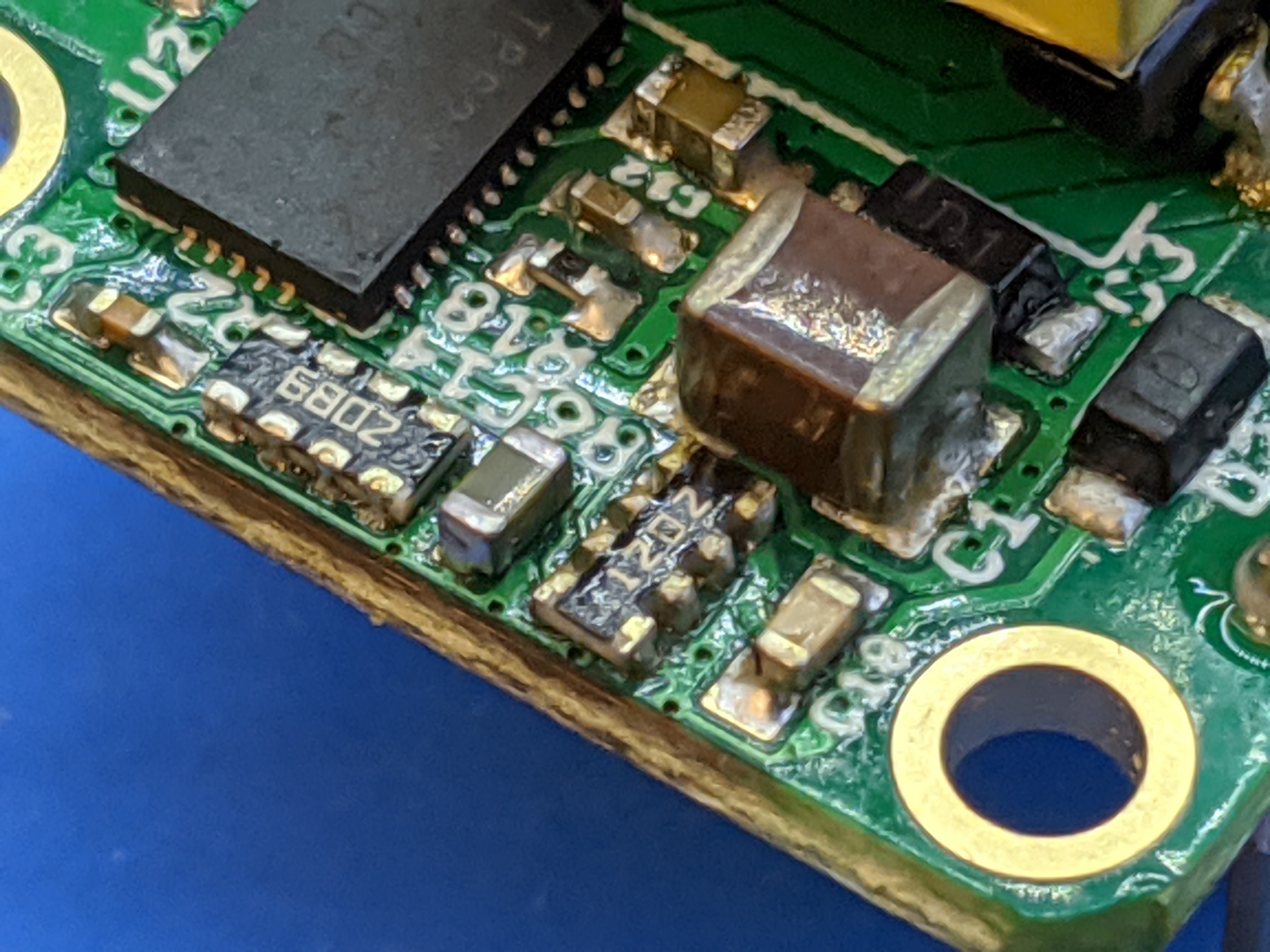
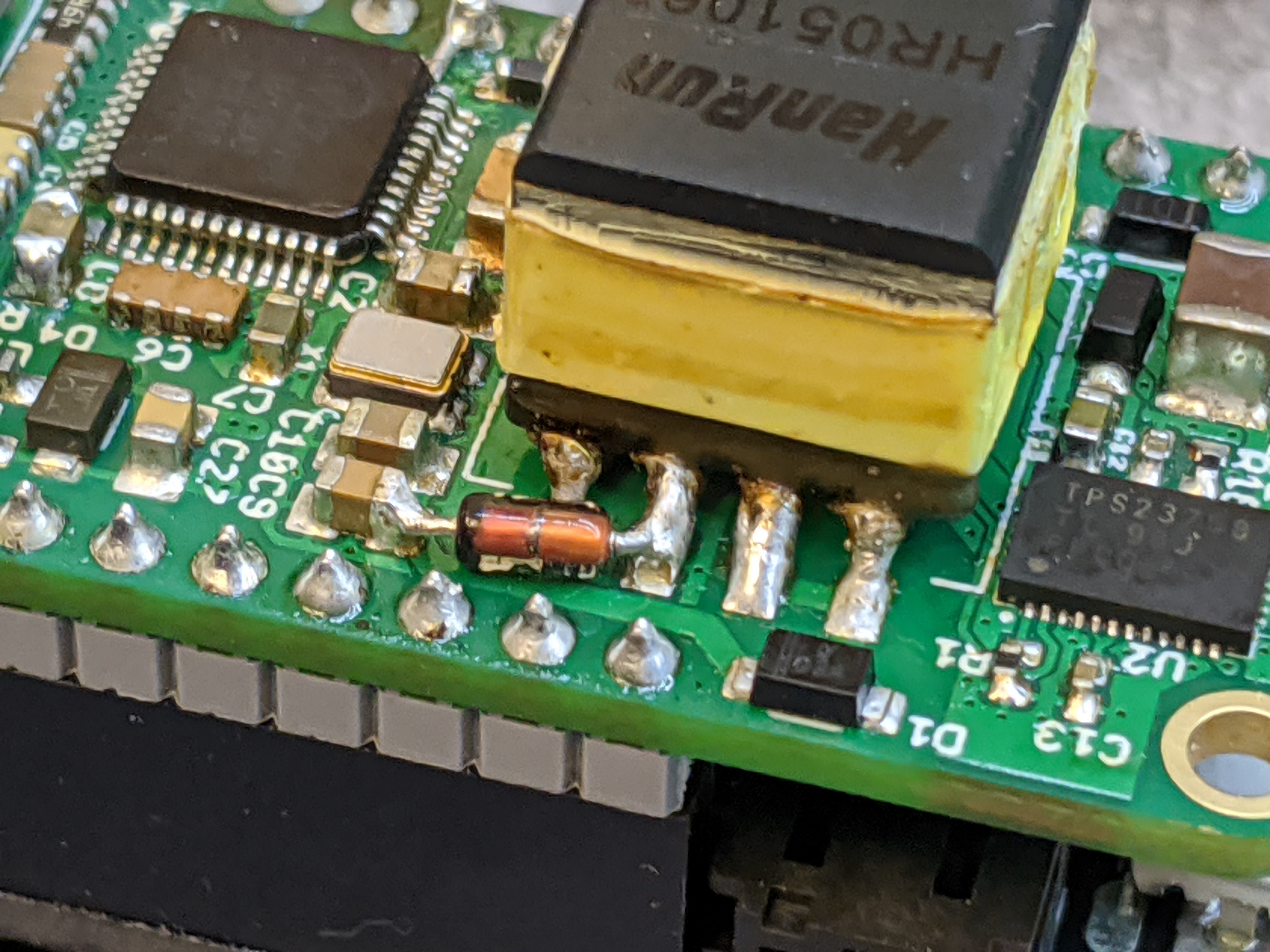
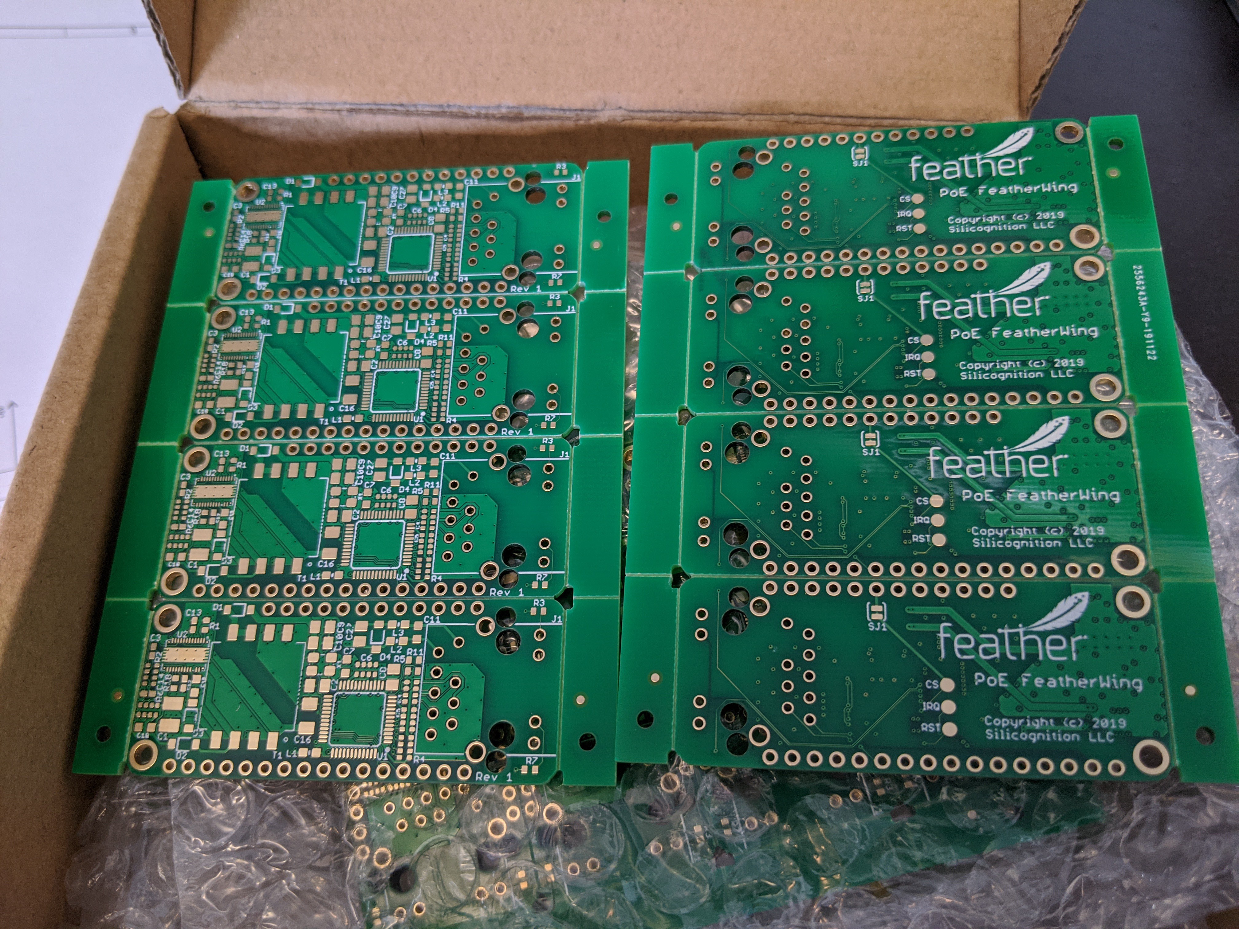
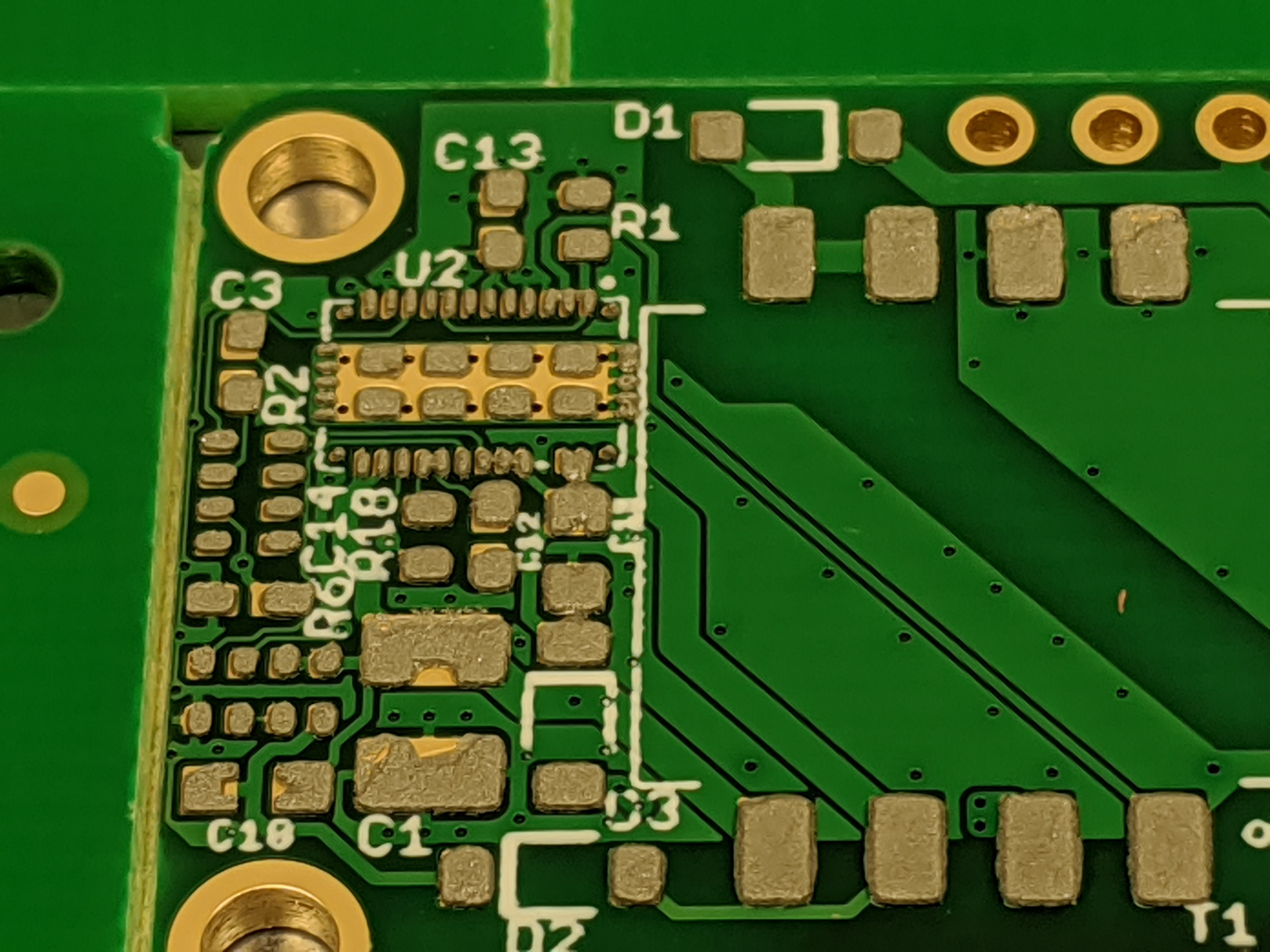
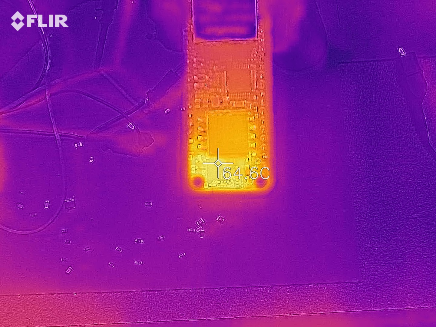
The second potential snag was of course size. Feather boards are tiny, and Ethernet jacks and flyback transformers are not. It took a 4-layer board, going to 0402 parts from my usual 0603 (really not an issue nowadays) and using plenty of resistor and capacitor arrays versus individual components to get the needed density. Initially I wanted to keep all components on one side, and I succeeded in this for the main functionality if you don't count the (optional) 24AA02E48 on the bottom. But since my CM has no issue or extra charge for double sided components, it's not really an issue.
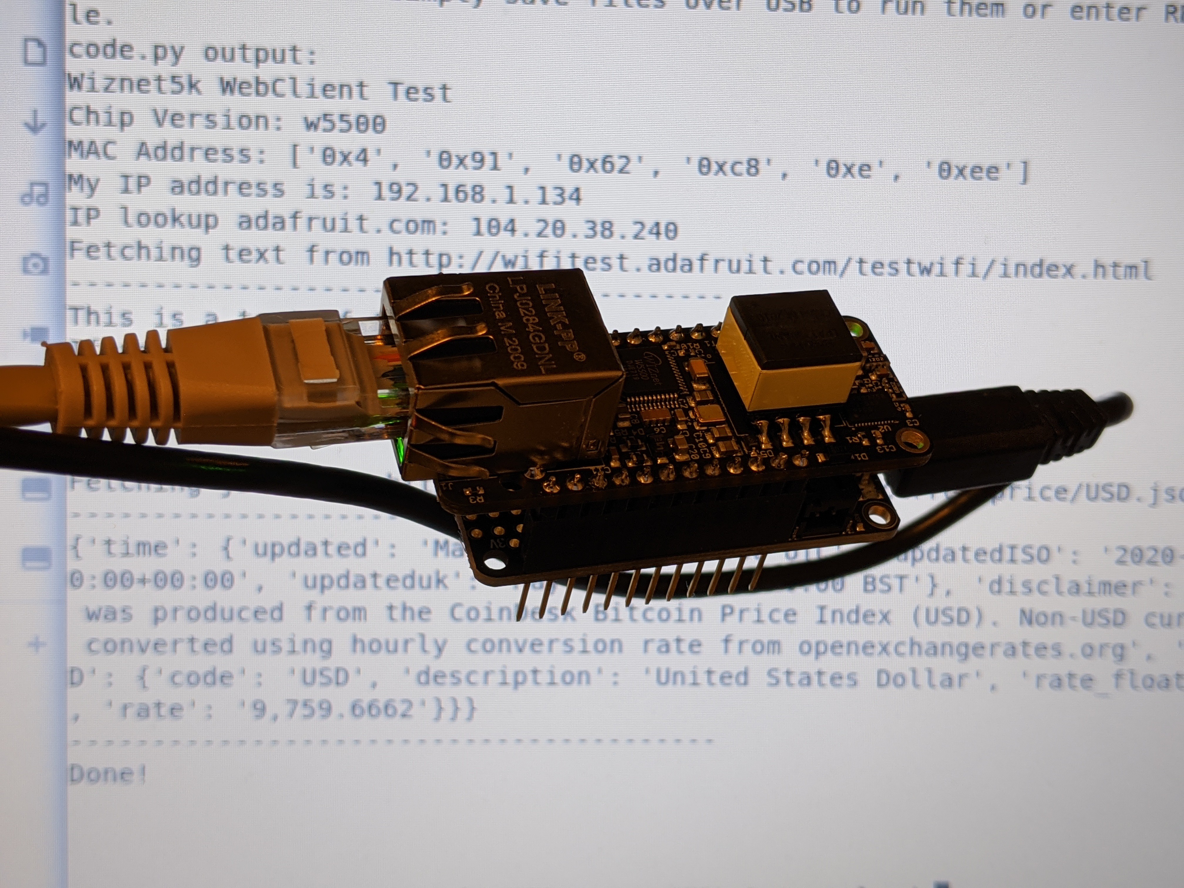
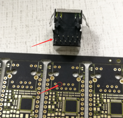
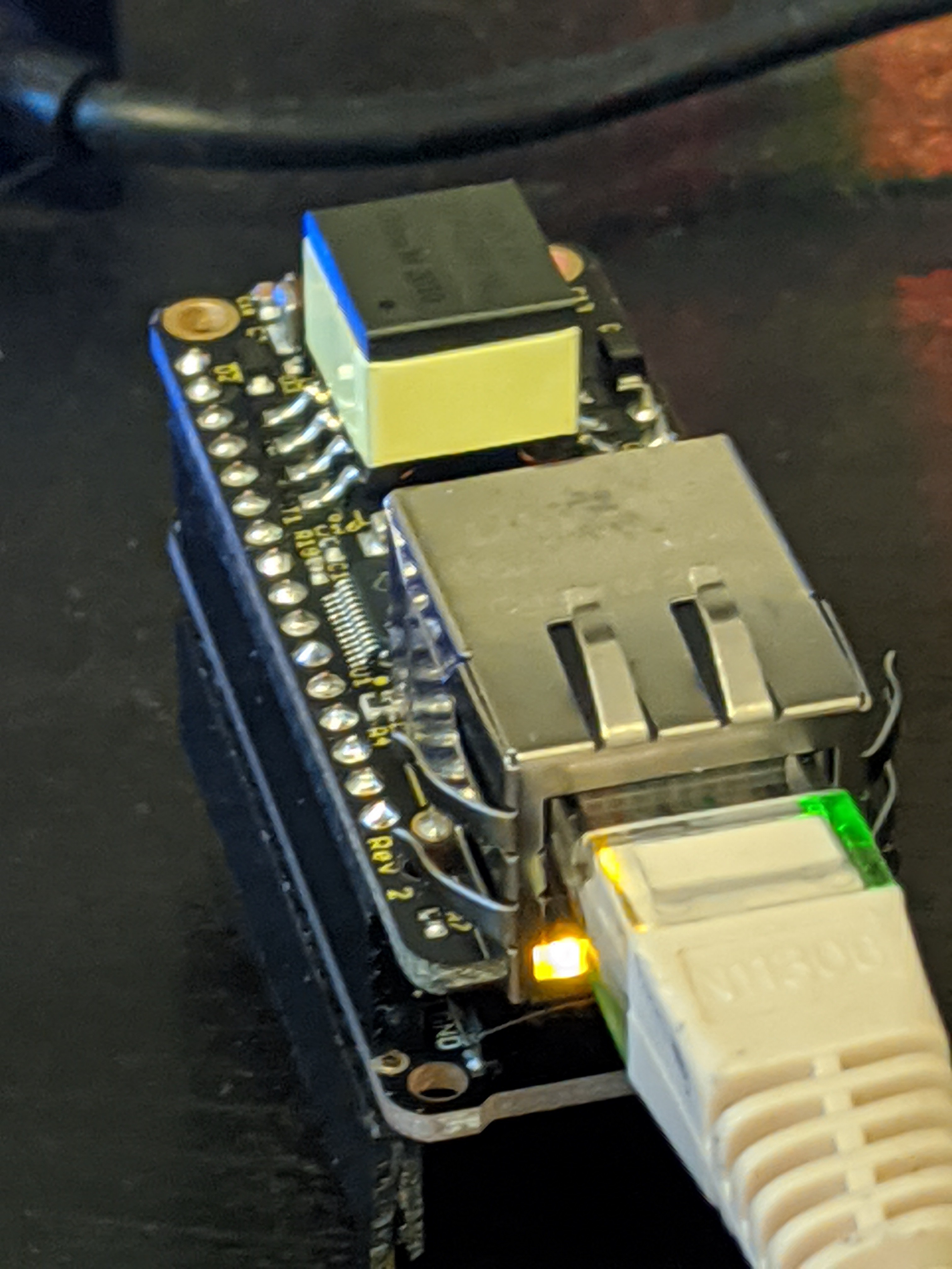
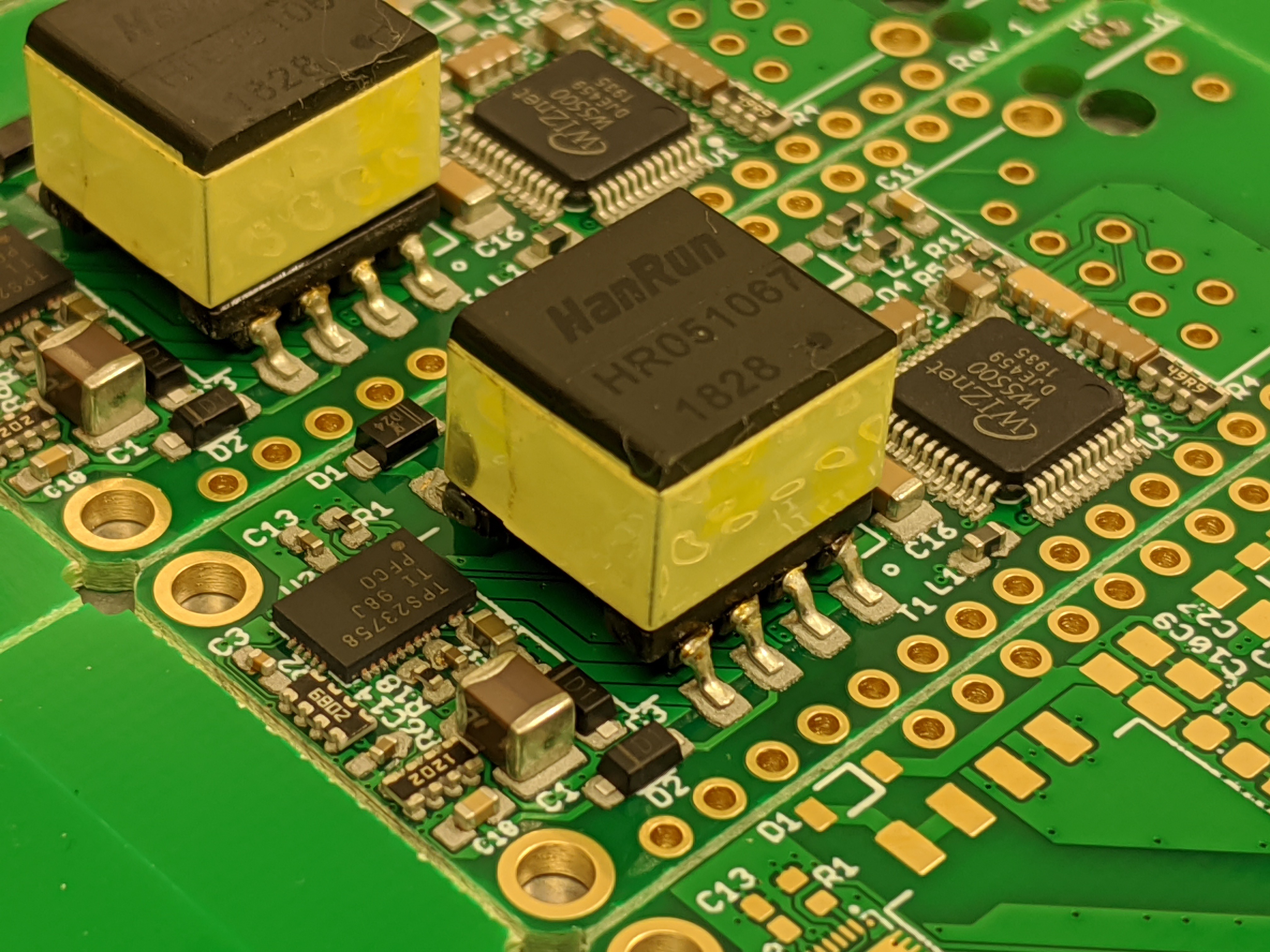
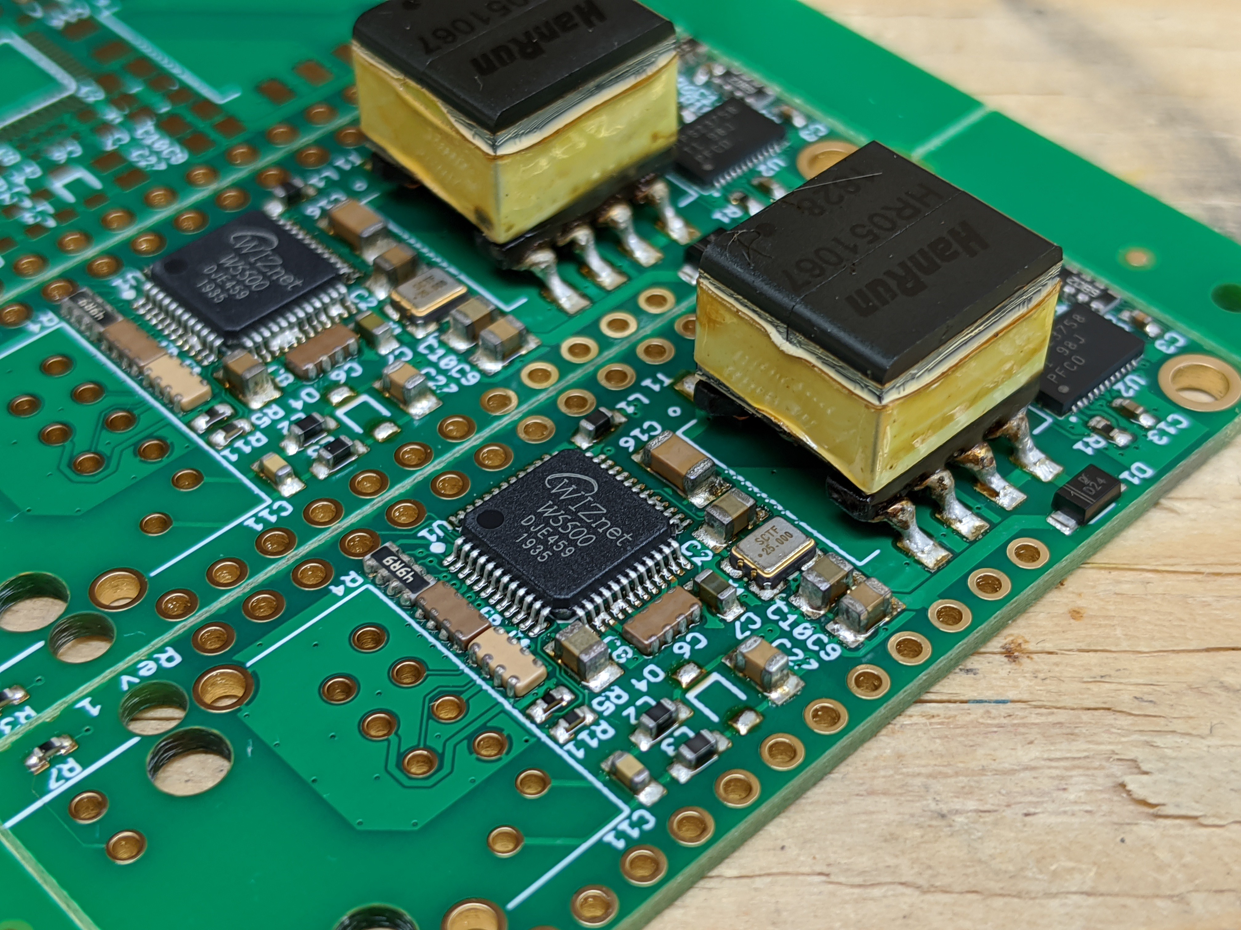
I used the WIZnet W5500 just as it is used on the Adafruit Ethernet FeatherWing, so it is fully compatible with all the existing software out there. I also added a 24AA02E48 chip to fix the annoying issue that WIZ5500 chips don't come with a MAC address built-in.
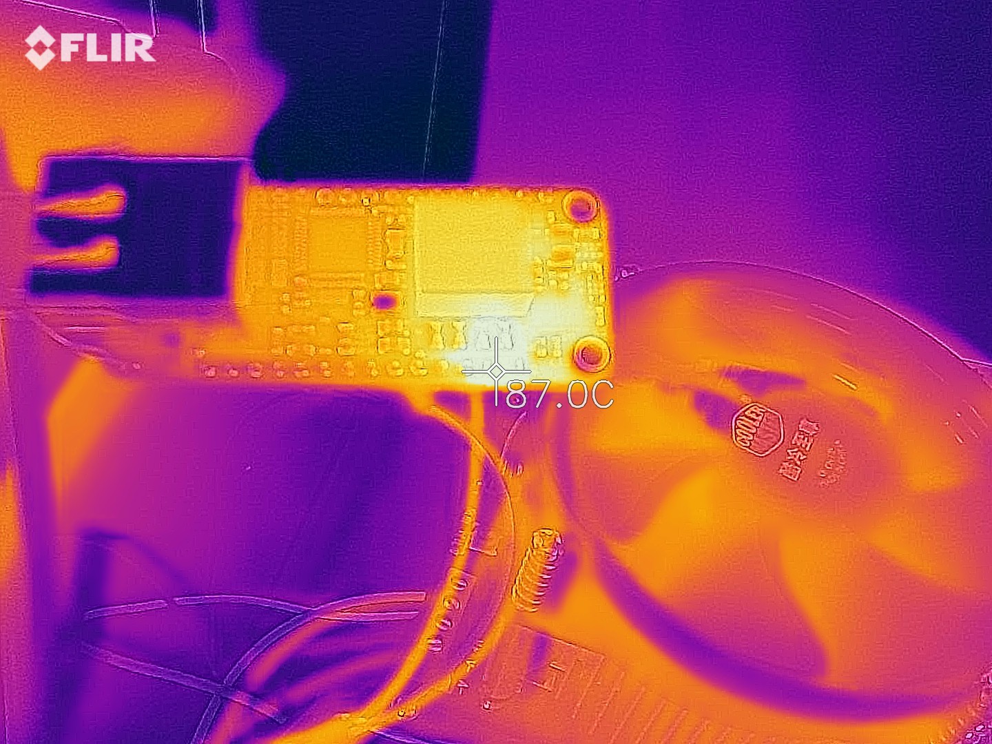
For the PoE side of things, this had to shrink significantly from what I was using on the wESP32. To that end, the design was built around the TI TPS23758 instead of the Silicon Labs Si3404A. The chip is slightly bigger, but it implements primary side regulation using the flyback transformer's auxiliary winding, making it possible to drop the huge opto-coupler and all the circuitry around the secondary side shunt regulator. I also used a 5W instead of the wESP32's 13W flyback transformer as I had done on the #LiFePO4wered/ESP32, since Feather systems don't tend to be power hungry, and the tiny size would just not allow such power while keeping it isolated. In the end, you can confidently get 3W out of it, 4W is possible but pushing it. Not bad since the normal USB power into a Feather system is limited to 2.5W.


 Brian Lough
 Mastro Gippo
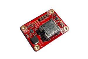
 Tony
Tony
Hello! This project is excellent! Is there a 3d model available anywhere for us to design an enclosure around?