Close
0%
0%

PHYLLO

Or how to create animated flowers with LED and 3D-printing

Public Chat
Similar projects worth following
Blooms and interactive sculptures made open source

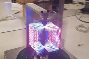
Ever heard of phyllotactic spirals ? John Edmark was inspired by these naturally occurring leaf patterns to create a series of sculptures he called “Blooms”.

This is the starting point for our project, Phyllo, that you can follow on our students' blog.

As John Edmark explains in this instructable, he spins a Bloom under a stroboscopic light to create the illusion of a flower blooming.

In our project, we will build upon this and:

  • Color each petal individually from the inside with stroboscopic LEDs.
  • Play colorful animated patterns on the sculpture (such as falling or rising petals, lines, spirals, rings…).
  • Display animation patterns across neighbouring phyllos: when two sculptures are close enough, they can synchronize and the animations will propagate from one to the other, creating globally coherent phyllotactic patterns.

Here are some 3D simulations to give you an idea what it could look like: 

We will keep you posted as the project moves forward. Stay tuned ! You can find any information or update on our logbook. Feel free to comment, any suggestion or idea is much welcome :)

  • 1 × BOM not ready yet, but stay tuned on our blog : https://rose.telecom-paristech.fr/2020/tag/phyllo

  • Taking full control on our 3D model

    Alexis12/10/2019 at 00:43 0 comments

    We discussed in our post Generating 3D Models  the script I wrote to generate the 3D model of our phyllotactic sculpture. In this script, I start by generating a polyhedron made up of quadrilaterals arranged in a phyllotactic pattern:

    Then, my script takes as input a 3D model of a petal and copies it on each quadrilateral:

    The 3D model of the petal I use is taken from John Edmark's model

    One problem with this method is each quadrilateral is different, which means I had to slightly deform each petal to fir the quadrilateral's shape. Figuring the exact 3D transformation to accomplish this seemed a little too time consuming so I used lattices in blender, which are a way to deform objects according to a 3D grid. It turns out the result is not perfectly clean, and leaves small gaps between petals:

    We also noticed the petals on John Edmark's model are not all identical: they all have slightly different orientations, and therefore appear to slowly rotate on themselves when animated.

    This gif used John Edmark's model. You'll notice the rotating effect by following a single petal while it descends.

    Using identical petals leads to a much less interesting animation. These two problems led me to abandon this method of generating petals, and procedurally generate them instead.

    In order to do this, I chose to use NURBS, which are a way to generate smooth surfaces using a 2D grid. This is also what John Edmark used to generate his petals.

    Reproducing the petals will likely take some time, so for now I only generate simplified petals. Manually modelling the petals with NURBS surface wouldn't be that hard, but generating them within a script from a quadrilateral given in input, and being able to control their orientation is a whole other story...

    This petal was generated using only 16 points.

    Controlling the orientation of this simplified petal is quite simple : I only have to move around the upper polygon.

    This new method allowed me to generate a clean model of our sculpture, with a nice rotating effect on each petal:

    I'll probably attempt to model more complex petals during the winter vacations, so stay tuned for that !

  • The PCB puzzle

    Alexis12/10/2019 at 00:42 0 comments

    We made a few major modifications in our design : it turns out flex PCBs aren’t possible. Even though everything isn’t quite decided yet, here is a summary to clarify the situation. I will keep you updated of any major modification :)

    General design

    A Phyllo is composed of three parts:

    • a fixed base,
    • a rotating half sphere placed on this fixed base serving as support for the lighting of the sculpture,
    • a hull made of petals that covers this sphere.

    A Phyllo has 78 petals that can be illuminated individually (8 spirals with 6 petals lit by spiral arms, or 13 spirals in the other direction). The remaining petals are the tiny petals at the top, and they will all share a common illumination.

    The diameter of the inner sphere measures about 15 cm, the base is about 20 cm.

    From there, when one is interested in the projection of the petals on the inner half sphere:

    • the smallest petal that can be illuminated measures 0.83 * 0.79 * 1.04 * 1.14 cm.
    • the centers of the petals are at least 0.97cm apart.

    Organisation of the PCBs

    Each Phyllo will have:

    • 1 fixed PCB in its base,
    • 1 rotating PCB near the equator of the inner half-sphere,
    • 62 PCB-petals to illuminate the 62 largest petals,
    • 1 PCB, called "Top PCB" to illuminate the remaining 16 petals as well as the top of the structure.

    The PCBs-petals are therefore placed inside the half-sphere as in the picture below:

    The top PCB will have a star-like shape as in the image above. 

    The PCB-petal shape is yet to be found. If we use the shape of the image, we will have to make a bigger Phyllo in order to have enough room on the PCB for all the components. We had the idea of T-shaped PCBs as in the picture below, but according to Alexis, it will be too complicated to wire.

    We also had the idea of overlapping PCBs for small petals and using printed tubes to conduct the light, like in the picture below. But the possibility of wiring is still under discussion.

    Any comment or suggestion will be much welcome !

    Functional architecture

    The following diagram summarizes the functional architecture of a Phyllo:

    Details

    Fixed part

    The fixed part of the Phyllo will contain the motor, the ESC, the battery, the power transmission device and the fixed PCB. The fixed PCB will include:

    • an IrDA transceiver to be able to communicate with the rotating part of the Phyllo,
    • a connector for the battery,
    • a charging circuit of the battery,
    • a 3.3V regulator,
    • a USB port to recharge the battery (and the circuit that goes with it to feed the Phyllo while the battery),
    • an electromagnet to be detected by other Phyllos
    • a CPU,
    • a SWD port for debugging.
    Power transmission

    To clarify a previous post, here is a shema of the device for power supply transmission from the fixed part to the moving part is based on the use of ball bearings as follows:

    The idea is to transmit one terminal of the battery through the motor ball bearing by soldering a wire to the motor and another to the axis. To pass the other terminal, use two other ball bearings, electrically isolated from the shaft by a rubber sheath.

    Detection of other Phyllos

    We are still discussing how exactly to go about detecting other Phyllos. We discussed several possibilities in [this previous post]. Our favorite lead then included using IR emissions to determine the direction of a neighbouring Phyllo, but it has since then become apparent that IR reflections would be a serious problem. More on this in the following post.

    Rotating part

    Rotating PCB

    The rotating PCB is the one where all the logic of the Phyllo is happening. It includes :

    • an IrDA transceiver for communications with the fixed part,
    • a hall effect sensor (and an optical sensor just in case) to detect the angular position of the motor and to be able to play animations in a chosen direction,
    • a module wifi to be able to communicate between the Phyllos and with a Phyllo,
    • an SD card connector to be able to store complex animations on the Phyllo,
    • a 3.3 V regulator,...
    Read more »

  • A false sense of symmetry

    Alexis12/10/2019 at 00:41 0 comments

    Although our initial plan to light the petals was to put waveguides between the petals and LEDs placed on a flat rigid PCB (see "About LEDs"), Alexis recently told us using flexible PCBs might be possible.

    Flexible PCBs could be placed directly on the inside of the demi-sphere of the sculpture, thus avoiding the use of waveguides and ensuring a good luminosity. Their drawbacks however includes a high cost and the fact that Alexis hasn't yet used them for previous projects.

    Using flexible PCBs, our idea would be to take advantage of the symmetry of the sculpture and place identical PCBs along each of the 13 spirals. On each PCB, we put LEDs corresponding each to a petal. There is one catch though: the spirals are all slightly different... Indeed, it is an important property of John Edmark's sculpture to have each petal placed at a unique height and angle on the sphere, with a unique size. While this is great for fluid animations (see Generating 3D Models), it makes the placement of the LEDs on the PCB a bit of a headache...

    LEDs placement

    We decided to use a smaller version of our sculpture, with only 8 clockwise spirals and 13 anti-clockwise spirals (The previous images we showed you were of a 13 and 21 spiral model)

    Ideally, we want each LED to be placed at the center of each petal. But using an identical LED placement on 13 different spirals will obviously introduce off-centered LEDs: our goal is to minimize this. In order to do this, I first aligned all of the spirals in the same orientation, and sorted them according to their lowest petal height:

    The petals are getting in our way here, what we want is to just see the quadrilateral surrounding each petal.

    We then need to flatten everything, it will makes things even clearer, and the PCB schematics needs to be done in 2D anyway.

    The floor you see on this image is the actual floor of the pedestal on which the sculpture lies. You can see some petals are partly buried under the floor: they still need to be lighted for a fluid animation, but some are unfortunately too small to have LEDs placed underneath them. With this additional constraint in mind, I spent some time in blender figuring out the best LED placement, and this is the result:

    LEDs are in red, their size is around 5mm on this image

    Here is a superposition of the worst case spirals, which was also very helpful to design the placement:

    Frustrating, isn't it ?

    Alexis is currently gathering information to assess the feasibility of flexible PCBs for our project, we will make sure to keep you updated on our final choice.

  • Communicating between Phyllos : Who’s Who ?

    Alexis12/10/2019 at 00:40 0 comments

    In order to display animations that flow back and forth between several Phyllo, the Phyllos need first to be able to know each other’s position. 

    For now, we have reduced this problem to this : to display animations in the proper orientation relative to its neighbours, each Phyllo needs to know the direction of each neighboring Phyllo. They have no real need to know exactly how far they are from each other.

    Associating detection and communication

    It is not enough to merely detect Phyllos if the detection method doesn’t allow us to distinguish one Phyllo from another. We have to be able to both talk to a specific Phyllo AND know where it is physically located.

    It’s the same problem as trying to find someone you’ve never met in a crowd, while you’re on the phone with them. At some point you’re going to need a sign to differentiate them from every other person around you.

    So far we have discussed several ideas :

    The IrDA idea

    Our first idea was to place a lot of highly directional IR transceivers facing outwards all the way around the fixed part. Regularly, if a Phyllo isn’t communicating with anyone, it emits its identifier. If one of the transceivers detects an answer, the Phyllo uses this transceiver to speak with the Phyllo who answered. Like that, we communicate directly in the right direction. If three Phyllos are aligned, the middle Phyllo will hide the two others from each other, but it's not a problem.

    However, we do not know if it is feasible. One problem in particular is that, in order to use very directive IrDAs, we would need many of them to cover 360° and the processor probably won’t have enough UARTs.

    The magnet sensor idea

    Alexis suggested that we use magnetic sensors. It would then be possible to have hardware set ids by playing with north and south poles of magnets in each Phyllo. Alexis also lent us an evaluation board of such a sensor.

    However, even with pretty strong magnets, we could not detect anything further than 5cm (which is to be compared with the 15cm diameter of a Phyllo). Moreover, it doesn’t seem easy to discriminate magnetic perturbation from each Phyllos, and even more if each of them hold several magnets. On top of that, we would need to filter out the Phyllo’s own magnets.

    The rotating IR emitter idea

    Our favorite idea so far is about combining Wifi and IR detection.

    The Phyllos start with Wifi to list everyone present. They either already have unique identifiers, or cooperate to give each-other unique identifiers.

    Then, in an agreed upon order, each Phyllo emits IR in all directions with several emitters around its fixed base to cover 360°. Each Phyllos also possesses an IR receptor on its rotating part, allowing them to determine the direction of the Phyllo who is currently emitting. Thanks to this protocol, the association between Phyllos’ ids and their location is possible.

  • Working anatomy of a Phyllo

    Alexis12/10/2019 at 00:39 0 comments

    Architecture

    Here is a diagram summarizing the architecture of a Phyllo, to allow you to have a global vision : 

    Some details

    This week, we spend a lot of time trying to choose the components. Here are the solutions we explored and the decisions we took.

    Motor and ESC

    All the animations we will display are based on two or three basic animations : aging petals, de-aging petals and possibly fixed images. Here are simulations to visualize those animations :

    Aging and de-aging petals

    In order to display those animations without skipping any petal (have a look at this instructable to remember the “skipping petals” part) while flashing the LEDs at 30Hz (ie 30 frames per seconds), the Phyllo has to rotate at : 

    AnimationSpeed (RPS)
    Aging petals11.46
    De-aging petals18.54
    Fixed petals30

    Furthermore, we are going to use a brushless motor (less wear-and-tear, less noise) controlled by an ESC. We have chosen not to use the same motor than J. Edmark (KV135) but a motor with a higher KV, in order to consume less power. A higher KV motor has a weaker torque at the beginning, so we will have to choose a precise ESC (some of them are controlled in I2C or SPI). 

    For now, we have chosen:

    For the ESC, we will first test if the ESC CyLED used last year is able to start our motor. If not, we will use the VESC 6+.

    Battery

    The LEDs will require a lot of power, but for very short bursts: they will require less than 1W on average. The motor require at most 75W. We would like to have 1h autonomy, so the battery has to provide 80000mWh. The motor we choose requires a 6S battery. Therefore the capacity must be more than 3622mAh. We have chosen this one : Batterie Lipo 6S 4500mAh.

    Power transmission

    First we wanted to have a wireless transmission to avoid the ugly effect of having a metal bar coming out of the top of the Phyllo, as CyLED did last year. After extensive research, we found that this type of energy transmission is currently used almost exclusively for mobile phone charging. Therefore, output power is usually far lower than our needs (20W against 120W). The few products with better output power are essentially coming out of China without any documentation.

    We also considered the possibility of building our own wireless transmission to get an appropriate output power. However, it is too hard to get a satisfactory calibration and we do not have the time required.

    The following idea was the slip ring. However it has a big flaw: it wears down quickly. We imagined to have one connection on the ball bearer of the motor. Then, we thought that we could put a second one as a ring on the axis of the motor to completely get rid of the slip ring.

    This ball bearer has no other use than electricity transmission. Here the insulating layer enables the ball bearer to stick to the axis. It is also necessary since the axis already bears the current from the ball bearer of the motor.

    Regulators

    We will need at least a 3.3V regulator and a 5V regulator, to regulate the output voltage of the battery and of the power transmission device. We have considered 2 switching regulators : LT1765 and LM2678.

    LEDs and light pipes

    We haven’t received all the components yet... While we were working on the components choices, Vlaya has started to design some tests for the LEDs.

    LED Drivers

    We plan to use a LED driver for each spiral arms. The drivers need to have enough output channels to drive all the RGB LEDs of the spiral without multiplexing. A Phyllo has a different number of clockwise and anticlockwise spirals, so we can take as many drivers as the smaller spiral number, in which case they need to have more channels, or as many drivers as the bigger number, and they can have fewer output channels.

    The drivers cannot be interrupted in the middle of a PWM cycle, therefore the clock of the internal...

    Read more »

  • Generating 3D Models

    Alexis12/10/2019 at 00:37 0 comments

    TL;DR

    • We need to generate 3D models of phyllotactic patterns.
    • We give an explanation of how to generate phyllotactic patterns on a sphere.
    • We present an issue we encountered, and the solution we found.

    Why 3D Models ?

    When we first started thinking about the project, we quickly realized we would need to generate 3D models of the sculpture ourselves.

    First because we need to have full control on the model, to try various configurations for the future 3D printed sculpture. And second because it will greatly help us visualize all the kinds of animations we are imagining.

    Accordingly, Vlaya wrote a script using the blender python API to generate a 3D model, following John Edmark's online explanation.

    Phyllotactic Patterns on a Sphere

    We place the first point on the "equator". Then to place each following point, we rotate 137.5° and move a little closer to the top of the sphere.

    The big question is : how much closer is "a little closer to the top of the sphere" ?

    137.5° is the golden angle, derived from the golden ratio. It has the nice mathematical property of being as hard as possible to approximate with rational numbers. This allows it to waste as little space as possible, which is why plants use it. And it looks nicer. You can try the simulation on this page to get a better grasp of this.

    A First Attempt

    The first thing we tried was to actually place the points on a cylinder, rotating them 137.5° and going up by a fixed amount each time, and then projecting those points onto the sphere :

    Projection from the cylinder onto the sphere
    The projected points
    Connecting the dots

    But we soon noticed an annoying discrepancy between what we got, and what John Edmark's Blooms look like :

    A Bloom by John Edmark on the left, our attempt on the right

    Our petals get more and more squashed as we near the center.

    A consequence of that is, if we follow a spiral from the center outwards, at some point we'll realise that what we're following isn't a spiral anymore.

    All this doesn't happen with John Edmark's Bloom.

    Follow a clockwise spiral from the center outwards and see what happens

    The same thing actually happens in sunflowers:

    Spirals "breaking up" in a sunflower

    But in our case, it happens because the points step too slowly towards the center, whereas in a sunflower, they step too fast.

    This paper on phyllotactic spirals gives a good explanation.

    A Better Solution

    Let's formalise things a bit:

    Spherical coordinates

    A point on the sphere can be located by two arcs of a circle : parallel arcs ("horizontal") and meridian arcs ("vertical"). To rephrase the previous explanation, we place each following point by moving along a parallel for 137.5°, and then moving up along a meridian for some arc length.

    A face formed by intersecting spirals

    As we get closer to the top, the parallel arcs of circle become smaller.

    The meridian arcs also need to get smaller, otherwise we would overshoot the top.

    We want the meridian arc lengths to decrease so that the faces keep roughly the same square shape.
    To do that, they need to decrease at the same rate as the parallel arc lengths, to remain in proportion.

    A bit of geometry yields this differential equation, where a(x) is the "vertical" angle between point x and the horizontal plane, and k is a coefficient:

    a'(x) = k cos(a(x))
    a(0) = 0

    The solution is:

    a(x) = Arctan(sinh(kx))

    We had to tweak the value of k a little bit to get nice results.

    Here's what it looks like:

    3D rendering of our latest design

    Flat Circular Phyllotactic Patterns

    We can do the same thing with flat circular patterns : place each following point by rotating 137° and moving closer to the center. The question is still "how much closer ?" and the geometry is merely a bit different.

    We get this differential equation, where r(x) is the distance of point x from the center, k is a coefficient and R is the radius of the circle:

    r'(x) = -...
    Read more »

  • Logbook

    Sibille Bayon12/09/2019 at 22:08 0 comments

    You can find our logs and progression on this website : https://rose.telecom-paristech.fr/2020/tag/phyllo. All comments/ideas/suggestions are very much welcome !

View all 7 project logs

Enjoy this project?

Share

Discussions

Similar Projects

Does this project spark your interest?

Become a member to follow this project and never miss any updates