 kylemonti
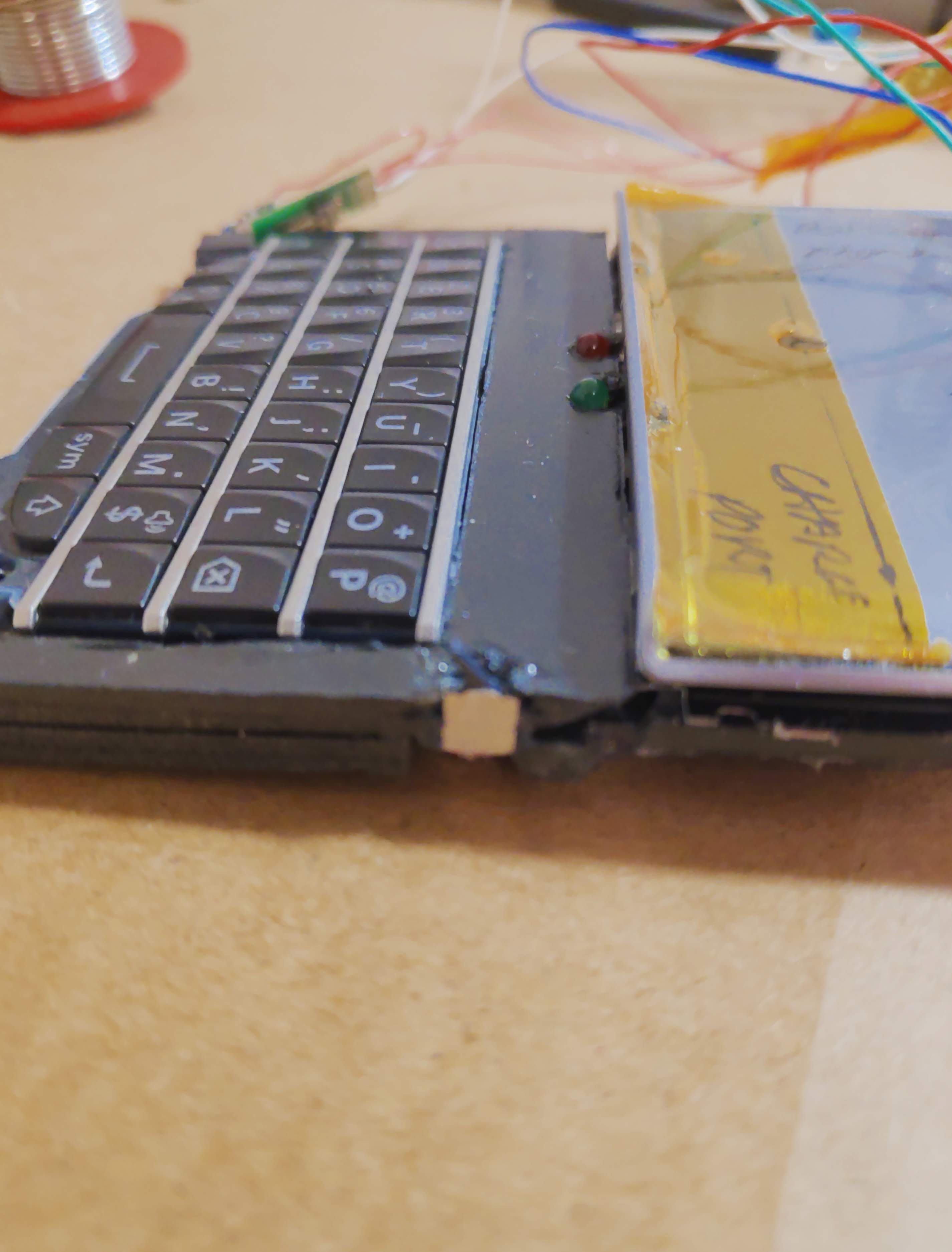
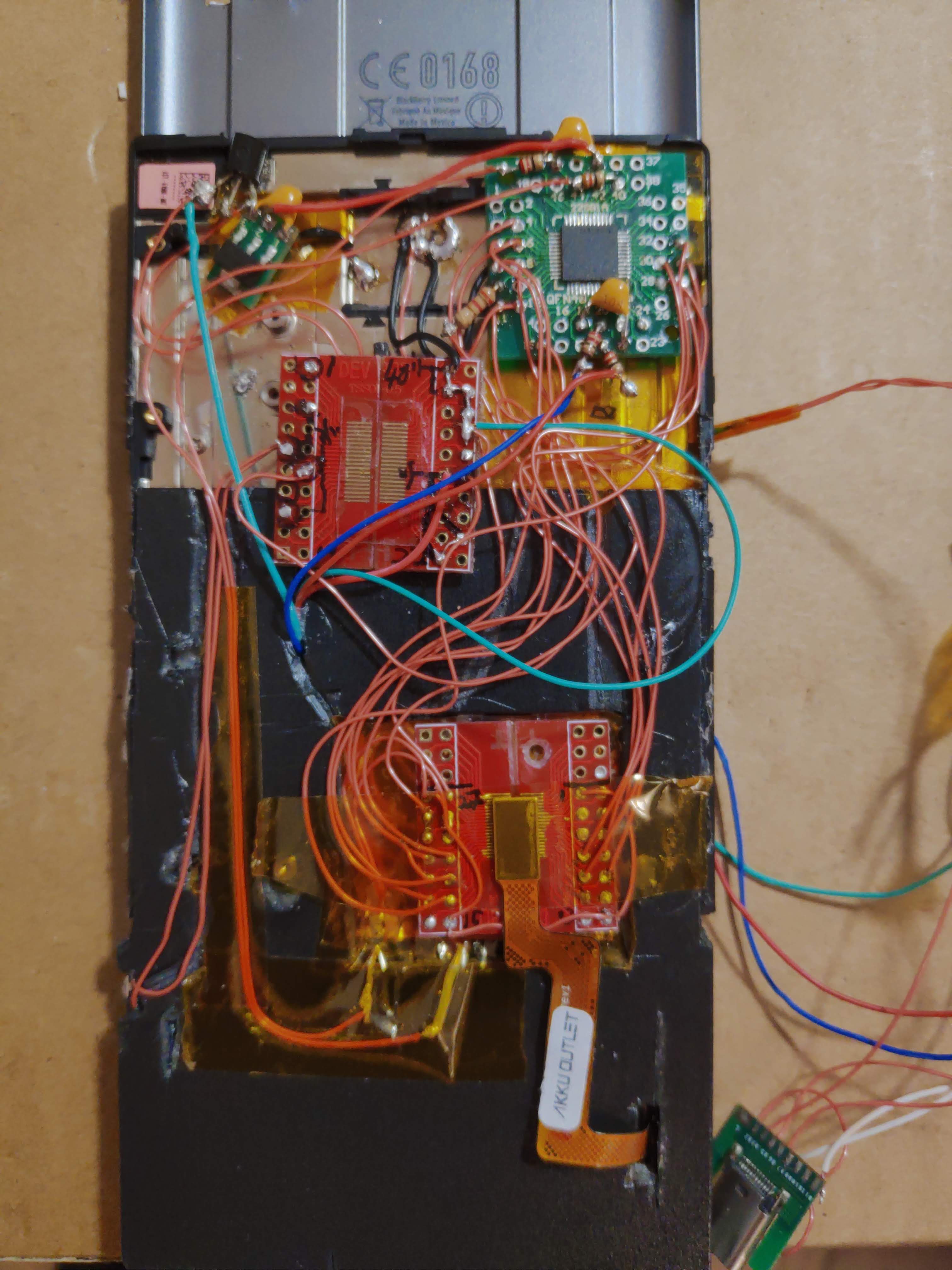
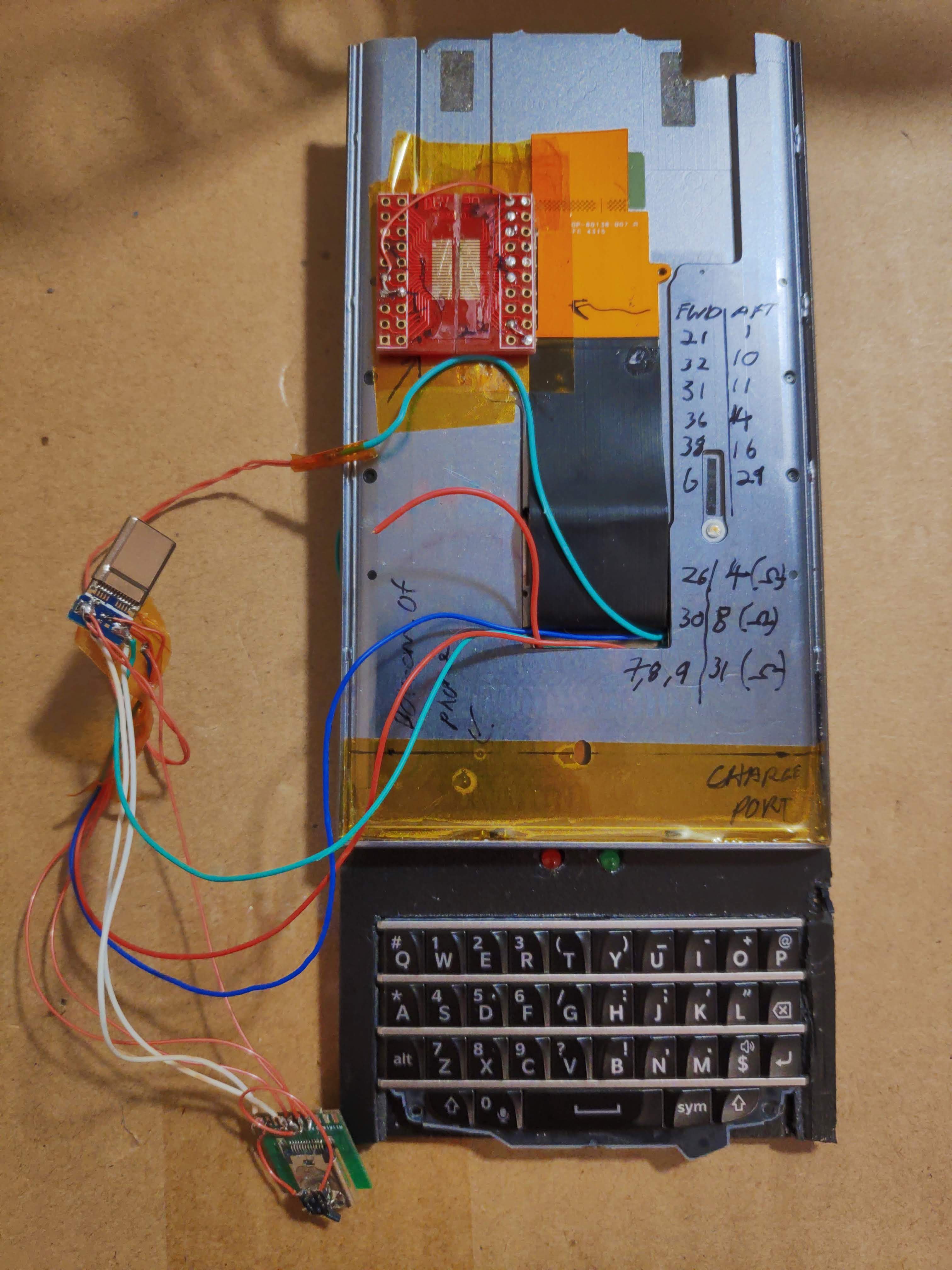
After failing to map the pinouts to the Priv's combined keyboard/trackpad, I decided to use a keyboard off a Q10, due to the decent amount of information available. Using a Hirose BM14B connector soldered onto a PCB (and this, ladies and gentlemen, turned out to be the hardest part of the whole project) I then could solder wires and map it out on a Sprintek SK5126 chip. This chip is the best one I've seen around in terms of keyboard encoders as it comes with free and easy to use software to program it, it is also designed for mobile devices and therefore inherently low-power. It can be powered directly with a 5V source (such as a phone in this case) or one can power it with a 3.3V supply.
Initially I put all components on the bare metal chassis of an old Priv, the idea was to see how all the other components would fit around it, which turned out to be unnecessarily complicated. Using a regular USB 2.0 cable, I could program the SK5126 and test out the layouts as well as hunt for shorts caused by the BM14B connector.
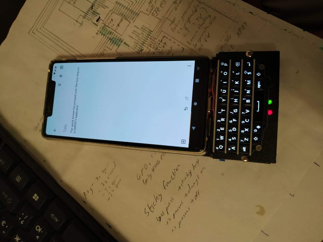
The donor phone of my choice turned out to be a Xiaomi Mi 8 SE due to its relatively high specs for its cheap price and a variety of available custom ROMs. I bought mine second-hand off ebay but for this purpose, any phone which supports OTG will do fine as Android automatically supports physical input devices OTG.
This meant I had to buy a male USB C connector and use only the Power, Ground and D+/D- lines as well as ground the Configuration channel pin through a 5.1Kohm resistor (which indicates to the phone that it is an OTG device).


 RasmusB
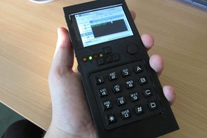
 jaromir.sukuba
 Benchoff
 Eric Woodward
Hi, nice work! However the last log update is quite updated and the BBQ20 get out in the mean time but it is not available anymore on the market. What's about developing 3rd release supporting BT/BLE with a small rechargeable Lithium battery in order to use the keyboard wireless and as a standalone gadget?