 George Gardner
Have you ever cleaned your workshop, only to find that nothing can then be found? In it's prior state, it may be messy, but you know where everything is. Unfortunately, this is the case for the buffer that is sent out via DMA.
So you have a bunch of data that you want to display on the screen. And it's in a logical order. It's likely in a format that reads left to right, top to bottom. Now, you have a crazy thing called 'DMA,' who's contantly throwing data from the buffer at the panel, in a format that the panel can understand. If we were to keep things neat, and use the logical left to right, top to bottom insertion of the data into the buffer, you'd find that your data is NOT where you want it to be on the physical screen.
You have to know how these panels are scanned. These particular panels scan from right to left 8 bits, then jump down 4 rows, scan right to left another 8 bits, filling 4 rows before returning to the top to scan another 8 bits before jumping down to the next row. I'm sure it's intelligent design for some special controller out there, but I find it obfuscated.
Rather than create logic rules to define where the appropriate pixels are to be inserted into the buffer (believe me, I did this in OpenOffice Calc, and it's not pretty) I opted to use a lookup table, or LUT. The LUT is an array of 128*64*2bytes=16,384 bytes that defines the location of the pixel in the buffer based on the address of the variable in the array.
But wait, since the scanning is the same for all panel chains (remember there are 8 sets of 2 panels chained together), we can create 1 LUT that is common for all the individual panel chains, rather than the entire display to save memory. The resulting LUT would therefore be 16*64*2 = 2Kb, where 16 is my Y axis of one set of (2) panels, 64 is my X axis of two panels side by side, and 2bytes (16-bits) are needed to store the location since the value of their locations can go over 255.
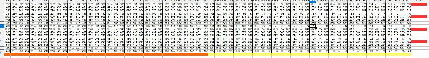
The above picture is generated via formula in Calc, in which I exported to CSV to extract the data in a format that can easily be pasted into a complier. So for instance, if you want to turn on the 3rd pixel from the top left, using the LUT array, you could get it's position in the buffer by position=pixelLUT[0][3]; This will return the value 997, where 0 represents the first row, and 3 represents the 3rd pixel from the left.
void placepixel(uint8_t xpos, uint8_t ypos, uint8_t pixeldata, _Bool gammaOn){
	if(gammaOn){
		pixeldata = gammaCorrection[pixeldata];
	}
	//what panel and pixel are we addressing?
	uint8_t ypanel = ypos / 16; //should return 0 to 3
	uint8_t xpanelpos = xpos % 64; //should return 0 to 63
	uint8_t ypanelpos = ypos % 16; //should reutrn 0 to 15

	//Determine what bit position to place the bits, this is dictated by what panel section is connected to what port # on portB
	uint8_t bittoplace = 3 - ypanel;
	if(xpos > 63) bittoplace += 4;

	//set the pixel in the buffer (0=on, 1=off)
	uint16_t bufferposition = pixelLUT[ypanelpos][xpanelpos];
	//pixeldata = ~(pixeldata);

	for(uint8_t ibcm=0;ibcm<8; ibcm++){
		panelBuffer[(bufferposition + (ibcm*1024))] |= (1<<bittoplace);			//clear the bit in position
		if(pixeldata & (1<<ibcm)){												//if the pixel needs to be on
			panelBuffer[(bufferposition + (ibcm*1024))] &= ~(1<<bittoplace);	//turn pixel on
		}
	}

}
The above is the code I use to insert pixel data inside of the free-running DMA buffer. It is a function that will take an absolute X Y value, determine what set of panels we are addressing (there are 8 sets of 2), then use the LUT, combined with the panel pair information to determine where to insert the data.
I haven't written about this yet, but the ibcm is for bit coded modulation. I'll get into that at a later date, but for the purposes of trying to understand the above code, for every bit depth of brightness on the panel, the buffer size is (128*64)/8=1024 bytes. Remember that these are not color panels, so each pixel only represents 1-bit, which is why we divide by 8.
Discussions
Become a Hackaday.io Member
Create an account to leave a comment. Already have an account? Log In.