 Maciej Witkowiak
Last time I learned that the TV part of this unit is powered by a single chip that has pretty much everything needed for audio-video decoding from RF signal integrated.
This particular device has AN5151N inside and according to several webpages all I had to do was to cut the trace with video out signal and feed external composite video signal in its place. To make it look like this:
Here is the block diagram from a helpful datasheet:
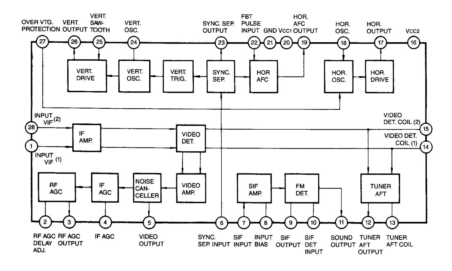
We are interested in pins: 5 - video output, 11 - audio output and 21 - ground. Browsing through forums about hacking CRT TV sets I learned a bit about various ways how they were constructed. For instance some of them had different grounds: signal ground and chasis ground. Tying external signal ground to wrong place could result in damage to one/both devices (in worst case) or degraded signal (best case).
Fortunately this modern design had external power supply or battery power options and I checked in various points that there was only one GND across whole control board.
This is the typical application cirtuit from the datasheet:
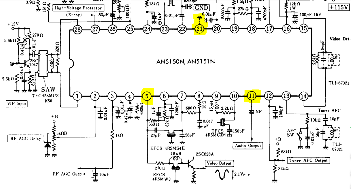
There is a common ground from pin 21. Audio from pin 11 goes through capacitor to an amplifier and speaker. Video signal from pin 5 goes through a transistor to amplify signal from 0-1V (composite) to video output feed.
I don't have schematic, nor service manual for this particular unit. I simply cut the trace near pin 5 and connected cinch socket center pin to the side of the trace that goes further into TV circuitry.
My easy way to cut the trace and not to damage anything nearby was to use a sharp pointed knife and slowly scrape a line perpendicular to the trace. Afterwards I confirmed with continuity meter that the connection was indeed cut.
Once cinch socket was connected and with an old Atari 2600 clone (with composite video mod) plugged in. I powered on the TV. I have waited several seconds for the tube to warm up and... nothing happened.
I have reconnected the signal from pin 5 and saw TV snow back, so it wasn't like I broke the device in the process.
Minutes passed while I was puzzling about it.
It turned out that while disassembling the case I turned brightness way too low to have anything visible on the (mostly dark) initial game on that console.
My advice is to be patient and turn brightness and VHOLD potentiometers very very slowly.
The next thing to do was to connect audio. I have traced the signal coming out of pin 11 and with the unit turned on I tried various places on the way of audio signal until I got good sound from the speaker. Here I didn't cut any traces because when TV is not tuned to a station the tuner is muted.
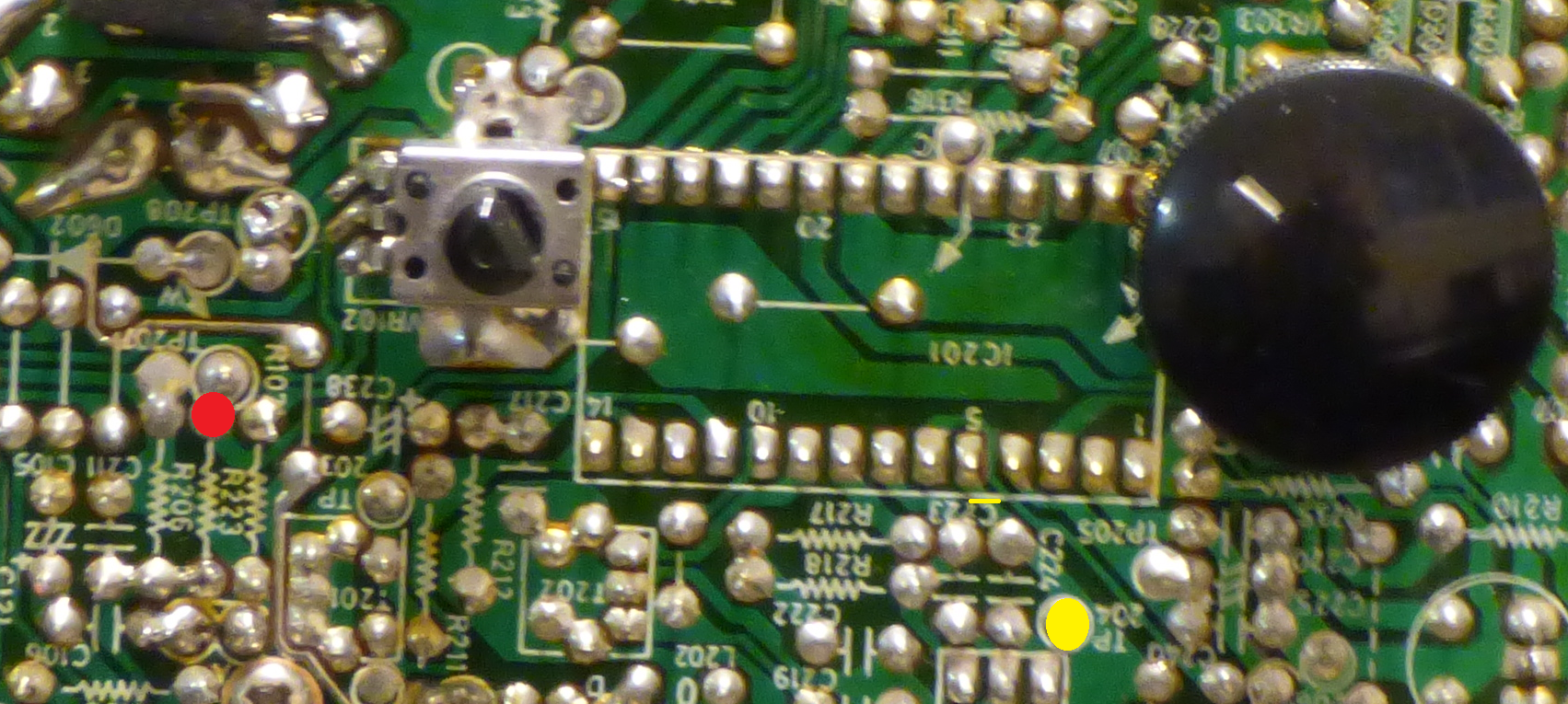
Video trace was cut on the yellow line just next to pin 5 and a new input feed was soldered to the yellow spot, a test point.
Audio signal comes through a wire soldered to the red spot.
The last thing to correct was to improve the geometry of the picture. Again, a schematic would be very helpful. I was able to find correct trimmer on the board. I could then move the picture to the right to make it more centered.
This improved the image. Unfortunately I don't see how to move it in vertical direction or how to control the width/height and correct for barrel distortion.
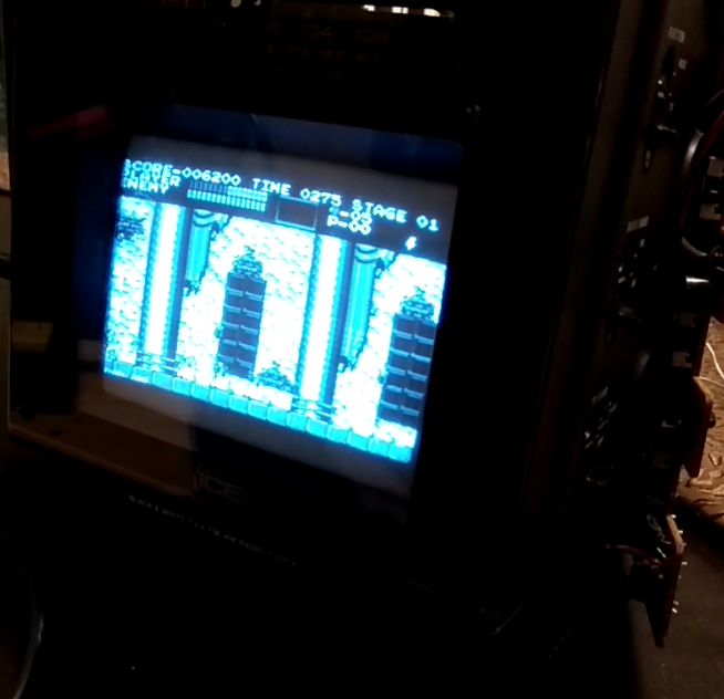
Anyway it looks gorgeous. Here is a screenshot of Castlevania from NES from an emulator running on Raspberry Pi.

More about it next time.
Discussions
Become a Hackaday.io Member
Create an account to leave a comment. Already have an account? Log In.
I got a portable TV from 1988 for free at a swap market a month ago and just finished embedding a Raspberry Pi Zero in it. Everything works great and, playing Game Boy games on a black & white screen is awesome, but I have interference problems. There's thin grey lines running across the screen horizontally and static noise from the speaker at higher volume. They only appear when there's an AV signal present. Btw, I had the same RF chip as you and I cut the trace from the video signal and audio signal. Did you isolate the chip's ground too? Thanks.
Are you sure? yes | no
I'll answer myself: I got in touch with a friend who knows electronics better and he suggested adding a 1-10uF capacitor in series on the video signal (+). I had a 0.1 uF one, adjusted the picture a little and it worked great. No more horizontal lines. Hope this can be helpful to someone.
Are you sure? yes | no
👍 I like it when electronic detective work succeeds.
Are you sure? yes | no