DIY GUY Chris
Hey guys! I Hope you already enjoyed my previous tutorial "Arduino Heart Beat With ECG Display & Sound" and you are ready for a new one, as usual I made this tutorial to guide you step by step while making this kind of super amazing low cost electronic projects which is the "NodeMCU Home automation system".
During the making of this project, we tried to make sure that this instructable will be the best guide for you in order to help you if you want to make your own Smart house, so we hope that this instructable contain the needed documents. This project is so handy to make specially after getting the customized PCB that we’ve ordered from JLCPCB to improve the appearance of our electronic device and also there is enough documents and codes in this guide to allow you create your NodeMCU project easily.
We've made this project in just 4 days only, just two days to get all the needed parts and finish the hardware making and the assemble, then we have prepared the code to suit our project and start the testing and the adjustment.
What you will learn from this Project:
- Making the right hardware selection for your project depending on its functionalities.
- Understand the Home automation systems.
- Prepare the circuit diagram to connect all the choosen components.
- Assemble all the project parts (device box and electronic assembly)..
- Start the first test and validate the project.
Step 1: What Is a Home Automation System!

A home automation system is simply a system that allows some users to have access to some electrical devices like lightning devices temperature monitoring doors control devices etc and this access is monitored through a basic application connected to the main system through a wireless or wired protocol, about the automation part, the system is able to adjust some environmental parameters automatically using some actuators and some sensors, for example the system can read temperature data from a temperature sensor and decides to turn on or to switch off an air-conditioner.

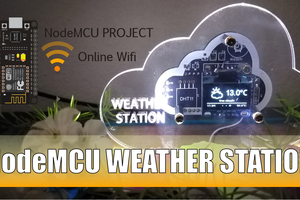
In our project we will create the main system which is an electronic circuit board based on a NodeMCU dev board which already has a wifi feature in it and this board will be surrounded by some electronic components like relays optocoplers LEDs and sensors, about the sensors we will use the motion sensor for an alarm detection, a DHT11 for temperature and humidity measuring and BH1750 for light sensing.

About the actuators, we will control some 220V AC bulbs and a DC fan and all these actuators will be controlled through an android app that we have developed through Blynk application. So in this application I inserted some gauges to read the analog values from the sensors and I placed some buttons and sliders to control my outputs.
Step 2: CAD and Hardware Parts


I used solidworks software to design this house model which already has sockets for the lightning spots the sensors and the fan, you can get the STL files from the download link down below, after preparing the design I have got my parts very well produced through a CNC laser cutting.
Step 3: Circuit Diagram

Moving to the electronics, I have created this circuit diagram that includes all the necessary parts required for this project. I am connecting the realys outputs to my NodeMCU Dev board and I use the DHT11? BH1750 and the motion sensors connected to the I²C port and to the ADC input, also I used the only PWM output of my NodeMCU Dev board and I connected it to a screw terminal in order to control the brightness of some LEDs, I used separated power supply for the relays and the NodeMCU and this way I will protect my Dev board while controlling the 220V AC voltage.
Step 4: PCB Making


About JLCPCB
JLCPCB (Shenzhen JIALICHUANG Electronic Technology Development Co., Ltd.), is the largest PCB prototype enterprise in China and a high-tech manufacturer specializing in quick...
Read more »