Close
0%
0%

SoundWing Audio I/O Board

Sound in, sound out. Now both on one FeatherWing.

Public Chat
Similar projects worth following
In from the microphone, out to the speaker... for any project that involves both microphone input and speaker output, this FeatherWing puts those two things conveniently on the same board. And if you only need one, well, at least you have that one without needing to wire up a breakout, and the other is available should your device's needs change.

That part about not having to wire up a breakout is really the inspiration for this project (and others as well). There are breakout boards for all sorts of things -- including microphone input and speaker output -- but they don't always mount neatly on the Feather system (sometimes not even the Arduino, Raspberry Pi, or other systems either, for that matter), making them a challenge to mount into a neatly-packaged final product, and often to connect as well. This is the one example that stood out to me the most, because I have a couple of larger projects in mind that would make use of it.

(Microphone and speaker not included.)

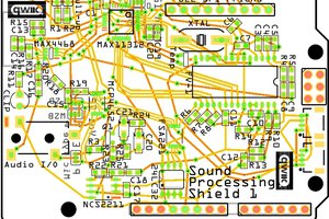
This is, essentially, two mono audio breakout boards on one FeatherWing.  The board takes audio from a microphone input and sends it the the I2C bus, then back from the I2C bus and out to a speaker. This allows the user to process the audio in various ways, depending on the needs of the application.

Thus, any of these functions (and sometimes more than one at the same time) can potentially be either turned into or integrated into a Feather project:

  • Voice changer (primarily for cosplay, Halloween costumes, and similar projects; fit the device inside a helmet, or in your pocket!)
  • Voice amplifier for teachers and other small-room speakers, actors in live theater (for smaller houses), or those with certain medical conditions (such as some forms of muscular dystrophy) that result in an unusually quiet voice
  • Electronic megaphone
  • Two-way communicator (over wires, or whatever wireless protocol you deem best -- LoRa, XBee, Bluetooth, etc.)
  • Effects processor for musical instruments (generally, but not necessarily, acoustic instruments on mikes)
  • Smart speaker (or interface with an existing smart speaker system)
  • Hearing aid (probably with some extra features that can't be found in commercial hearing aids, since those can fit inside your ear)
  • Boom mike operator's sound unit (in a film/TV setting)
  • Parabolic microphone
  • Electronic tuner/pitch pipe
  • Record/playback device
  • Myriad things I haven't thought of yet! (If you have an idea, please put it in the Comments below!)

While many of these applications involve only amplification (making the processor hardly even necessary), others involve changing the sound in some way, and/or sending it to and receiving it from another device.

Obligatory Tech Info:

The microphone input is an MAX4468 from Maxim, while the speaker output comes from an ON Semiconductor NCS2211D. Both are 8-pin SOIC chips -- a nice, compact size. In each case the application, other than connecting directly to two of the Feather's Analog pins, follows the suggested application on the respective chip's data sheet (page 9 in both cases).

The MAX4468 has a Shutdown pin which may be connected to D12. It normally is set to Low; set it to High, and the chip enters a power-saving Shutdown mode (supply current drops to 5nA, output enters a high impedance state, and bias current is switched off). In case you don't want to use it, a jumper is available to connect it to Ground full-time; it should not be left unconnected. (A jumper header is my preferred way of running an on-board selection for something that might change after installation, but not often.)

The input and output are connected to the I2C bus with an NXP Semiconductors PCF8591T/2,518 A/D and D/A Converter (a 16-pin SOIC). The default I2C address (with all three address pins connected to GND) is 1001000; the last three digits can be changed with solder jumpers. This means that one Feather can have a maximum of eight of these on board! (It's unlikely that you'll ever need more than one, but the possibility is there if I'm wrong. Besides that, there's room in any event for up to eight boards using the same or a similar I2C chip.)

Besides the Analog Reference for the PCF8591T, the only connections on the board not already mentioned are for the 3.3V and Ground.

Application:

The MAX4468 is explicitly designed for an electret microphone; I don't know for sure whether it would work with a piezoelectric mike, but I think it should. (I hope it does; one of my own designs calls for it!)

The actual connections for the mike and speaker are simple right-angle wire-to-board terminals. This is probably the cleanest solution, since the overall device will probably be kept in an enclosure that includes either mounts or jacks for these parts. You may, of course, replace them with whatever type of connector that you find appropriate (though you may need to edit the .fzz file, depending on what you choose).

Other than the mike and speaker connections, the board should be a simple...

Read more »

AudioWing 3-chip.fzz

An update of the project using a single I2C chip (and, thereby, a single I2C address). This is the version I sent to PCBWay for a prototype.

- 43.95 kB - 01/09/2020 at 23:30

Download

AudioWing Semi-Final.fzz

An improved layout for the earlier I2C-capable version (which is now deleted). I'm holding on to this one in case the 3-chip version sucks.

- 46.59 kB - 12/07/2019 at 17:22

Download

  • 1 × Printed circuit board from the Fritzing file provided
  • 1 × Maxim MAX4468 Microphone Preamplifier IC; substitute the (pin-compatible) MAX4467 if desired
  • 3 × 10kΩ resistor
  • 2 × 2kΩ resistor
  • 4 × 1µF ceramic capacitor

View all 17 components

  • Sound Processing Shield

    bobgreenwade08/18/2020 at 14:09 0 comments

    The replacement project for this is under way here.

  • Moving to a Shield

    bobgreenwade06/10/2020 at 15:05 2 comments

    After much struggling and researching, I've been unable to figure out how to use I2S as a bidirectional multi-slave bus for audio. Maybe it can be done, and maybe it can't; I'm just not able to figure it out.

    I've thus decided to set this project aside and turn my attention to an Arduino Shield that combines this with the EchoWing. That will bypass the need for I2S, taking the processor out of the audio flow altogether and leaving it to control the effects and other functions.

    I'll supply a link in a separate log here once I've started that project here on Hackaday.

  • I2S, Not I2C; and, Bad Blocks

    bobgreenwade05/07/2020 at 16:14 0 comments

    I've become aware of two major problems with my current design, one fundamental and one simple hardware.

    The fundamental one first: as you've probably gathered from the title, I'll be switching the I/O protocol from I2C to I2S. I'd been under the impression that the I2S-related pins on Feather boards weren't broken out, and only learned in yesterday's Hackchat that it is possible to attach I2S to a Feather (as some people clearly have done). I'm still trying to figure out which pins to use, as help in that regard is fairly sparse, but once I figure it out I'll be switching not only this board but also the two other audio-related Feathers (the TunerWing and the EchoWing).

    The other problem is with the connector blocks for IN and OUT. It turns out that the footprints for the TE Connectivity ones I'd chosen are, relative to the board itself, huge -- and of course they don't fit the spots that I'd set aside for them. I'm going to switch to something else -- probably Molex, though I'm still wishing to put something there that can accommodate bare wires.

    On a related note, I'm switching to Kicad. Once I worked out how to install a Template for FeatherWing, I found it fairly easy to use -- not much harder than Fritzing -- and quite flexible. The files I'll be uploading in the future will be from Kicad, replacing the Fritzing ones I've been using.

  • I Screwed Up

    bobgreenwade03/30/2020 at 17:41 0 comments

    I just got word that my PCB layout is all wrong: the MAX4468 and PCF8591T are the wrong size. So, I'm going to have to call the PCBs already printed up a loss, and get new ones done.

    Thankfully, Riley at PCBWay is very helpful and will walk me through the process.

    I'll change the files here (the JPG and the FZZ) once I've finalized what I'm sending (probably later today).

  • It's on its way!

    bobgreenwade03/05/2020 at 15:54 0 comments

    I just put in the order for the prototype for this board. With all costs, coupons, etc., the total price is $60; for a single, fully-assembled prototype (with four board-only siblings) coming from China, I don't think that price is too bad.

    The bad news is that the coronavirus outbreak has caused some delays, as the production facility had to be shut down for a couple of weeks. The lead time was already kind of long (about a month, if memory serves), but I won't be expecting this until around mid-May.

    I'm not too worried about that, though, since I still have to get other parts and stuff in order to test this board, and that'll take about that long. So, it all works out!

  • One's all I need for prototyping

    bobgreenwade02/09/2020 at 19:47 0 comments

    After working with Riley, my assigned customer service representative at PCBWay, I've reduced the number of assembled boards in my order from 5 to 1. This saves quite a bit off the bill; the tag is now $62. That seems like a steep price for a Feather-sized PCB, but given that it's a single prototype (and I still get 4 boards without the parts), that's not too bad. I can let out a more formal run, with a lower cost per assembled board, once I'm sure it works correctly.

    Between my own finances and delays at PCBWay because of the coronavirus outbreak, I'm waiting until at least 5 March to actually pay for and order the board.

    (As a side note, while I'm not clear on whether Riley is male or female, this individual is really incredibly helpful and dedicated to doing a good job. That's something I've noted with Chinese companies in general, and I've been told is simply a part of Chinese culture. Many of my fellow Americans could learn a thing or three from them in this regard. I'm not always happy with the product itself, but customer service is top-notch.)

  • Price Estimate: That's More Like It

    bobgreenwade01/14/2020 at 16:34 0 comments

    I just got the estimate from PCBway for the new configuration: $95 for five boards. That's $19 each, which is not a bad price at all.

    I don't think I'll be needing any more revisions; I just need to wait to find out what happens with the contest, and for my bank account to have that much space in it. If I end up buying them myself, it'll probably be at least February 5, and possibly as late as March or April.

    (I may be wasting money by buying assembly for five boards. PCBway only makes boards in lots of 5, or I'd get just one or two. I may revise my order and get only one assembled, especially if I have to revise the board design.)

  • Now Do 2 Pull-Ups

    bobgreenwade01/12/2020 at 19:17 0 comments

    Note to self: Always double-check the pull-up resistors for the I2C bus.

    (I inadvertently deleted them when I cleared out the two separate I2C chips to replace them with just one. It's fixed now.)

  • 100kHz or 400kHz?

    bobgreenwade01/12/2020 at 00:36 0 comments

    Working out some details, I noticed that the PCF8591T only works at the 100kHz speed on the I2C bus, and I'm not sure how well audio will transmit both ways well through the bus at that speed (especially since the device I'll mainly be using this for also uses an EchoWing, which also drives audio along the I2C bus both directions, making four signals along that bus). I took a look around for something that could go on the 400kHz speed, and found the Analog Devices AD5593R will do that.

    The bad news is that the AD5593R has many bells and whistles (it's an 8-channel configurable chip, with each channel configurable to ADC, DAC, or GPIO) that I won't use, but that drive the price up another $2-3. Given that I'm trying to keep the price down, I think I'll hold off on that configuration, unless someone advises otherwise.

    (I did put together the layout, though, so it'll be ready just in case.)

  • The 3-chip Approach

    bobgreenwade01/09/2020 at 23:43 0 comments

    After the price shock I got this morning, I went on a more dedicated search for a less expensive, single-chip option for an ADC/DAC. I think I found one, with the NXP Semiconductor PCF8591T. It has four analog inputs, but it's not a problem to just tie the extra three to Ground; the $2-3 price tag also makes the board much, much less expensive, as well as much more open in terms of space.

    I'm going to just hold on to this for a while before I send another quote request to PCBWay. Just from that one change, I do think I'll end up saving about $25 from that $138. I probably can also eliminate a few other components; I'll have to study the data sheets a bit more than I have. With any luck, I'll be able to bring the total with them to under $100 (meaning less than $20 per board).

    Barring some calamity, I hopefully will have something truly presentable by the time a decision is made on the Take Flight With Feather contest (this is the version I'm now promoting for it -- unless, of course, it's too late to do something like that).

View all 24 project logs

Enjoy this project?

Share

Discussions

Similar Projects

Does this project spark your interest?

Become a member to follow this project and never miss any updates