Close
0%
0%

Viam Sonus 2.0

An audio router board with integrated volume control and buffered output

Similar projects worth following
12x8 audio router based on the ADG2128 analog crosspoint switch, the DS1881E for volume control, and the LME49726 as output buffers.

Features:

  • 12 input channels that are arbitrarily routable to any of 8 output channels.
  • Onboard digital potentiometers on the input side with non-volatile storage. Pots are logarithmic with zero-cross detection, and are paired in order with their input numbers on the board's silkscreen.
  • Onboard op-amps on the output side with 300mA drive capability to provide buffering for direct-drive of line-level signals.
  • Onboard buffered voltage divider with exposed output and 300mA drive capability to aid design and implementation of input buffers.
  • Resistors added to the input-side of the switch, but after the potentiometers to allow for simple resistance mixing of signals simply by routing two inputs to a given output without risking damage. Some caveats apply (discussed below).
  • Input-side is left free-form to allow use with single-ended (unbalanced) or differential (balanced) signals, and/or DC-biased sources.
  • Safe for 5v audio signals.
  • Isolated analog and digital power planes.
  • Silkscreen reflects the envisioned usage (stereo signals), but the driver allows for easy grouping of any number of channels.
  • Breadboard-friendly

Specs and requirements:

ParameterMinimumMaximumRecommended
Digital voltage range2.7v5.5v3v - 5v
Analog voltage range4.5v5.5v5v
Channel current1mA
Current requirements (Digital)<5mA
Current requirement (Analog) Note 0  1mA2.7A


Notes:

  • 0: Analog current requirement depends strongly on draw from outputs and VccDiv/2 pin. Figures given are total board ranges.

Full documentation can be found here.

  • 1 × ADG2128 Switches and Multiplexers / Analog Switches and Multiplexers
  • 6 × DS1881 Data Converters / Digital Potentiometers
  • 5 × LME49726 Amplifier and Linear ICs / Operational Amplifiers

  • Boards with new silk are ready

    J. Ian Lindsay12/12/2019 at 23:03 0 comments

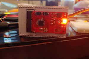
    After some hangups with USPS, the new boards are finally built and assembled as of last night. Photos updated to reflect reality.

    The value of a stencil

    With as many fine pads as this board has, the first few units took me about 1.5 hours each to assemble. Of that, most of the time was spent painting solder paste onto pads. I ordered a stencil for this one, and measured assembly time last night. 

    Linear time costs (paid once per board with or without stencil):

    • 10 minutes to place parts under the microscope
    • 1 minute to bake and cool
    • 1 minute to inspect soldered board
    • 1 minute to clean the board after soldering
    • 1 minute to test on debug jig

    The step costs that differ with a stencil are...

    • 2 minutes for jig setup with a blank board, stencil aligned and clipped into place
    • 3 minutes to spread the paste
    • 1 minute to remove the board and inspect the paste application

    Constant time costs (paid once for each assembly session):

    • 2 minutes to setup
    • 8 minutes to dispense the needed parts from stock
    • 2 minutes to clean up

    Lesson learned: I figure the stencil saves about 130 minutes per board, and gives far cleaner results, besides. Highly recommended, even for assembly of one unit of this pad count.

  • Updates

    J. Ian Lindsay12/05/2019 at 23:13 0 comments

    Hardware restock date

    The first batch of boards will arrive on Saturday, the 7th. I will build and test them that night, and they should be reflected as stock on Tindie by Sunday night. Since the BOM cost on these is about $50, I'm only building three of them this run. If those fly off the shelf, I'll adjust my build rate until I match demand (which I have no idea about, at present). Just know that I pay attention to waitlists. So if I'm ever out of stock on anything, and you add yourself to the waitlist, I will typically have you served within 3-weeks at the outside. Sometimes faster.

    Basic and TRS connector boards

    I've spent some cycles applying the knowledge gained from my testing efforts into making certain the reference schematics are safe and clean. This is finished (on paper), so you can now build off the schematic yourselves. But I have yet to roll the boards. Once they check out, I will list them on Tindie. The first two boards will be basic versions with no digital elements. One of the two will have power and TRS jacks and a high-wattage regulator. The other will be much cheaper and have IDC headers for connector breakouts. Both will be for single-ended signals.

    Documentation and bug fixes

    Lots of small bug fixes and improvements have been bleeding into the DS1881 and ADG2128 drivers over the past few days. So re-pull those at the same time you re-pull the Viam Sonus repo. All the READMEs have been updated with discourse on driver features.

    Upcoming software features

    The advanced sketch demonstrating mixing and advanced configuration topics will likely be the next major software feature to be released. The hardest part of getting it done is defining a sensible API. The rudiments of this are checked in to the repo, but none of it is in use yet. SoonHorse.jpg

  • More driver improvements

    J. Ian Lindsay11/30/2019 at 22:31 0 comments

    The drivers had a tremendous amount of technical debt cleared away last night. Bus references are no longer hard-coded to "Wire", but are instead passed in as an argument to init(), and is then retained by classes that need it. This costs an extra 30 bytes of resting memory load for ViamSonus, but paves the way for the linux TwoWire abstraction, and makes life generally easier for anyone using the board with (suppose) "Wire1".

    Additionally, every driver in the glueball (the driver for the DS1881, and the ADG2128), and the glueball itself now support state serialization and restore. It needs some more testing, but it should allow state restore before or after init(), allowing for "profiles" and easy management of preferred settings, default states, etc. Buffers written this way are versioned so that new driver features can be gracefully migrated in. Those APIs are essentially finished, so they are now safe to code against. All of the example sketches are updated, tested, committed, and pushed.

    Unrelated to the above feature is another feature that is important for the linux port: preserve-on-destroy. When the driver instance for the switch is destroyed, the default behavior is to put the hardware into a known state (reset). This opens all routes. Use-cases that want the hardware state to outlive the driver's life cycle are now possible again.

    Lots of sloppy private boolean class variables were condensed into something more efficient and manageable (int member with flags).

    Next Steps:

    The ViamSonus driver is about to undergo mitosis into four separate classes to fully separate concerns and make the API stable and sensible to use.

    • The driver itself
    • InputGroup
    • OutputGroup
    • A class for running scheduled operations

    The linux TwoWire and GPIO abstractions are all that stand in the path of linux SBC support. The Makefile and example program are committed, but won't compile until those issues are resolved.

    Hardware availability projections

    Once I get the boards from OSHPark, I will assemble them that night. I should have 3 tested units available for sale, and at a lower price (so hold tight for the price cut). If those disappear quickly, I'll restock at about 3 weeks out.

  • Steady progress

    J. Ian Lindsay11/27/2019 at 09:33 0 comments

    Something happened at OSHPark that I've not seen ever in the 6 years or so I've been using them. A QC failure notice (fab's fault). No big deal. They'll re-run the boards. But it will be delayed a bit longer. 

    The example i/o schematic was changed slightly to reflect a configuration with far better low-end response.

    Added the Makefile for linux support program, but the i2c abstraction isn't in place yet for the dependencies.

  • Documentation on mixing capability

    J. Ian Lindsay11/25/2019 at 00:49 0 comments

    I took some time writing documentation for the hardware, and improving the software. Driver doesn't yet deal with mixing yet, but the hardware doc is finished.

  • Arduino driver compiles again

    J. Ian Lindsay11/24/2019 at 09:29 0 comments

    A bit of porting effort today, and the ViamSonus class once again compiles under Teensyduino. Example sketch isn't fleshed out yet, and the driver's correct operation isn't yet tested.

    The ViamSonus class is a glueball around one instance of the ADG2128 and six DS1881E potentiometers. In the last version, part of that glue's responsibility was to ensure there were no input collisions (which the ADG2128 driver will happily allow). Now the glue should allow mixing.

    Also, I've published an example input biasing schematic. Please don't use it until I've run it through more paces. The wipers on the volume control are fairly wimpy, and I want to make certain I can't burn them with a hot signal.

  • Board checks out

    J. Ian Lindsay11/19/2019 at 05:45 0 comments

    First unit tests good. The switch is at address 0x70 and the POTs are 0x28-0x2D.

            Ping Map
                  0 1 2 3 4 5 6 7 8 9 A B C D E F
            0x00:   . . . . . . . . . . . . . . .
            0x10: . . . . . . . . . * . . . . * .
            0x20: . . . . . . . . * * * * * * . .
            0x30: . . . . . . . . . . . . . . . .
            0x40: * . . . . . . . . . . . . . . .
            0x50: . . . * . . . . . . . . . . . .
            0x60: . . . . . . . . . . . * . . . .
            0x70: * . . . . . * * . . . . . . . .
    

    Published schematics.

    The previous version of this board has a library that worked well, and included an abstraction layer for i2c on Arduino and Linux (for use with an SBC). I'd like to port those features over, but the main library effort is for Arduino right now. The drivers for the elements of this board are both ready, but the class that ties them together is what adds many of the worthwhile features.

    I've sent off for a revised board with better silkscreens. Any orders will receive the new boards.

    Immediate software goals (in order of urgency):

    • Finish porting of AudioRouter class.
    • Finishing basic example sketch to fully demonstrate board.
    • Finishing sketch to demonstrate audio ducking and cross-fade
    • Porting linux console example program

    Hardware surrounding this board might include (in no particular order):

    • 1/8" simple jack board with input buffers and no digital elements
    • 1/8" complex jack board with input buffers and monitoring ADCs on the input side
    • A Teensy adapter board
    • A modular analog synth backplane 
    • Differential adapter boards

View all 7 project logs

Enjoy this project?

Share

Discussions

Similar Projects

Does this project spark your interest?

Become a member to follow this project and never miss any updates