 shane.snipe
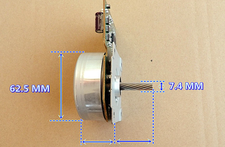
I have always wanted to use the box of motors I had left over from the lead free transition to make some robots. The motors were the DD6450 motors and they 30W 24 V motors that spun at 2850 RPM. I had found some rubber rings that fit well over the motors and turned the outer rotors into wheels. The on board drivers made this motor pretty easy to drive with an Arduino but I wanted to be able to control it with my cellphone so we had a bit of 3.3V output from the ESP32 to 5V input problem. Here is the basic pinout:
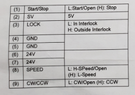
So 24V runs directly from the battery so that is not an issue. Pins 1,2 and 8 work with 3.3V inputs. Pin 3 keeps the circuit running while not powering the motor. Maybe it is good for fast starts but I have not been using it.
The pin that has been a thorn in my side is Pin 9 CW/CCW. For some reason the 3.3V pin can not drive it. It actually does not run when attached to a ESP32. So to get around this sticky problem, I added a L293D motor driver. I use the 3.3V to switch the 12 or 16V coming in. I then drop it through a 5V regulator to drive the motor pin.
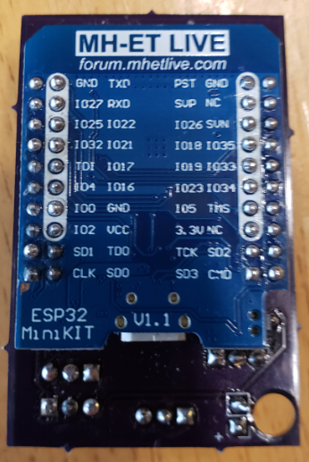
I wanted to make this controller as compact as possible, both to make it easy to mount and to save the cost of making the pcb. I used the MH-ET ESP32 shown below.
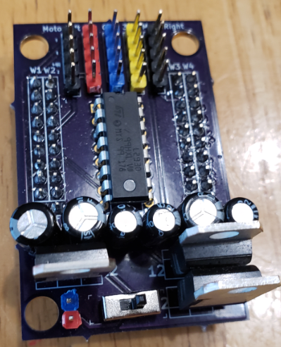
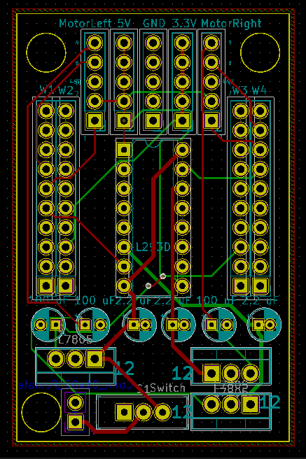
On the top side board I mounted the motor controllers, linear regulators and output pins. The ESP and the logic to drive the motors do not take much power so I did not attach the heat sinks to the back plane.
Full disclosure, this is a mechanical engineer making one of his first boards. It is functional but I can imagine I broke a hundred laws of elegant circuit design in making this happen. If anyone wants to school me in the comments, I am all ears. I probably would start with the power and ground inputs right next to the mounting holes in the bottom left corner above. I guess I am using nylon mounting screws!
Here is the top of the board. This is actually a big step for me. Being a MechE I generally do not believe in capacitors but I put to see if it helps out at all. On other projects with this motor I have had some intermittent operation where touching the circuit made it work. It could have been a bad solder joint but after hearing of the story from Jeri Ellsworth on how the China fab team removed the capacitors and made her C-One project not work. She put her hand on it, changed the capacitance and figured out that she did not make a dud of an ASIC. In the abundance of caution, I added capacitors to this board. Lots of them!
Outside of this board, the robot will only need a terminal strip to attach the 12V-16V. I am leaning towards 4 x 18650s just because I do not have a battery holder for 3. I want to get the BMS going but the first round will charge outside of the robot.
So from the top, the pinout is:
5) CW/CCW -- Pin 9 on the motor. This is boosted to 16V through the driver and then dropped to 5V. Pin 34 for the left motor and Pin 32 for the right motor direction.
4) Speed -- Next pin down is pin 8 on the motor, and 35 for the left motor and 27 for the right motor. There is a high and a low speed and low will probably be good for most driving.
3) Ground -- Pin 5 on the motor. Pin 4 will go to the ground on the power strip.
2) 5V -- This is Pin 2 on the motor. I believe this is what powers the electronics. My hope is that if this is off, the 24V wired directly from the batteries will not be drawing any current.
1) Start Stop - This should work as an enable, disable. It is pin 33 for the left motor and pin 25 for the right motor. Pulsing it may provide some crude PWM and make it somewhat possible to run this robot indoors.
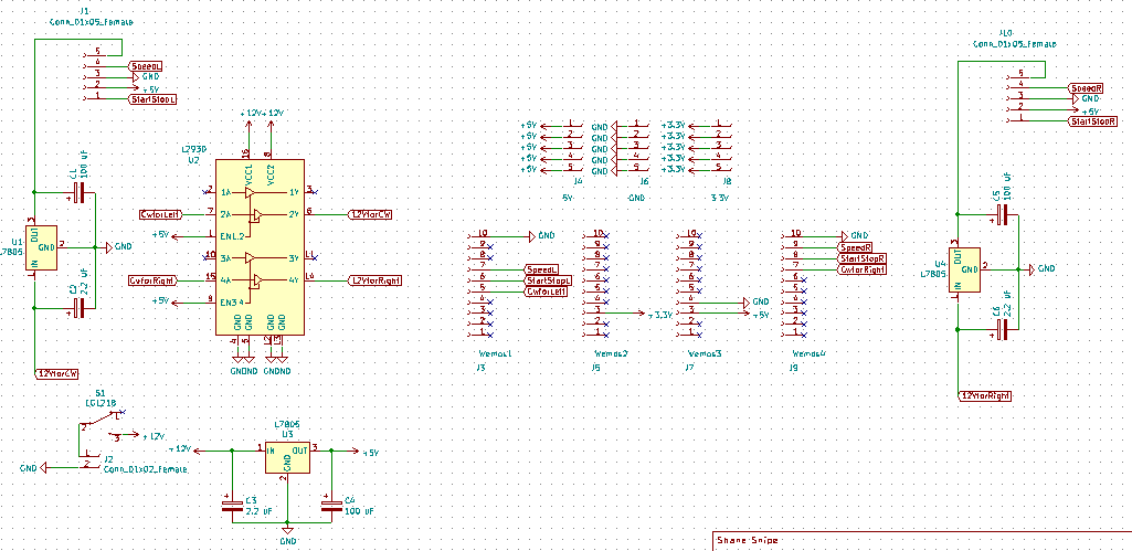
For completion here is the Kicad board
I am not sure if anyone can find similar motors but if they are available, here is the board.
As a testament that you really can find anything on the internet, I actually found this motor being sold as surplus on Ali.
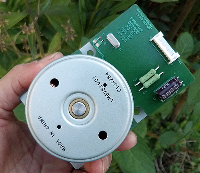
The connector shown in the picture is a PH 2.0 9 position. I really struggled with connections until I found this one. Here is a link.
And that is about as far as I have gotten on the electronics for this project. I will provide a programming update soon.
Discussions
Become a Hackaday.io Member
Create an account to leave a comment. Already have an account? Log In.
have 4 same motors scrapped from Kyocera printers
thx for board!
Are you sure? yes | no