Close
0%
0%

USB-C Power Delivery Sink - CYPD3177

A USB-C PD Sink up to 20V 5A based on the Cypress CYPD3177 USB PD Controller

Similar projects worth following
This is a USB PD Sink Trigger / Decoy board. Rev 5 now available. Another improvement with TVS protection diodes on input and output and new FETs as power switches. The new FETs have a Rds_on of only 6.9 mOhm (measured), which reduces the dissipation even more compared to the previous version even with 5 A current draw.
What is it?

USB-C PD offers the option to negotiate power delivery from a compatible power supply. The USB-C PD-Sink plays the role of a sink device, enabling any device to be powered from a USB-PB power supply. Any type of power connector can be attached through a 2-pin screw terminal or directly soldered into the PCB for a lower profile. The voltage can be set to 5V, 9V, 15V (12V with solder bridge), or 20V and the current can be set to 1A, 2A, 3A, or 5A. This board has new FETs, which have a Rds_on of only 6.9 mOhm measured. Also new in this latest revision are 2 TVS diodes on the input and output for over voltage and surge protection.

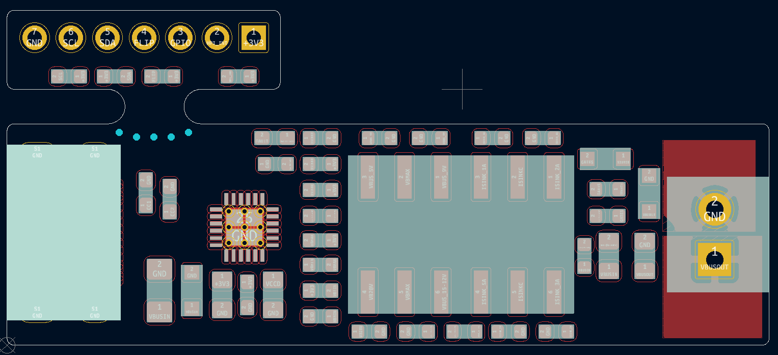
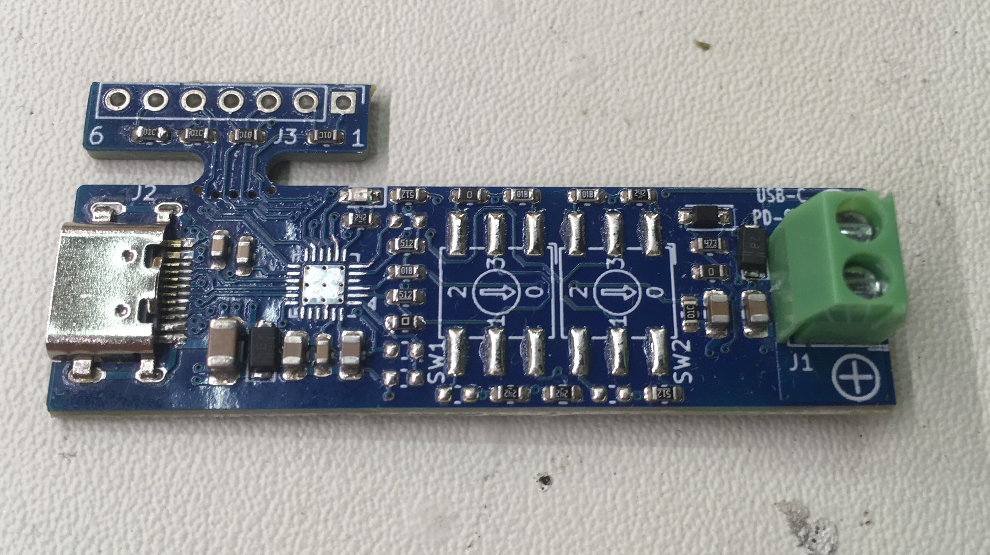
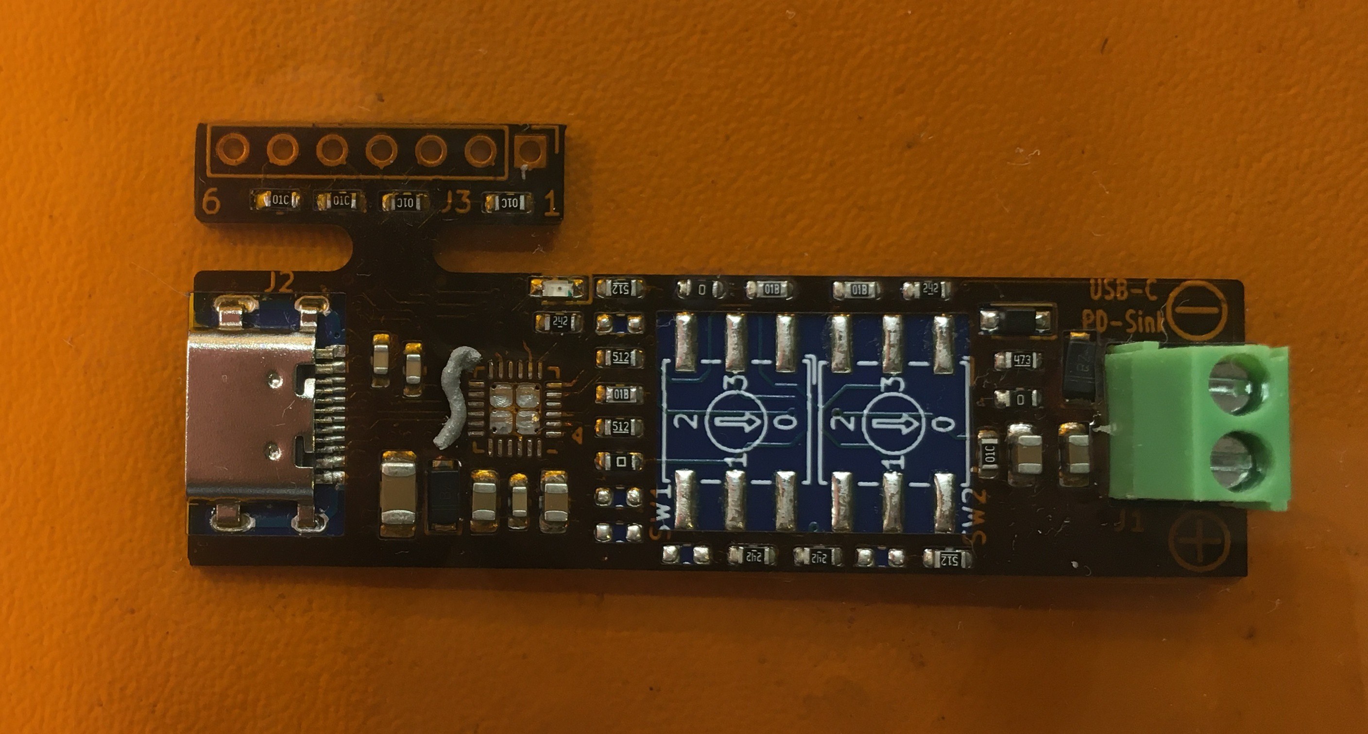
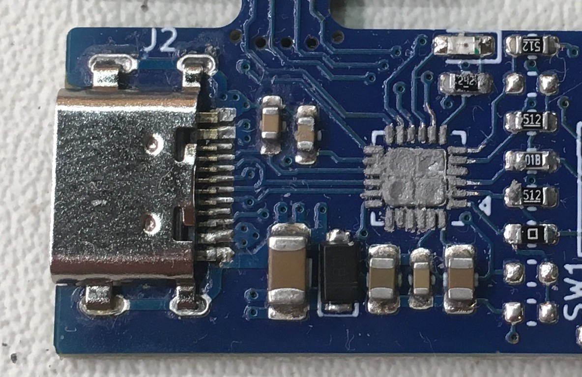
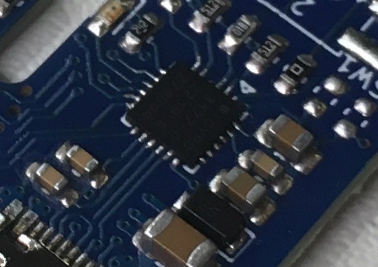
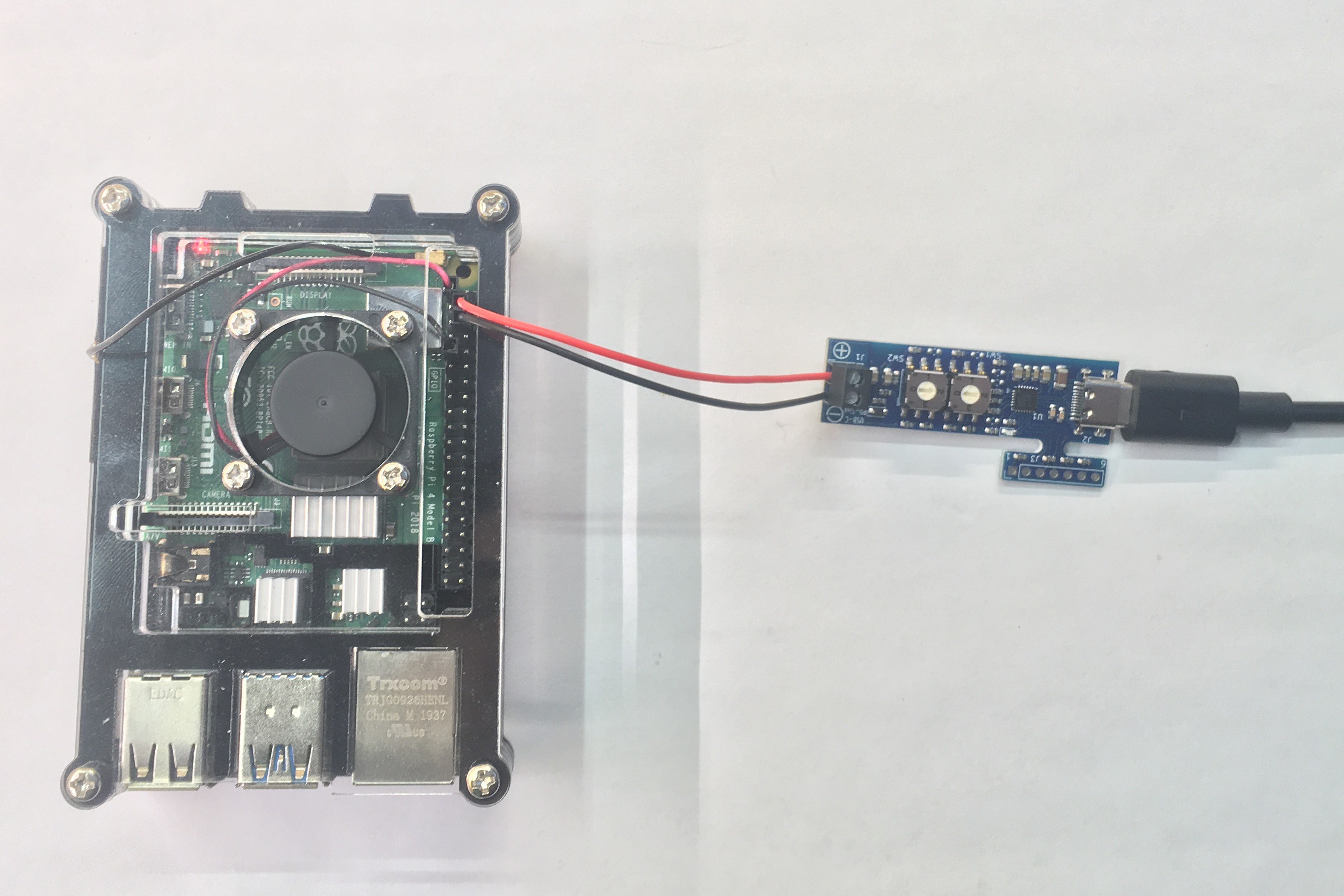
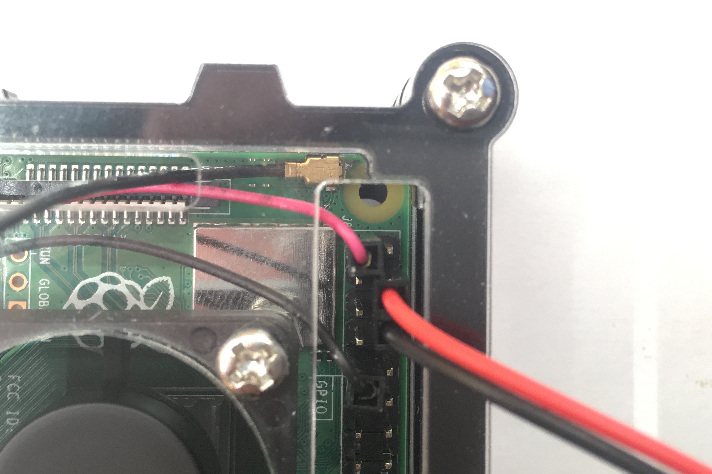
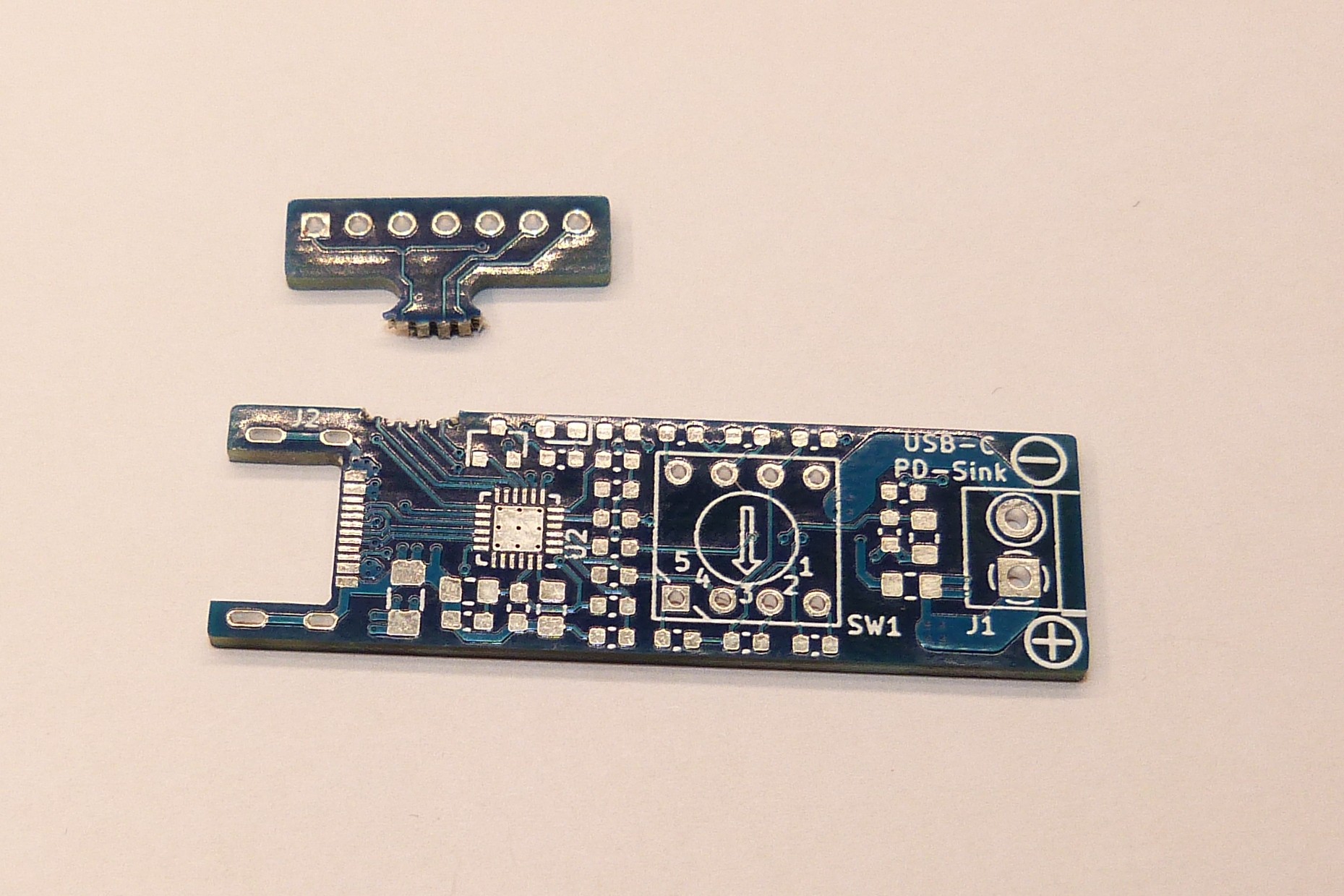
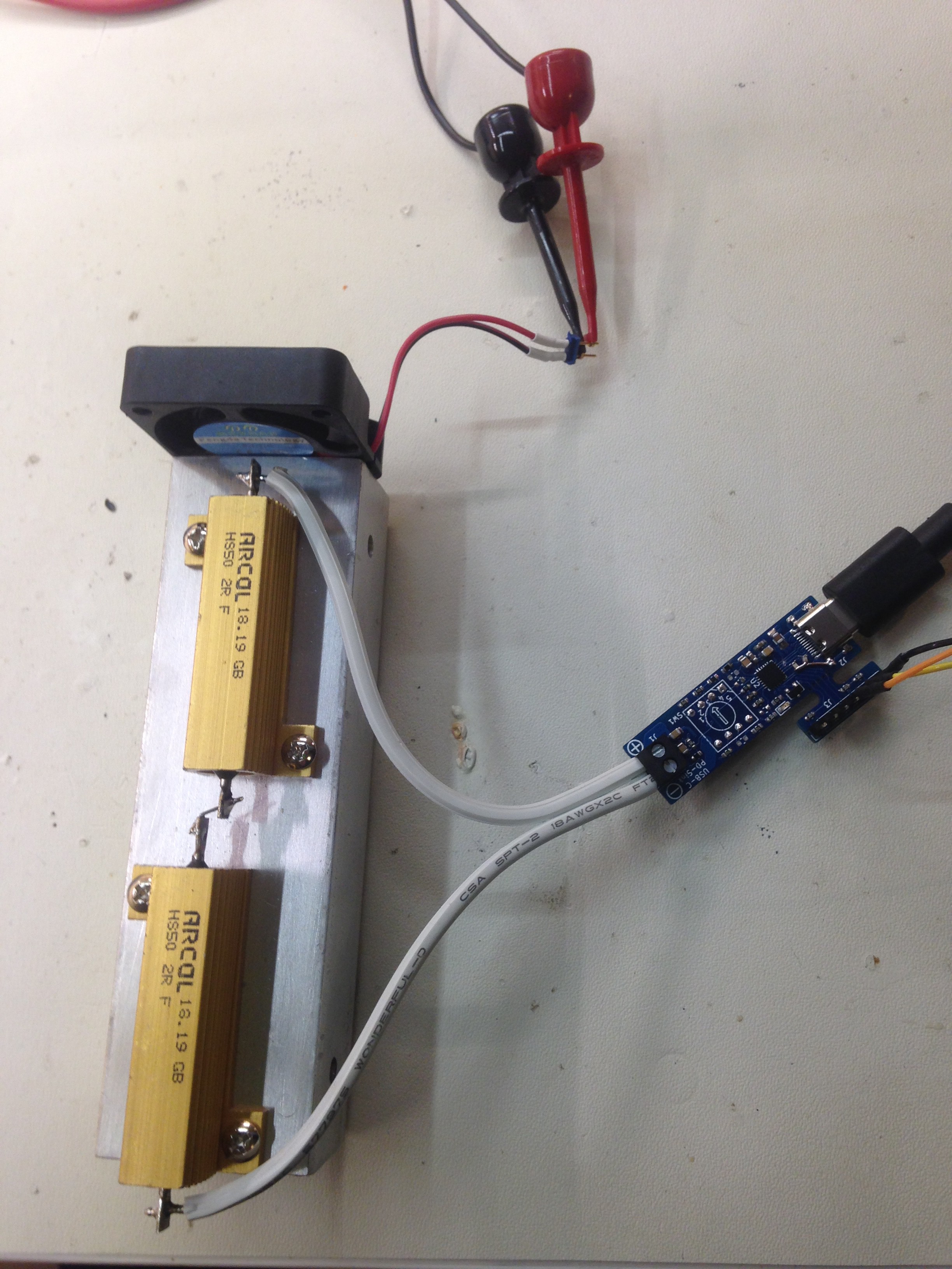
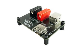
This board has the goal to replace random power adapters with a standardized way to use a USB-C power delivery (USB PD) adapter instead. For regular operation, no programming or software configuration is involved with this design. All options are set through the switches or resistor values. If needed an I2C interface to a microcontroller is available, to access status and control registers. This part of the board is separated through a break-off tab (mouse bites) and can be snapped off. I made the conscious design decision to not add a USB-A connector option at the output end. I did not want to build a device, that is capable of putting more than 5V on the VBUS pin of a regular USB cable and potentially destroy the device that is plugged in. A heatshrink tube can protect the board in a permanent installation.

This is a set and forget device. Set your current and voltage needs before plugging the device to your USB-PD source and enjoy the power at the output. This is not a power supply to change voltage and current during operation.

All Features:

  • USB-C PD Power Delivery PD Sink Decoy / Trigger
  • Selector switch S1 for 5V, 9V, 15V (12V with solder bridge), or 20V
  • Selector switch S2 for 1A, 2A, 3A, or 5A
  • Max current 5A, settable in 250mA steps through resistor options
  • Red LED to indicate failed power request
  • I2C telemetry interface to controller chip
  • Snap off option for telemetry interface
  • For fixed voltage, the switch can be replaced by wire jumper
  • Small form factor to be heat shrinked as part of the power cable
  • Size 53mm x 15.4mm (without telemetry interface)
  • Height 12mm with screw terminal and switch, 6mm without.
  • 3" (7.5cm) heatshrink tube for protected installation
  • 2oz copper to safely handle 5A
  • Lead free assembly

AD USBC-Sink_ver5 back.pdf

Assembly Drawing Bottom Side Rev5

Adobe Portable Document Format - 29.25 kB - 04/24/2022 at 02:05

Preview
Download

AD USBC-Sink_ver5.pdf

Assembly Drawing Rev5

Adobe Portable Document Format - 42.03 kB - 04/24/2022 at 02:04

Preview
Download

SC USBC-Sink_ver5.pdf

Schematic Rev5

Adobe Portable Document Format - 76.43 kB - 04/24/2022 at 02:04

Preview
Download

SC USBC-Sink_ver4.pdf

Schematic Rev4

Adobe Portable Document Format - 75.89 kB - 08/13/2020 at 02:02

Preview
Download

SC USBC-Sink_ver3.pdf

Schematic Rev3

Adobe Portable Document Format - 72.18 kB - 08/13/2020 at 02:03

Preview
Download

View all 10 files

  • 1 × Cypress CYPD3177 USB-C Pwer delivery Controller QFN-24
  • 2 × Nidec Copal CS-7-14 5 pos rotary switch TH
  • 1 × METZ CONNECT 31060102 2pin screw terminal 2.54mm LCSC PN C123214
  • 1 × Jing Extension C168688 USB-C plug mid mount LCSC PN C168688
  • 2 × Diodes DNP3013 Single P-FET 30V 9.5mOhm DFN-8

View all 10 components

  • Selective Stencil Soldering

    MagicWolfi08/12/2022 at 01:32 0 comments

    Just like everybody else, the chip shortage has caught up to me sooner or later. The controller chip CYPD3177 for my USB-C Power delivery (PD) sink was out of stock everywhere for several months. So I decided to order boards populated with everything except the chip (and some of them also without the switches as they were short on stock as well). Sometimes the quick turn assembly houses only stencils solder paste onto the pads of the populated components, no matter what the provided Gerber paste layer looks like. With this in mind I tried to come up with a new (for me) method to apply paste for re-flowing the chip.

    When the IC was available again I bought enough to finish all the boards and put them in stock in my Tindie store.

    Enter the "selective solder stencil". I created a new paste layer and left only the chip pattern as intended to have the pin pads and the bottom center pad open. For all other components I created openings as big as the perimeter of component body+ solder pads. This enables the stencil to slide over already populated components and as a nice side effect being perfectly centered over the empty footprint. I ordered the stencil from OshStencils, as Polyimide film. A thin strip of cut credit card served as paste squeegee to spread the paste only in the desired area. Lifting the stencil left the paste in the correct place. The distribution was not perfect due to the fact that the polyimide stencil was not perfectly flat but bowing up a little. But during re-flow/hot air soldering, the solder usually knows where to go to build nice solder joints and no bridges.

    For this try I used hot air for soldering as the screw terminal would not be happy about excessive time on the hot plate. Everything went smooth and the board worked perfectly as expected.

    This exercise remained a proof of concept, as the board house was so kind to also put solder on the un-populated pads, which made the whole process easier. Putting down some sticky flux was enough to activate the existing solder and connect the chip just as good as with fresh paste. Next time I would make the opening maybe 1 or 2 mil (25 um or 50 um) wider to give some tolerance to the whole process.

    Here are some pictures to demonstrate the steps from empty board to finished assembly:

    This is how the KiCAD design looks like; light blue is the selective solder stencil layer with the red pads shining through.

     
    The partly assembled board with a clean footprint for the chip to be populated

    The orange stencil placed over the board. The already assembled components are sticking nicely through the openings. A somewhat enough amount of paste is ready to be spread over the footprint. 


    Solder is squeezed into the stencil openings.

    The pasted board without the stencil ready to have the chip placed onto the pads.

    And the finished board:

  • USB-C Power Delivery for every RPi

    MagicWolfi03/07/2021 at 01:46 0 comments

    With the USB-C PD Sink board, it is possible to power every RPi (except the RPi 400) with a USB PD power supply. The board is set to 5V (switch S1 on pos 0) and 3A (switch S2 on pos 2) and connected to the RPi 40 pin HAT connector through a 2-pin header. On this header pin 4 for +5V and pin 6 for ground is used. 


    A detail picture of the connector. The red and black wire to the right are the power supply. For reference, the red and black to the left are the fan of the enclosure.


    And for more reference, here is a generic HAT header pinout (courtesy RPi foundation website).


    A word of caution: connecting power to the wrong pins or having the PD board set to a voltage higher than 5V will cause permanent damage to the RPi. Only try this at home when you know what you are doing. And then do it right. Check and check again, and check on more time.

    And don't mind the UMC connection on the RPi, that is a story for a different time.

  • Selecting the right FET

    MagicWolfi11/08/2020 at 02:34 0 comments

    Selecting the right FETs as the power switch is important, when switching 5A at 20V.

    My initial pick was the Alpha & Omega AON7407. It has very good Rds_on but was lacking at V_drain-source with only -20V max and V_gate-source of only 8V. Better candidates turned out to be:

    Diodes DMP3013 with V_ds = -30V and V_gs = 25V; Rds_on 9.5mOhm (V_gs=10V)

    Rohm RQ3E120    with V_ds = -30V and V_gs = 20V; Rds_on 8.8mOhm (V_gs=10V)


    The following scope plots all show:

    Ch1: signal GATES

    Ch2: signal VBUSIN

    Ch3: signal SOURCE

    Ch4: signal VBUSOUT

    Math: Ch3 - Ch4 = SOURCE - VBUSOUT to measure Vds

    The 1st step to 5V is the initial USB power up, the trigger point is the successful power contract negotiation (blue,light blue and purple trace rise to 20V) and~140msec later, the FETs finally turn on(green trace starts raising) and the input voltage drops slightly because of the 4.85A current draw.

    Q1, Q2 = AON7407:

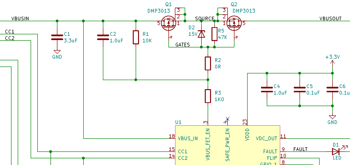
    Q1, Q2 = AON7407 with D2 = 7.5V Zener Diode:
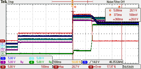
    Q1, Q2 = Diodes DMP3013:
    Q1,Q2 = Rohm RQ3E120:
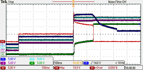
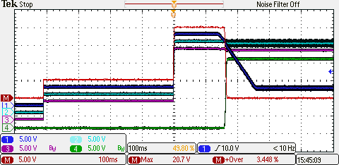
    The AON7404 shows a weird pulse on the math channel when USB-VBUS turns on to 20V and the turn on cycle with 15V gate voltage is not really smooth.
    The Diodes and Rohm FETs behave identical with proper turn on cycles.

    In the end I decided to use the Diodes DMP3013, as it has extra gate protection diodes built in.

  • Power FET Diodes DMP3013

    MagicWolfi10/28/2020 at 01:13 0 comments

    And then I found an even better FETs that has a Rds_on of only 9.5 mOhm (at Vsg = 10V), which is just as good as the previous one as Vsg >10 V at the output setting of 12V or more.

    This FET is the Diodes DMP3013SFV. same 3.3mm x 3.3mm footprint.

    And I did a measurement with 19 boards, which showed to real Rds_on to be 7.3 mOhm onaverage, because the Vsg is ~15V at the 20V setting. Also the calculated junction temperature is quite low and much more manageable now.

    Results (still fixed width font anybody?):

    Vfet*2    Vload    I load    P load    P fet    Tjunc    Rds on
    70.5       19.47       4.87      94.77      0.343    46.4    0.0072
    71.04      19.61       4.90      96.14       0.348    46.8    0.0072
    70.7        19.62      4.91       96.24     0.347    46.7    0.0072
    72.8       19.59      4.90      95.94     0.357    47.3    0.0074
    70.6       19.64      4.91       96.43      0.347    46.7    0.0072
    72.4       19.64      4.91       96.43      0.355    47.2    0.0074
    71           19.66      4.92      96.63      0.349    46.8    0.0072
    69.4       19.67      4.92      96.73      0.341     46.3    0.0071
    72.8       19.63      4.91       96.33      0.357    47.3    0.0074
    73.1        19.62      4.91       96.24      0.359    47.4    0.0075
    71.4        19.61       4.90      96.14       0.350    46.9    0.0073
    69.9       19.63      4.91       96.33      0.343    46.4    0.0071
    72.9       19.64      4.91       96.43      0.358    47.4    0.0074
    70.8       19.62      4.91       96.24      0.347    46.7    0.0072
    71.3        19.64      4.91       96.43      0.350    46.9    0.0073
    73.6       19.6        4.90      96.04      0.361     47.5    0.0075
    72.3       19.61       4.90      96.14       0.354    47.2    0.0074
    71.9        19.61       4.90      96.14       0.352    47.0    0.0073
    74.7        19.64      4.91       96.43      0.367    47.9    0.0076
                                                   ...

    Read more »

  • New FETs with lower Rds_on

    MagicWolfi08/17/2020 at 02:18 0 comments

     Time passes...

    I finished the design of Rev4 (and Rev3 in between). Most important improvement is a 2nd switch to select the current and new switching FETs . The new FETs have a Rds_on of only 9.5 mOhm (at Vsg = 4.5V), which cuts the dissipation almost in half and keeps the board cooler, even with 5 A current draw.

    This FET is the AON7407.

    And I did a measurement with 24 boards, which showed to real Rds_on to be 7.1mOhm onaverage, because the Vsg is ~15V at the 20V setting. Also the calculated junction temperature is quite low and much more manageable now.

    Results (fixed width font anybody?):

    Vfet*2    Vload    I load    P load    P fet    Tjunc    Rds on
    73.3        19.55    4.89    95.55    0.358    47.4    0.0075
    72.5        19.58    4.90    95.84    0.355    47.2    0.0074
    70.2        19.6      4.90    96.04    0.344    46.5    0.0072
    69.3       19.6      4.90    96.04    0.340    46.2    0.0071
    71.2         19.55    4.89    95.55    0.348    46.7    0.0073
    68.6        19.65    4.91     96.53    0.337    46.1     0.0070
    71.2         19.59    4.90    95.94    0.349    46.8    0.0073
    68.1         19.68    4.92    96.83    0.335    45.9    0.0069
    69.7        19.67    4.92     96.73    0.343    46.4     0.0071
    68.5        19.67    4.92    96.73    0.337    46.1      0.0070
    68.4       19.7      4.93     97.02    0.337    46.1      0.0069
    68.7        19.7       4.93    97.02    0.338    46.1      0.0070
    72.8        19.69    4.92    96.92    0.358    47.4    0.0074
    69.5       19.71     4.93     97.12     0.342    46.4    0.0071
    70.6       19.71     4.93     97.12     0.348    46.7     0.0072
    68.3       19.72    4.93     97.22    0.337    46.0    0.0069
    68.4       19.71     4.93     97.12     0.337    46.1      0.0069
    70.7        19.71     4.93     97.12      0.348    46.8    0.0072
    71.1          19.7      4.93     97.02     0.350    46.9    0.0072
    68.4       19.7      4.93     97.02     0.337    ...

    Read more »

  • Production

    MagicWolfi02/17/2020 at 12:31 1 comment

    Production at home for the next batch went very well but slow. How I have to set up a larger supply chain.

    OCD anybody :)

  • Break off tabs

    MagicWolfi02/02/2020 at 01:06 0 comments

    The break-off tab for the telemetry connector seems to be working as planned. I tested it with a bare board and it snapped right off. For a populated board I would recommend to score a line along the holes on both sides first to put a little less stress on the components nearby.

  • The heat is on.

    MagicWolfi12/18/2019 at 02:03 0 comments

    I have built a load to test the power draw of the board. It is 2x 2Ohm 50W resistors in series. This gives me a current draw of 5A at 20V. Cooling is not adequate yet, with 3.66A @ 14.6V the heatsink gets up to 92degC, with 3A @ 12V I am measuring 72degC. The fan cannot keep up with 5A @ 20V, the temperature rises to over 100degC in less than 2 minutes.


    I need a bigger heat sink.

  • HPI telemetry

    MagicWolfi12/15/2019 at 18:05 0 comments

    I managed to talk to the BCR over the I2C interface, which is not quite straight forward, as the chip adds a mandatory 3 to5 cycle clock stretch. My solution so far is a bus pirate set to I2C 5 kHz clock speed. With those commands I am able to read out ID and status registers, even though the response does not match the datasheet for the IDs.

    [0x10 0x00 0x00[0x11r]
    [0x10 0x02 0x00[0x11rr]
    [0x10 0x0D 0x10[0x11r]
    [0x10 0x08 0x10[0x11r:4]
    

    No luck using an Arduino Due ( which has 3.3V IOs) so far. :(

  • FET power dissipation

    MagicWolfi12/13/2019 at 18:38 0 comments

    The switching FET in this circuit has to carry up to 5A, which is significant. Thus the drain source resistance Rds-on is important to be minimized and power dissipation through the package needs to be calculated. Here are some test results, in the form of voltage drop over the dual DS junctions.

    U load [V] I load [A]V drain-source x2 [mV]Tjunction [degC]P diss [mW]Rdson [mOhm]
    5.071.2756.529.572
    22
    9.032.26  
    61.633.7139
    14
    11.983.00
    89.541.8268
    15
    14.623.66
    106.549.3389
    15
    19.674.92
    141.068.3693
    14

View all 14 project logs

Enjoy this project?

Share

Discussions

thommo17 wrote 06/14/2021 at 06:50 point

Hi Wolfgang,

I just found your project whilst looking for a way to power my device with USB C.

I was hoping you might be able to help me find some information on how to make one myself but have it permanently set as 5V 3A as I will only need a max of 15W.

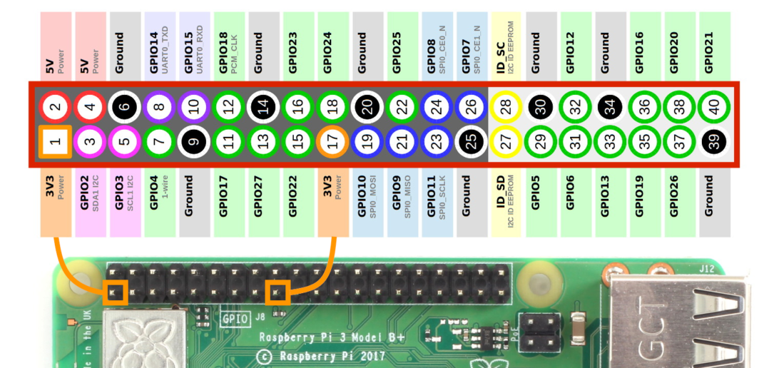
I'm quite the noob when it comes to electronics though so I am not sure what I am looking at when I look into your schematic.

Thanks!

  Are you sure? yes | no

MagicWolfi wrote 06/16/2021 at 02:09 point

Hello there,

This is what you need to implement:

How to connect a FT232RL to a USB type C connector - Projects - KiCad.info  Forums

[Image right by KiCAD.info Forum]

Ignore D+,D- if you don't need USB data transfer.

This should tell every USB-C power supply to source 5V 3A if it is capable to do so.

My schematic uses the CYPD3177 USB-C power delivery sink controller, which is only needed for voltages >5V.

  Are you sure? yes | no

thommo17 wrote 06/16/2021 at 03:54 point

Awesome! Thanks for that. I've just put it together. Hopefully my math is correct and it's enough power. 

Would you recommend any other protections to put in place?

  Are you sure? yes | no

MagicWolfi wrote 06/17/2021 at 02:36 point

Sorry I can't reply to your last comment. Other protection: you might want to consider a TVS diode on VBUS to protect your 5V circuit against bursts of overvoltage or static events. 

  Are you sure? yes | no

thommo17 wrote 06/17/2021 at 08:05 point

Cool. I'll have a look to see what suites best for my circuit and add one in. Maybe I'll use a fuse somewhere too just in case. 

It'll be good to learn about them all as I find the right one to put in. All the schematics for components are like another language to me right now. 

  Are you sure? yes | no

red wrote 06/10/2021 at 16:29 point

Hello,

This is very nice!

I am redesigning it in a simpler way: only one 15V/3A contract, with two straps on PCB to exceptionally draw 20V/5A (With Apple PowerBook PS). I have designed same gizmo with STUSB4500, but unfortunately it ran out of stock worldwide until end of this year... unless you're ready to spend 20$/piece on AliBaba!

I understand you are trying to keep the BOM low priced, but you might consider IRF9310 as a  good PFet option, or even SiRA99DP (expensive one).

Theres's one thing bothering me, though: USB-C PD  requires a discharge path (usally a NFet inside the chip itself) on DC out when switching to a lower voltage PDO...  CYPD3177 doesn't provide such a discharge path.

Best regards.
Matt

  Are you sure? yes | no

MagicWolfi wrote 06/12/2021 at 01:01 point

Hello Matt,

Thanks for answering to the comments that I had missed in the last months. :) Much appreciated. The FETs look interesting, especially the R_ds_on and the thermal performance. Package size might be a challenge to fit and still have enough space for thick enough trace for the current load.

I am not sure, if the USB-C PD sink is required to have a discharge path. I know the source needs to have one and all PD source chips I have seen do so.

And there is a discharge resistor between VBUS and SAVE_PWR_EN (5V only) to bring VBUS down to a safe level if the 5V fallback is enabled.

Best regards, - Wolfgang.

  Are you sure? yes | no

Jaron West wrote 04/27/2021 at 20:08 point

Great project and really helpful for understanding the functionality of USB-C PD without added complexity of programming. I'm curious looking at the rev 4 schematics why the ISNK_FINE is pulled down by 5.1K resistor (R14) rather than 0 as suggested in cypress documentation when using DNP on the pull-up?

  Are you sure? yes | no

red wrote 06/11/2021 at 10:08 point

Hello Jaron,

CYPD3177 sets voltage and current contracts by reading (ADCs) the voltage window on the deicated pins (see table 2 of DS). If you want to save board space and lower the BOM, tie the pins to ground. If you have room and can afford an extra resistor, that leaves open possibilities for PDOs in the future : Do Not Populate the Pull-up, and even with 5.1k instead of 0 Ohm for Pull-down, you still get 0V on pin V_BUS_MIN (pin 1).

Regards.
Matt.

  Are you sure? yes | no

MagicWolfi wrote 06/12/2021 at 00:36 point

Hello Jaron,

Sorry, I missed your post, as below I did not get a notification.

Again, Matt answered your questions (Thanks, Matt!). Also, if I wanted to set a fine current, with a 0 Ohm resistor I would need to change the resistor and add another one. With the 5.1K resistor I have at least the chance to set a fine current of 750mA with only one additional component.

Cheers,

 - Wolfgang.

  Are you sure? yes | no

Gray Olson wrote 04/15/2021 at 04:54 point

Any chance you have advice on sourcing CYPD3177's? They're sold out for several months at all the major distributors 😓

  Are you sure? yes | no

red wrote 06/10/2021 at 16:29 point

Hello Gray,

Looks like it's on stock (again?) at Digikey.

Cheers.

Matt

  Are you sure? yes | no

MagicWolfi wrote 06/12/2021 at 00:29 point

Hello Gray,

Sorry, I missed your post, the notifications seem to be broken.

What Matt said is correct.

Cheers, Wolfgang.

  Are you sure? yes | no

Tim Rightnour wrote 01/19/2021 at 19:09 point

I'm working on a project where I need 5v and 12v output from a power supply.  My thought was to use one of the meanwell dual/triple output ones, but could this do it?  Would I in theory use two of these?

  Are you sure? yes | no

MagicWolfi wrote 01/20/2021 at 12:10 point

You would need 2 USB-C PD power bricks and connect the grounds of the PD Sink boards together. To be on the safe side, the 2 power bricks should be plugged into the same power bar.

  Are you sure? yes | no

Pal-Kristian Engstad wrote 09/10/2020 at 18:19 point

Hi, 

According to the data sheet, D+ and D- should be left unconnected. 

P

  Are you sure? yes | no

MagicWolfi wrote 09/11/2020 at 01:08 point

Hi Pal-Kristian, I was in contact with Cypress about that. Their answer was: "D+/D- connection is for Apple charging 2.4A, USB BC 1.2. If you do not want these legacy charge features, you can left it unconnected." 

 - W.

  Are you sure? yes | no

Jim Taylor wrote 09/09/2020 at 20:30 point

Hello,

  I am working on making some Power Supplies for my desk, I would like to have one with three USB-C PD ports, and am planning to use a 24V Meanwell power supply to accomplish this.  I know I can tune it down to 20V +/- for the output of the power supply.

  This device looks like what I am aiming for in plugging that 20V into the back and then allowing whatever I plug in to handshake and request it's appropriate voltage (be it a laptop or my TS-80 and it will receive the correct voltage.  Am I reading this correctly?

  Sorry for the newb sort of question but I am still learning and extremely interested in USB-C and the possibilities it opens up for power and data transfer.

  Thank you!

   James

  Are you sure? yes | no

MagicWolfi wrote 09/11/2020 at 00:57 point

Hello James, my device does the opposite from what you need. It is a USB-C PD sink. It can only negotiate a certain voltage/current from a PD source. You can only connect a load to what you are referring to as the back of my device and not feed power into it from this side. Hope that helps. - Wolfgang.

  Are you sure? yes | no

Aidan Chandra wrote 07/20/2020 at 01:20 point

Hi! I'm planning on using this in a project needing simple USB C Charging. I've just got a few questions.

1. On the datasheet, page 8 Table 4, the fine adjust resistors adjust +250A, is this a typo and is it for mA?

2. What does the FAULT pin do if it cannot negotiate the desired current?

3. The FAULT pin is only active when there is no voltage within the given range? What if the device can source 9V2A and 12V1.5A and I set the min current to 2A - will it give me 9V2A and not throw a fault?

Thank you so much in advance. This chip, and specifically, your schematic, have saved me WEEKS of dev time.

  Are you sure? yes | no

MagicWolfi wrote 07/27/2020 at 17:01 point

Hello Aidan,

Sorry for the late reply, somehow I did not get a reminder note of new comments. :( I am glad my work is helpful for you. 

1. Yes, mA is correct. 

2. The fault pin goes to logic HIGH if the requested current cannot be supplied by the power source. 

3. I would guess, it would negotiate 9V 2A because that setting can satisfy the request, but I am going to try to test that later today. 

Cheers,

 - W.

  Are you sure? yes | no

Aidan Chandra wrote 07/27/2020 at 21:44 point

No Worries!

Thanks so much for the help. I'll be ordering my own PCBs soon with this chip in conjunction with a MAX 3S Lipo Charging IC. I will keep you abreast to how it works out.

  Are you sure? yes | no

MagicWolfi wrote 08/06/2020 at 02:01 point

To your question 3: I would negotiate 9V2A. As an example I have a power bank that can do 12V/1.5A or 9V/2A or 5V/3A. I have set my PD Sink to request Vmax=20V Vmin=5V and I=2A. The set voltage is 9V and I could draw up to 2A and not set fault pin.

  Are you sure? yes | no

Charles Yarnold wrote 07/01/2020 at 12:00 point

Just to check, if you set it to say 12v and the controller can only supply up to 9v, will you get 9v or nothing out of the screw terminals?

I'm hoping the answer is nothing as the draw back to the similar tools on Ali is that the setting will mean "up to and including but not over the set voltage", but that's not useful if you want to power something that needs _only_ 12v!

  Are you sure? yes | no

MagicWolfi wrote 07/03/2020 at 00:57 point

The controller has a min and max voltage. If the power supply can support anything in the requested range, it will output its max available.

If you set the min and max to 12V on the controller, it will not output 9V if this is the maximum, but turn on the fault LED. It is a very flexible device, it does what you tell it to do. The boards I am selling on Tindie have a minimum setting of 5V, but can be changed with a single resistor.

  Are you sure? yes | no

Charles Yarnold wrote 07/03/2020 at 10:20 point

Wonderful, thanks for clarifying!

  Are you sure? yes | no

patrick wrote 01/22/2020 at 10:24 point

Hi,

I just came across these. though they don't provide all voltages, they are a lot smaller. I can't say anything about the quality though. do you have any insight in where your solution trumps this?

https://nl.aliexpress.com/item/4000459863567.html?spm=a2g0s.9042311.0.0.617e4c4d3s6ccU

Patrick

  Are you sure? yes | no

MagicWolfi wrote 01/22/2020 at 17:49 point

Hi Patrick,

the risk tip list is very interesting in this regard.

My board does not output any other voltage than the requested one. The Ali board sounds very random here. 

The Ali board cannot request a specific current. So if the power supply cannot supply enough current for your load what is going to happen?

My board does have a telemetry interface for control and status.

How about a polarity marked connector for your back end cable. 

I am using 2oz copper thickness for better current capacity.

My board comes with support.

You have to know very well what you are doing or feel very lucky with the Ali board :). I don't know how they do it, but I can barely source the chip for that price. My board will be an order of magnitude more expensive :(

 - W (sigh). 

  Are you sure? yes | no

patrick wrote 01/22/2020 at 18:19 point

Fully understood and clear answer! Obviously this can not be compared, but it's interesting developments. For testing and safe working I am still awaiting the next steps in this project 😉

  Are you sure? yes | no

Peter Senna Tschudin wrote 01/12/2020 at 20:16 point

Are you planning to sell it too? I'm definitively interested in buying a few.

  Are you sure? yes | no

MagicWolfi wrote 01/22/2020 at 17:50 point

Hello Peter,

Sorry I just saw your post. 

Yes, I am planning to sell them very soon. I have PCBs at home, just need some time for assembly and documentation before I put them up on Tindie. Stay tuned.

 - W.

  Are you sure? yes | no

MagicWolfi wrote 02/01/2020 at 02:12 point

Hello again Peter,

The board is up for sale on Tindie now.

https://www.tindie.com/products/pier42/usb-c-pd-sink/

  Are you sure? yes | no

patrick wrote 12/10/2019 at 14:56 point

Great. 

If it is resistor value based and the voltages are set, that also means no programming need to set it up?

Looking forwards to it! what is you expected planning?

  Are you sure? yes | no

MagicWolfi wrote 12/11/2019 at 00:53 point

Exactly, this is what I love about this chipset. No programming involved. AWESOME.

And now the pressure is on, to commit to a schedule. If all testing goes well and I don't do any stupid mistakes on the next rev of the layout, I might have hand-assembled units end of January.

  Are you sure? yes | no

MagicWolfi wrote 01/31/2020 at 19:36 point

Hi Patrick,

Just wanted to let you know that the board is now up for sale on Tindie (and it is still end of Jan, YAY). I like the whooshing sound of deadlines rushing by. 

  Are you sure? yes | no

patrick wrote 02/17/2020 at 18:06 point

ordered!

  Are you sure? yes | no

patrick wrote 12/09/2019 at 22:45 point

Hi very interesting project and definitely following this! would be interested to buy a couple if they are as affordable as they look ;-)

would it be possible to re-program the voltages to different V/A combinations?

Patrick

  Are you sure? yes | no

MagicWolfi wrote 12/09/2019 at 23:57 point

Hello Patrick,

Thanks for your interest. Yes, the plan is to sell them once everything is working, pricing is not fixed yet.

The voltage settings are limited to 5V, 9V, 12V, 15V or 20V. Current settings are very flexible in steps of 250mA from 0 to 5A, but it depends also on the source, if it can limit the current in those small steps. All settings are through resistor values on the board.

 - W.

  Are you sure? yes | no

Similar Projects

Does this project spark your interest?

Become a member to follow this project and never miss any updates