Close
0%
0%

HP 11947A clone

A refresh of the HP 11947A attenuator and limiter

Similar projects worth following
The HP 11947A is a 10 dB attenuator and transient limiter that operates from 9 kHz - 200 MHz. The transient limiter protects RF test equipment against power levels that might otherwise damage their sensitive front end. It also incorporates a 6 kHz high-pass filter. It's obsolete but the schematic and original layout are available so I decided to make a clone, and shrink the design using surface mount parts. I also tweaked a few of the resistor values to be closer to ideal resistive pad numbers and the result is the "11947B".

The parts list for the 11947A is in its manual and finding replacement SMD passives was easy. The V1 "SURGE PROTECTOR 90V" part, based on its shape and rating, I determined had to be a gas discharge tube, so I picked a suitable 90V surface mount GDT from Bourns. The only remaining questions were the diodes. CR1 and CR2 are described simply as "DIODE, HIGH G", but a search of its part number, 5082-1001, turned up a datasheet that indicated it was equivalent to the 1N4456, and the closest available replacement I could find is the 1N4150. Its forward conduction chart was a close match to the 5082-1001 datasheet, so it looked like a solid choice. CR3 and CR4 are smaller diodes with a 80V, 200 mA rating, and I picked the 1N4448.

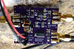
For the connectors, I used SMA end-launch connectors. This compact setup means the board could be mounted in an enclosure and connected to bulkhead connectors of any style (BNC and N are used in the 11947A) using short coaxial cables.

agilent-11947a_manual.pdf

Original HP manual with schematic and layout

Adobe Portable Document Format - 616.47 kB - 12/06/2019 at 20:44

Preview
Download

sheet - 12.46 kB - 12/06/2019 at 20:39

Download

11497B.zip

Gerber X2 files

x-zip-compressed - 9.55 kB - 12/06/2019 at 20:39

Download

  • S11 measurements

    James Wilson12/14/2019 at 00:49 0 comments

    One thing I forgot to characterize was the reflection measurements (S11 and S22). The 11947A datasheet cites a VSWR of < 1.7, and < 1.3 below 50 MHz for the input port. Setting up the board on the VNA, I measured S11:

    The value at 200 MHz is 1.16. Well within spec, even beyond the operating range. Looking at the output port:

    Also within the original spec of output port VSWR < 1.8, and < 1.2 below 50 MHz.

  • Assembly and test results

    James Wilson12/06/2019 at 20:32 0 comments

    After assembling the prototype boards, I measured their performance on a R&S FPC-1500 SA & VNA. The attenuation stays 10 dB nominal until around 250 MHz, which satisfies the upper limit spec of 200 MHz.

    Since the FPC-1500 measurement range bottoms out at 2 MHz, I examined the low-frequency performance on an oscilloscope using the Bode chart/frequency response analysis. For this configuration, the 11947B output is connected to the scope port via a 50 ohm feed-through termination to have 50 ohm source and load impedances. The low-frequency roll-off occurs around 5-6 kHz with a flat response up to 1 MHz.

    To examine the limiter performance, I stayed on the oscilloscope and increased the generator amplitude. The limiter becomes active (+10% increase in attenuation) at +14.6 dBm input power. The HP datasheet has the limiter threshold at +17 dBm, a close match.

    Increasing the generator output further, the limiter distortion becomes highly visible. The top output voltage is 600 mV. An upper bound on the output power would be a square wave with amplitude of 600 mV for a RMS voltage of the same. At a system impedance of 50 ohms, the power output is limited to +8.6 dBm.

    All told, the attenuator and limiter function well within spec and on the first board spin. Thanks HP engineers for the excellent design!

View all 2 project logs

Enjoy this project?

Share

Discussions

Guido wrote 03/08/2023 at 22:46 point

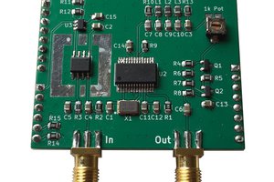
Many thanks, James, my clone works very fine!

Great project!

  Are you sure? yes | no

James Wilson wrote 03/08/2023 at 23:16 point

You’re welcome and good luck! 

  Are you sure? yes | no

Alex wrote 10/23/2021 at 14:17 point

Hi James! Could you share the schematic?

  Are you sure? yes | no

Dieter Vansteenwegen wrote 12/16/2019 at 16:13 point

What kind of PCB material have you used? FR4 or something more specific to RF?

  Are you sure? yes | no

James Wilson wrote 12/16/2019 at 17:04 point

Board specs are 2-layer Technolam UV Block FR-4-86, 1.6mm thick. It's a low-frequency design of small size, without strict loss requirements, so FR-4 still offers good performance and sure is more economical!

  Are you sure? yes | no

Dan Maloney wrote 12/09/2019 at 23:46 point

That was cool, thanks for posting this - I learned a lot.

  Are you sure? yes | no

Similar Projects

Does this project spark your interest?

Become a member to follow this project and never miss any updates