Close
0%
0%

High performance dorm room CNC

A (sort of) low cost CNC with broad capabilities and low storage volume

Public Chat
Similar projects worth following
As the access to the workshop at my university is a total mess and I want to greatly improve my home prototyping capabilities, I'm currently designing and building a CNC that i can use in my room.
to be able to do this project, the entire CNC has to be able to be stored under my bed. this means i have only 20 cm of height available. Width and depth are not such a big problem as i have a pretty large bed.

The end result should preferably be pretty sleek and professional(ish).
If interest is shown, i will make the source of everything freely available and proper build and assembly documentation can be made.

And of course as a disclaimer, with "high performance" I mean high performance in the diy cheap cnc realm ;)

The main goals of this design are:

  • Design has to be cheap(ish); parts i can get for free through contacts won't be seen as costs, as is stuff like the water-jet cutter i can use for free at my university. 
  • Can fit under my bed for storage when not in use
  • Minimal disassembly effort and time required for storage
  • Repair-ability and expand-ability integrated into the design
  • Can machine at least aluminium parts with acceptable accuracy (0.05mm tolerances are a absolute minimum, higher precision preffered).
  • 3D printed parts only used when it's right for the job, not like pretty much every other build project these days.
  • A 3D touch probe has to be mountable for indexing and future use as a improvised CMM.
  • Future upgrades may include BLDC motors for X and Y motion

CNC Mill V4.3.pdf

This is a 3D PDF of the assembly, not sure if this will work. But i'll see. You may need to download it and open it in Adobe Reader.

Adobe Portable Document Format - 3.68 MB - 12/17/2019 at 16:31

Preview
Download

  • A bit of progress

    Oscar S.01/21/2020 at 22:25 0 comments

    So, it's been a while since the last update. However it's mostly been waiting for parts to arrive from china. But in the mean time i've made some progress. 

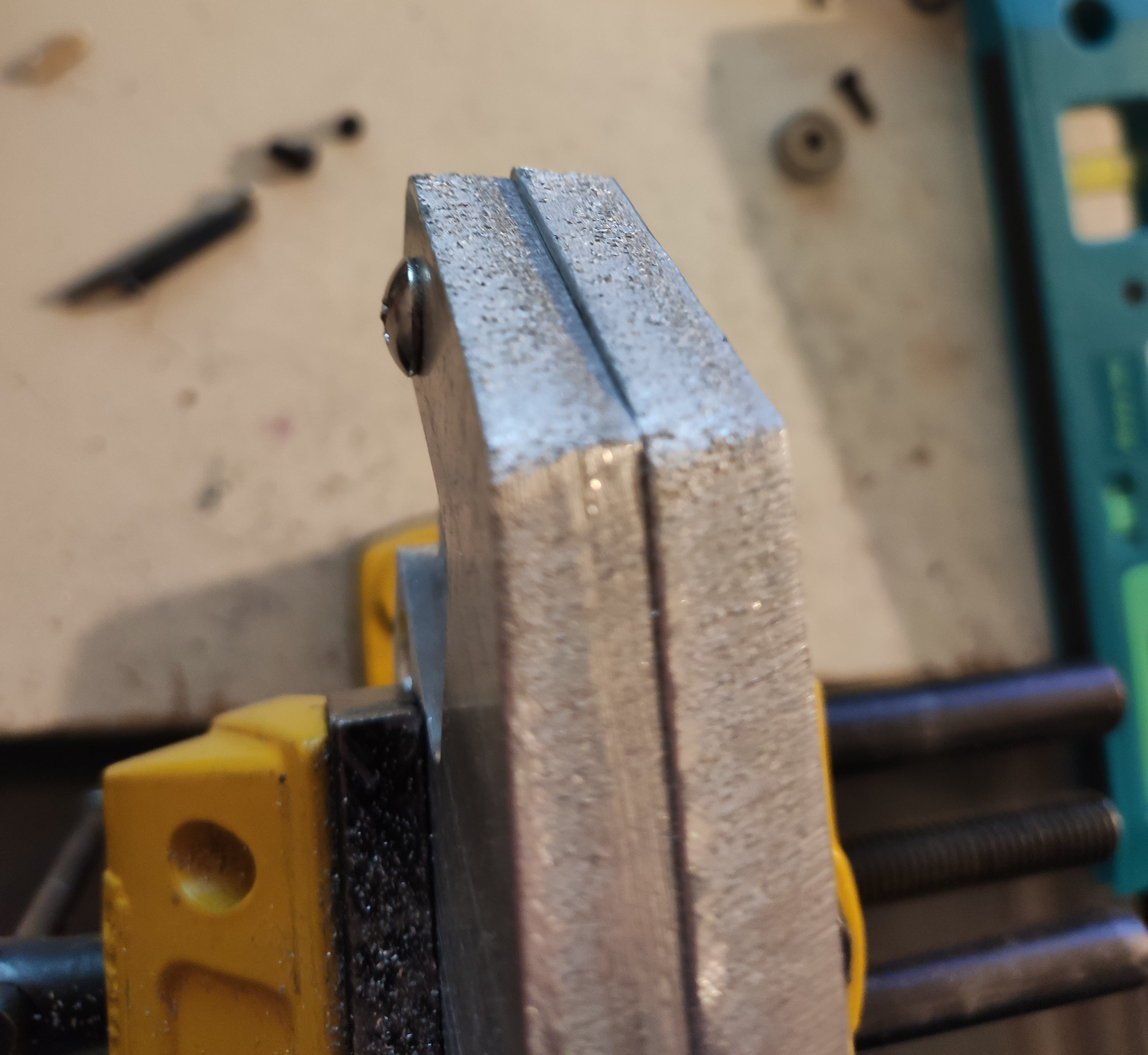
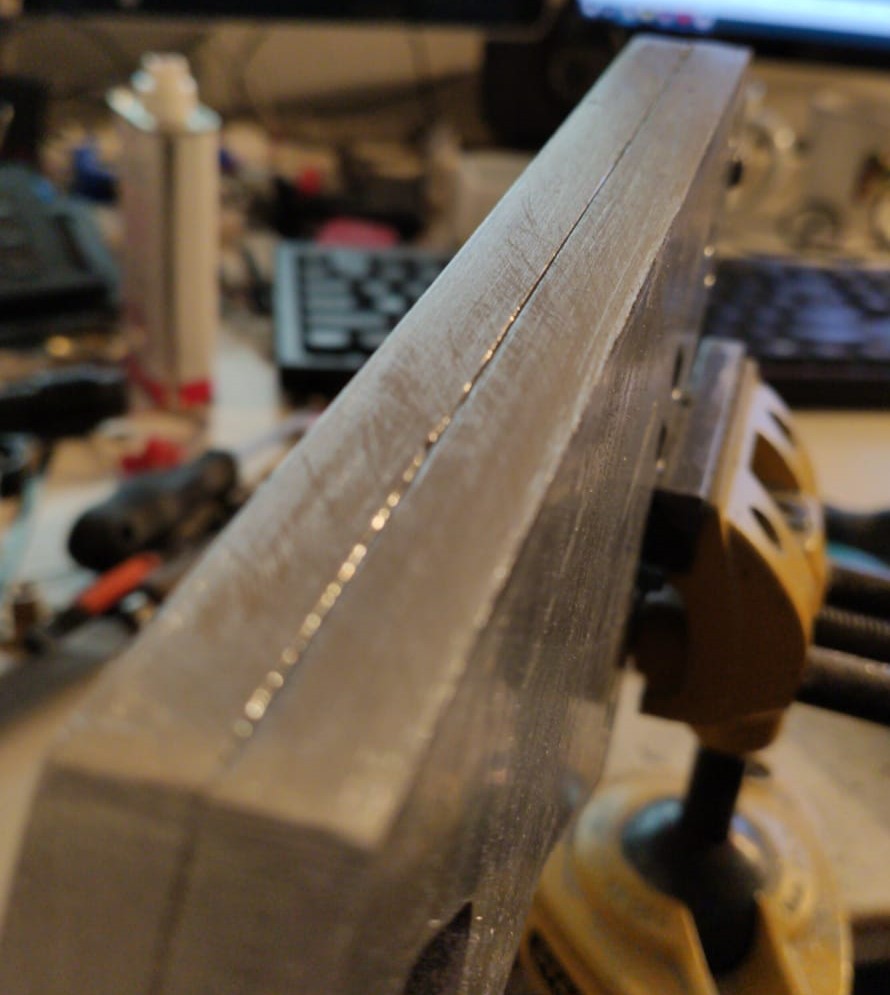
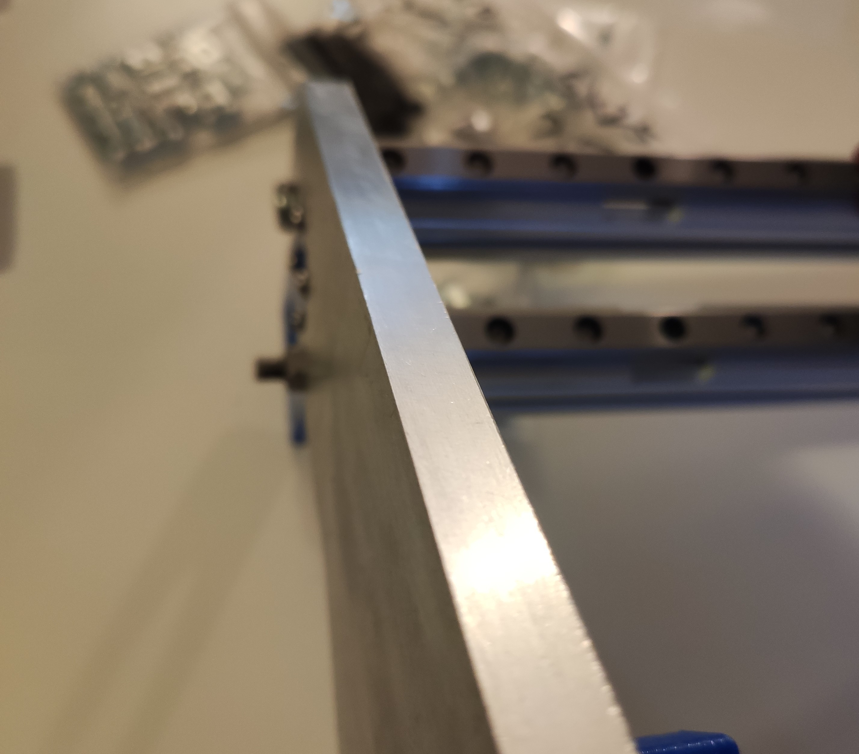
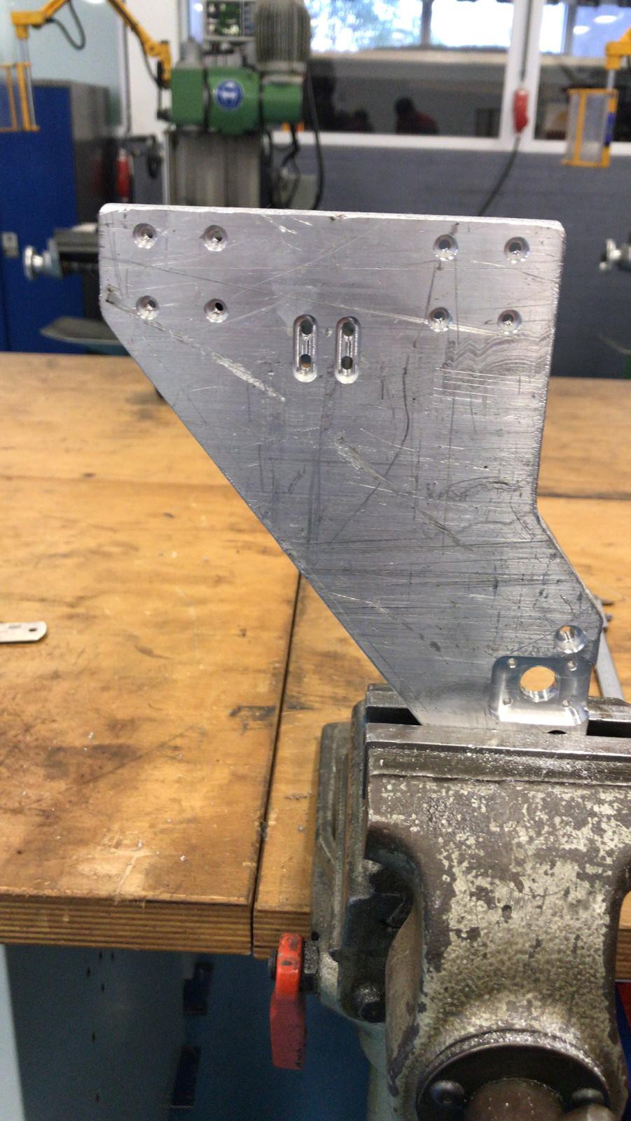
    firstly, the sides of the gantry plates were awful, the mounting holes are machined, but the outline was done on a plasma cutter to save time. so i spent an entire evening filing and anding the sides clean and flush to make it all seem way nicer to the eye.

    The sides of the gantry plates as received

    so i'm pretty happy with the result after some hard manual work

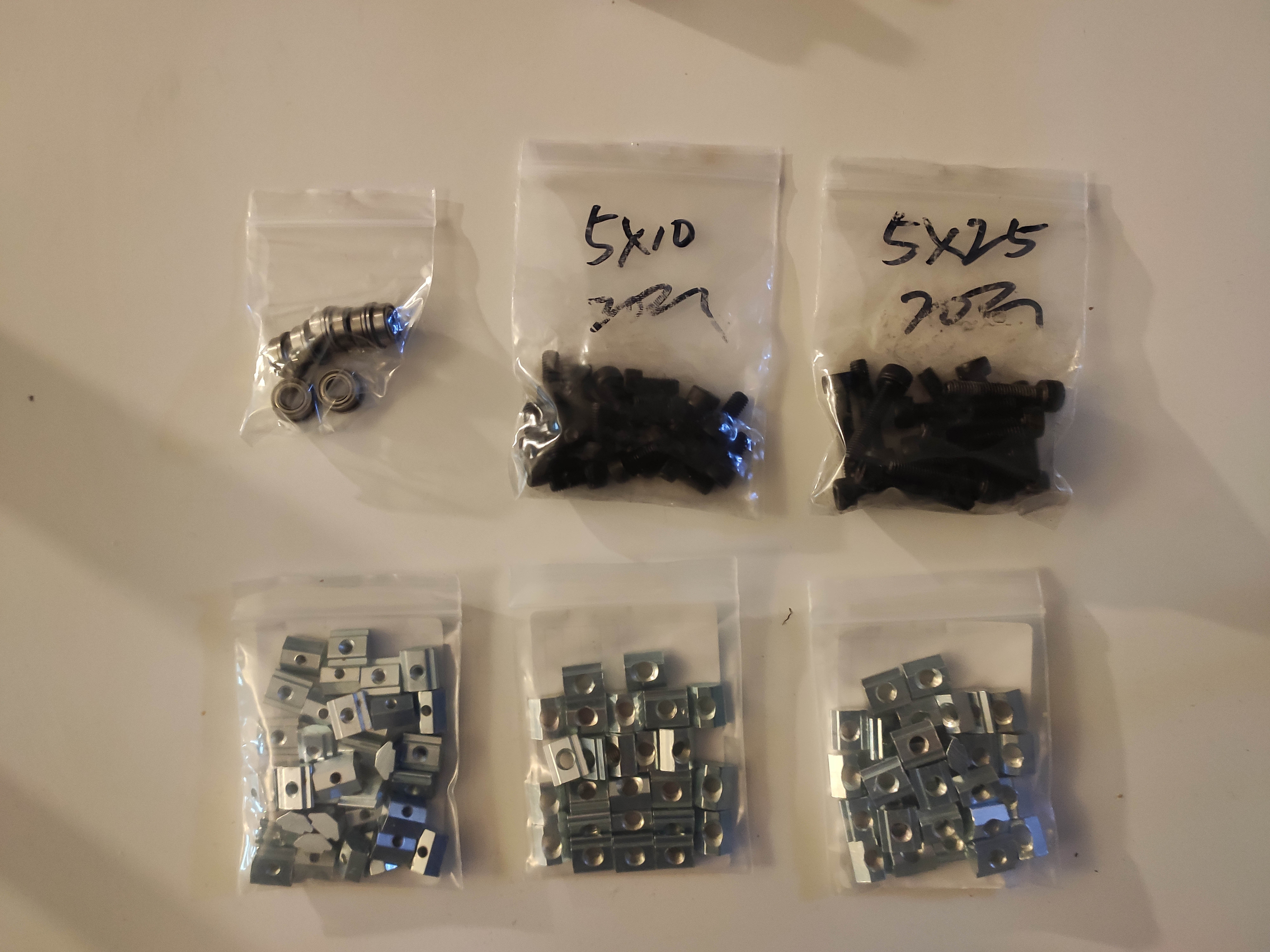
    secondly, all the MGN rails and almost all of the carriages are in. Also some M3 Bolts, M5 bolts, T-slot nuts, spacer plates and 2020 extrusions have been received. So i've been able to start assembling the y-gantry. 

    pretty happy with the overall fit and finish. The  blue printed motor mount plate is just a temporary place holder to check the design. 

    I designed the gantry plate to be mounted with M5 bolts to the 2020 extrusions. Now did i find out that the extrusions i ordered had a larger inner hole, so i've drilled out the gantry plates and mounted the gantry plates with M6 bolts, however i just had one bolt laying around, so it is temporarily improvised with a threaded rod and a bolt as you can see. But i ordered the right bolts and should be a drop-in replacement once i have those.

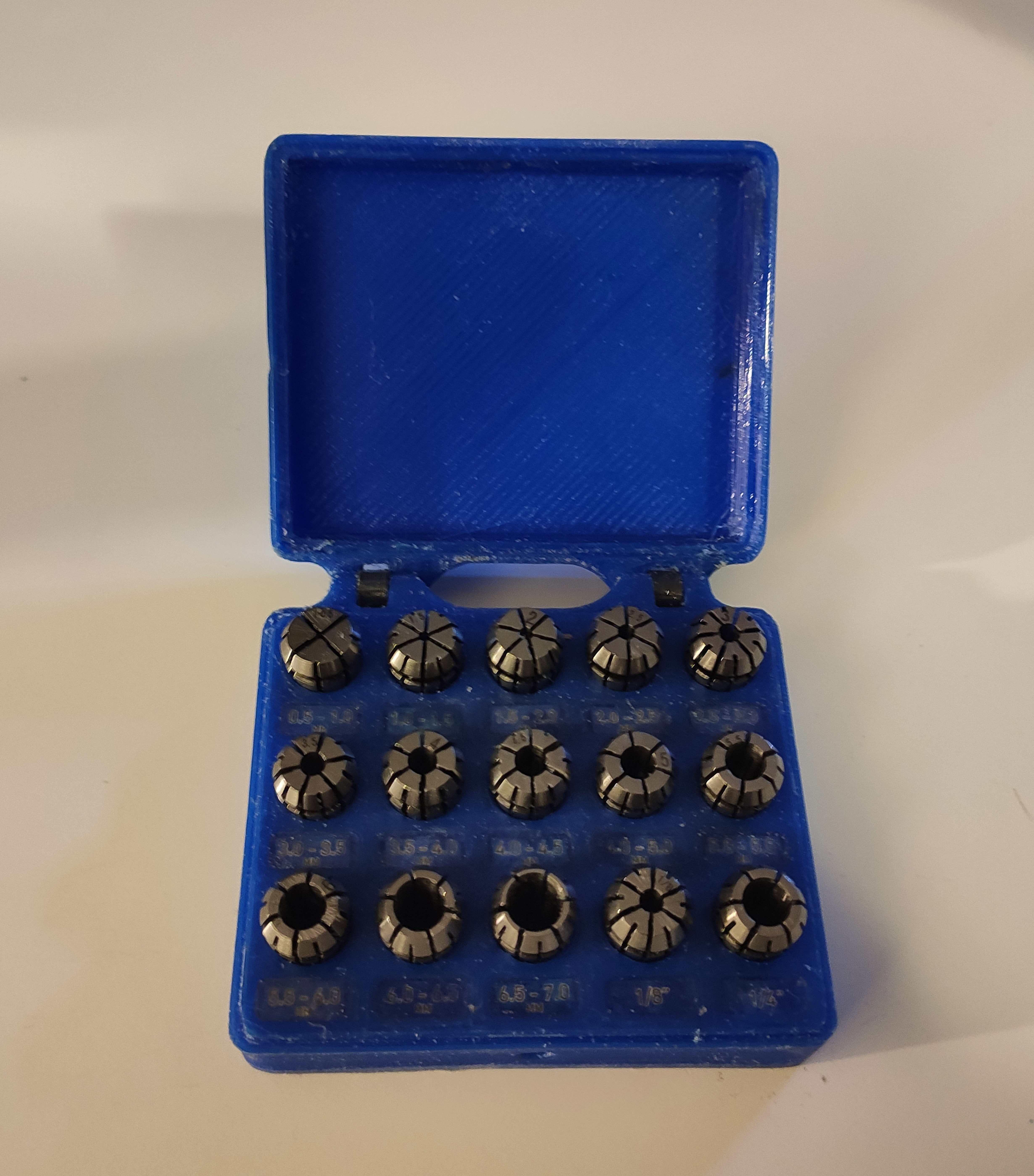
    after i got my new ER11 collet set in the mail, i designed and printed a nice small box for it to prevent me from losing them.

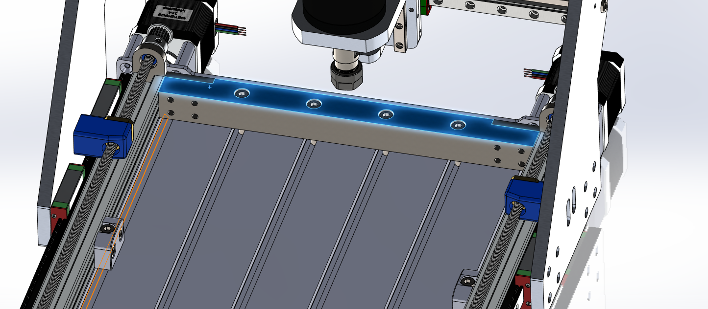
    and lastly i remembered i had a random block of scrap metal laying at my parent's house wich would be perfect for the front and back frame rigidity improvement brackets (i'm not actually sure what to call them, see the last log. those).

    i've contacted someone from my uni to check when i can access the workshop to machine this block to finish. But as the other 2020 extrusions are not yet in, there's no real reason to hurry. 

    For the next few weeks i'll be focussing on my examns so i'll probably post an update as soon as the complete frame is ready for assembly.

    It's great to see the interest in my little project!

  • Base design finalization

    Oscar S.12/17/2019 at 16:31 0 comments

    So after considering Paulvdh's comments, i came to the conclusion that the base did lack rigidity and I wasn't quite happy with the assembly. The design relied too much on proper assembly and tramming and not enough on proper machining. As i'd rather spend an hour or two extra in the workshop so i can just throw the parts together and have them aligned and square and everything. 

    I've decided to add about 20 euro's of steel and an extra day of workshop time to improve the base.

    The width of the base is now determined by a big chunk of precisely machined steel in the front and back instead of waterjet cut sheet steel. This will also greatly improve the rigidity of the base plate, and add some mass to the whole thing.

    I've decided that this will be the final design for now, and will start making the drawings and buying the rest of the parts. The MGN rails i ordered this black friday are also in, so progress is coming.

    I've uploaded a 3D pdf of the latest version. Interested people can take a look at this. Tips are still welcome and will be considered.

    I'll probably be busy and away this christmas, so the next update will probably come somewhere around the half of januari. Happy new year everybody! ;)

  • Side plates done!

    Oscar S.12/14/2019 at 15:50 0 comments

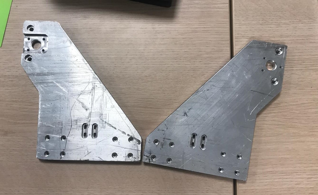
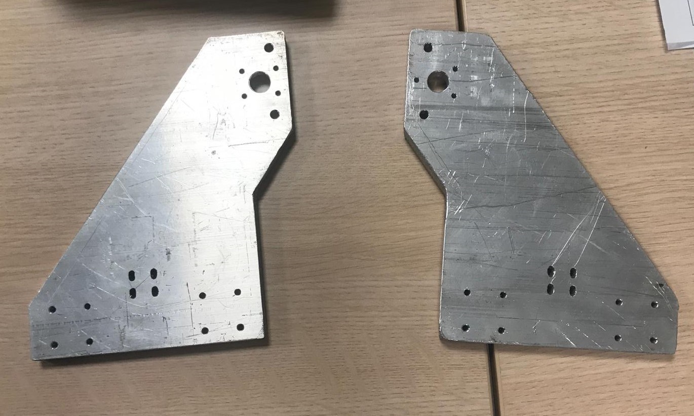
    So, the side plates are done! My friend did a perfect job, and i will only need to sand the surfaces for aesthetics.

    Side plates machined  - front
    Y Gantry side plates - back

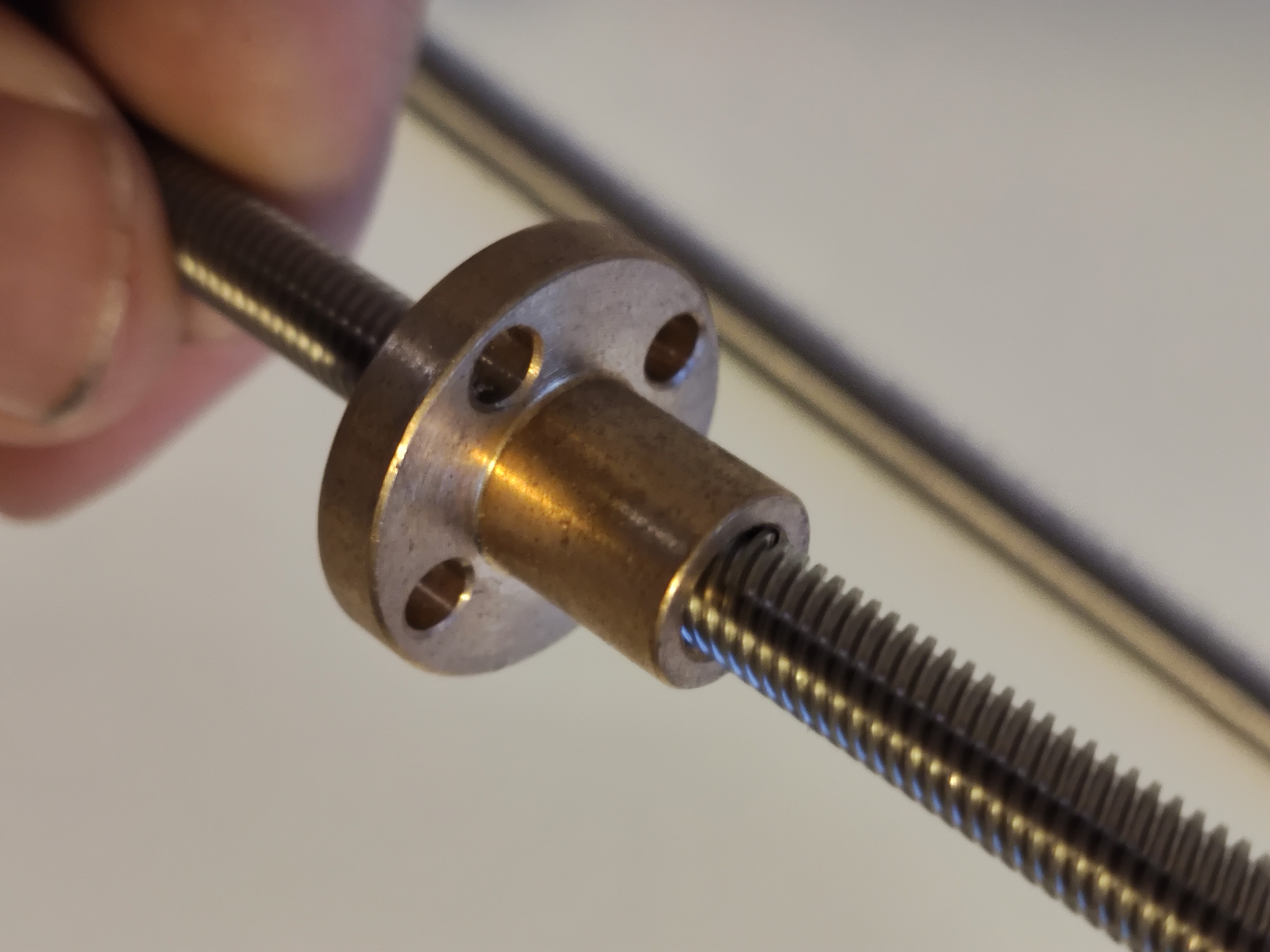
    Secondly, the Leadscrews for the Y-gantry are in! they are okay-ish quality, but the nuts have a completely unacceptable amount of play in them. so i will have to find new ones. Although i had a known good quality nut laying around and that worked perfectly without any noticeable play, so the rods themselves are good (enough, for now at least).  

    i will probably throw them in a lathe for finishing sometime next week.

    500mm TR6*6 leadscrews - Y gantry
    The crappy nut that came with the leadscrew

  • Small design change

    Oscar S.12/12/2019 at 17:38 0 comments

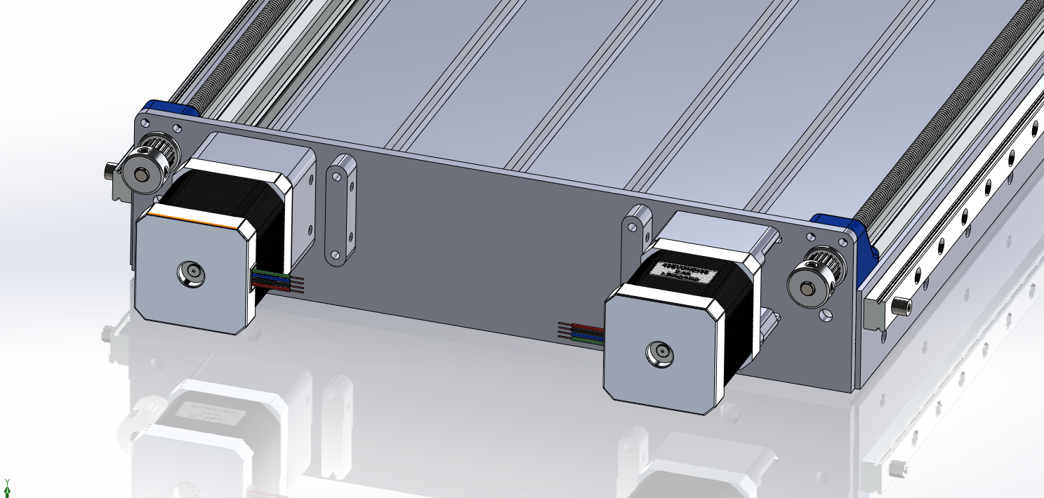
    So i decided to change the Y-axis motor configuration. The design used to use one single NEMA17 Motor with a 600mm closed GT2 belt to drive the two leadscrews synchronously. However to simplify the tramming and tweaking of the physical unit, I decided to change it to two motors each driving it's own leadscrew.

    Also, both Y-Gantry side plates are done, i'll post the result later on.

  • Y-Gantry side plates and animation

    Oscar S.12/11/2019 at 15:57 0 comments

    So the project has progressed a bit again. The side plates are in the making and almost finished today, just some cleaning, sanding and finishing up to do.

    Y-gantry Side plate  - in progress

    Secondly i finished the render of the CAD model that shows the folding mechanism. Note: Due to the fact that my trusty dual Xeon e5645 isn't really cutting it anymore these days, i had to remove pretty much all the screws from the model. However the Z-gantry is fixed with four large bolts and aligned with a tolerance fit. the animation doesn't really show this. But the bar linkages that allow the Z-axis to fold down are just for easy folding and reassembly and bear no structural loads at any point during actual use.

    I'm currently looking into the Electronics side of things. At first i was planning on using a simple modified 3D printer electronics setup, pretty much like my Kossel 3D printer does. And then throw something like GRBL on it. However i'm not really sure that's the best option for this build (possibly linuxCNC or Mach4?). if anyone has any suggestions, be sure to comment, chat, mail or use carrier pidgeon whatever floats your boat.

  • The project beginning, first cuts and placed orders

    Oscar S.12/09/2019 at 16:06 0 comments

    So to start i have received the base plate and cut the side plates on a plasma cutter that i could use for free. 

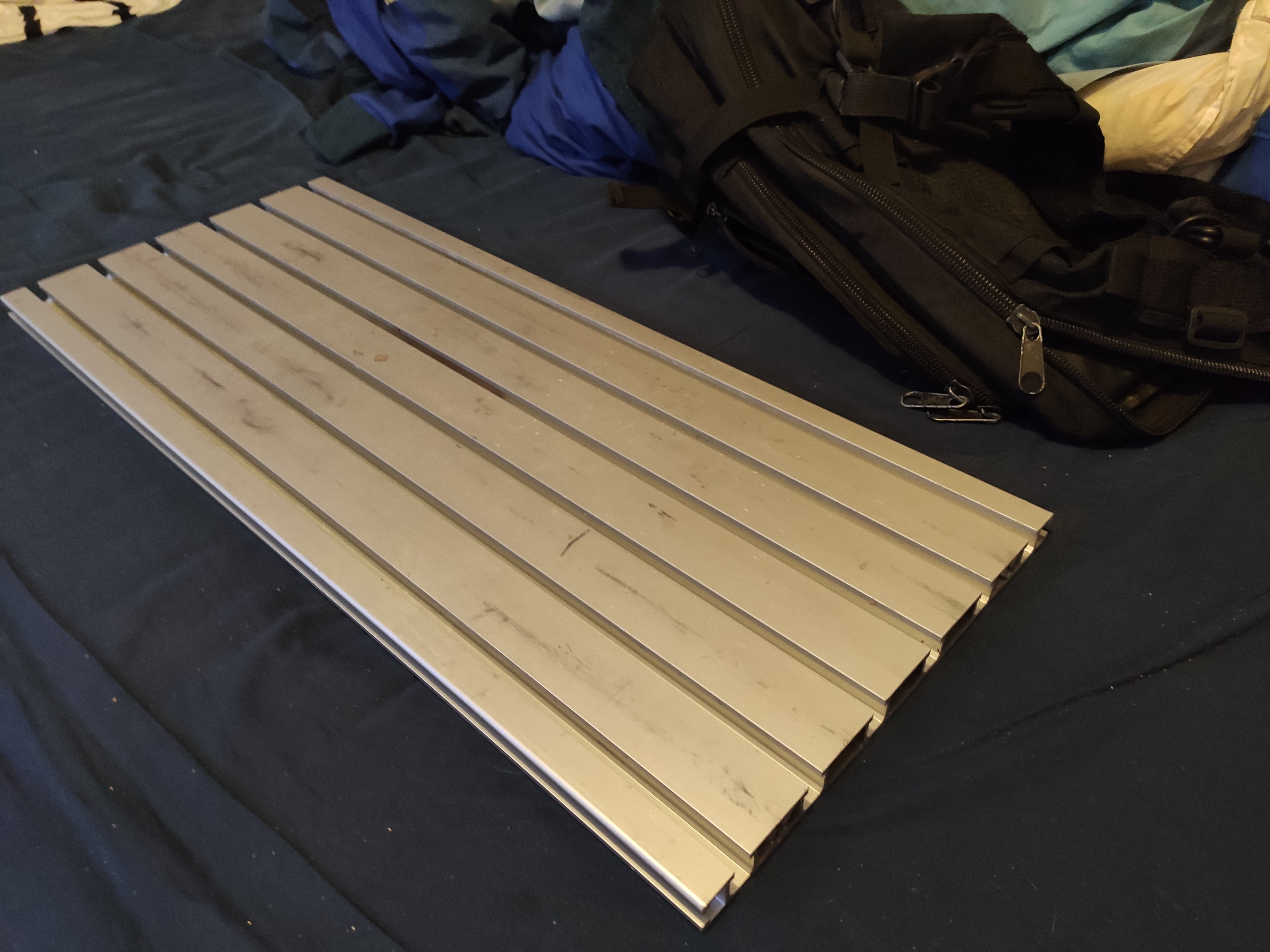
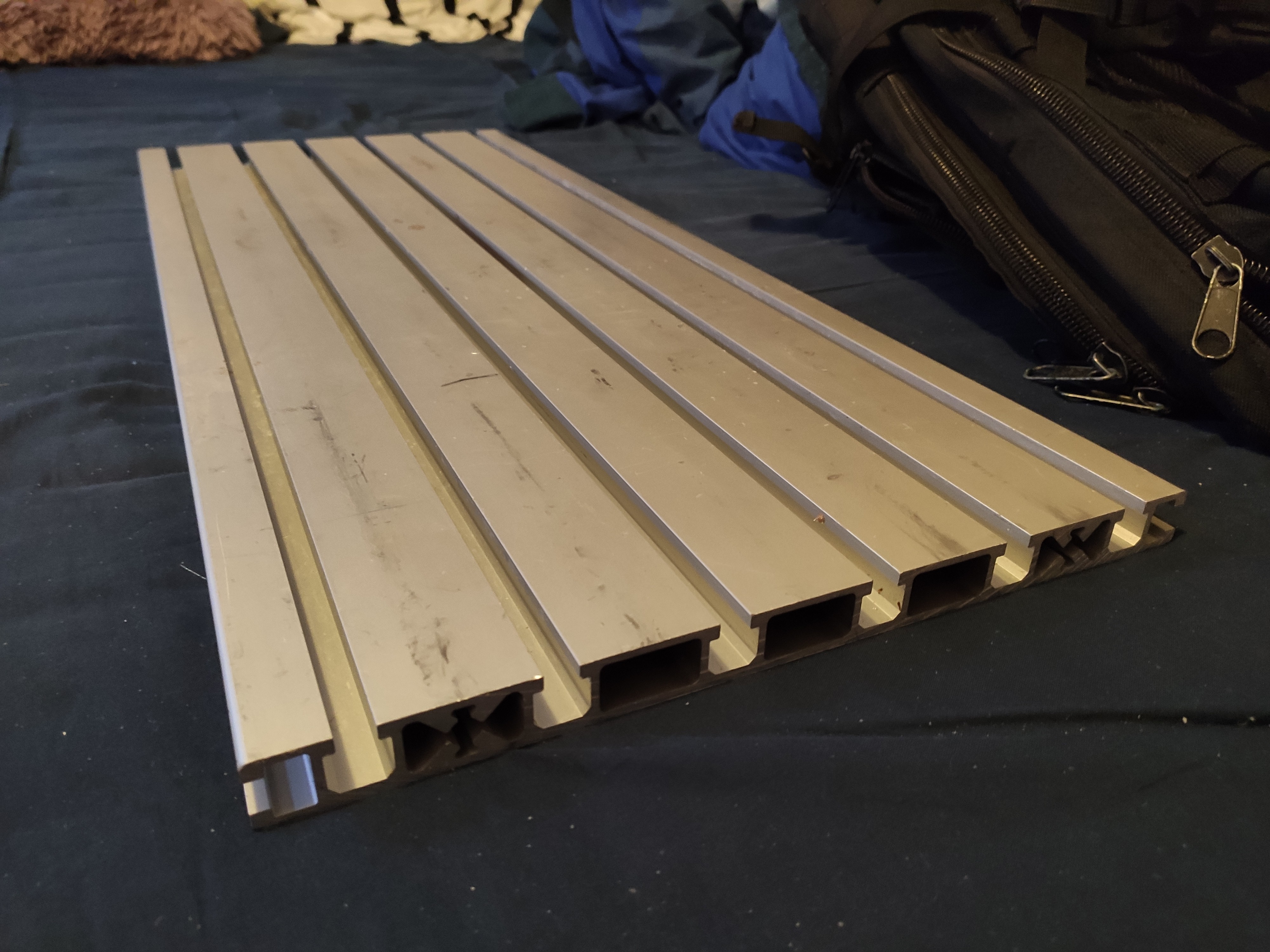
    and here is the base plate for the design. It's a 19x270mm T-slot aluminium extrusion. Usually pretty expensive stuff this, but a friend did me a favor and got it for free for me.

    The baseplate as received
    A better look at the profile

    further, on black friday i ordered as much parts as i could affort at that time to save as much money on this project as i could. The parts were going to be ordered anyway, so why not with 50% off. 

    these include:

    • two MGN12 500mm rails
    • two MGN9 300mm rails
    • two TR6x6 500mm leadscrews 
    • various t-slot nuts and bolts

    The design is currently being finalized with pretty much only some tweaks left. I will upload more pictures and renders in the coming few days. 

View all 6 project logs

Enjoy this project?

Share

Discussions

Jason Cho wrote 01/06/2020 at 23:09 point

This... is really cool. I am looking forward to hearing more about this!!!

  Are you sure? yes | no

Oscar S. wrote 01/17/2020 at 11:42 point

Hi, I'm currently waiting for parts to arrive. I will post a new update soon :) 

  Are you sure? yes | no

paulvdh wrote 12/13/2019 at 09:49 point

Another tip:

This sort of router setup almost always lack in the rigidity department.

The aluminimum baseplate you are using  is quite flexible, but it's also already better then others I've seen. An easy way to add more rigidity to this base plate is to make a sandwitch construction by glueing a sheet of plywood (or MDF) to the underside of your baseplate and glueing a sheet of aluminimum under that. The plywood is mostly used to generate a bit of distance between the aluminimum sheets. Twice the thickness is 8 times the rigidity!

  Are you sure? yes | no

Oscar S. wrote 12/18/2019 at 01:15 point

I've changed the design so it has a lot more rigidity. thanks for the input ;) 

Ideally i would use your method of adding rigidity, however with the current design i have only 6mm clearance to fit it under my bed. and because of the fact i only have the space for this project if it fits under my bed, would be cutting my Z-height with your method, however the side plates are already made and the machining and materials were a one-time favor. so that can't be done anymore. But i think my current redesign is a good compromise (at least i hope so, haha).

  Are you sure? yes | no

paulvdh wrote 12/13/2019 at 09:31 point

I've also been interested in CNC stuff for a long time and my first go was with completely self written software (Internet was not a big thing back then). Later I got interested in LinuxCNC and the combination of Maxhinekit + Beaglebone. I was however not very happy with the quality of the software. Machinekit uses the PRU, but (at least back then) it used only one of the PRU's for both stepper timing and some other stuff (plc like behaviour? And I was not in the mood to delve very deep into that software. I also did not want to add another monitor to the setup, and running machinekit over SSH resulted in a very sluggish user interface. (Think 3 frames/second)

I'm not completely sure, but it seems that the beaglebone is a bit underpowered for handling SSH and a GUI at the same time. If you want to do a good LinuxCNC setup, then a Mesa card (FPGA which handles stepper timing) is highly recommended, but this will add about USD200 to the setup. I was willing to invest in such a setup, but what held me back is that I already built a cabinet with stepper motor drivers, frequency inverter, water cooling, power supplies etc, and there was no room left for anything much bigger than a beaglebone board.

So finally I just grabbed a Blue Pill I had lying around and put a a version of Grbl in it for an STM32. This runs very nicely, and I can highly recommend this setup. As I only needed a breakout board I just put a socket and a few connectors on a PCB and soldered it with lacquered wire. (I already built the cabinet with external steppers Think 112mm long Nema 23 here.

There are number of GUI's for Grbl, some are quite simple / basic, and others have more built-in functionality. I wanted to have lots of options, and the first program I tried was bCNC.

bCNC has some rudimentary CAM facilities for milling. For example you can import an .dxf file and then apply offsets with your mill radius and generates ramps for lead in and even add tabs to hold your workpiece in place after milling.

CAM functionality in bCNC is pretty basic though and later I intend to switch to FreeCAD with the Path workbench, but as of now I'm not sure if it has been developed enough to be fully functional.

Also: Sometimes I use bCNC go generate G-code from a .dxf file, then save the G-code and edit it with a text editor, and then reload the G-code in bCNC. bCNC also has some built in editing functions and what to do how will need some experimentation and also depends on personal preferences. But altoghether I'm quite happy with the combination of Grbl in an STM32 and bCNC.

I would avoid using an AVR (arduino) in this setup, for the simple reason that most of them run on a 16MHz crystal, and that is not well suited for reliable serial communications. (And you want your communication rock solid! With the Blue Pill it uses the hardware USB interface and CDC. On my linux box (I do not use windows, nor that rotten fruit brand) support for CDC is built in, and bCNCsimply connects to /dev/ttyACM0. No need to install any drivers.

Also: I assume you already have a PC. A Blue Pill costs around USD2, which is negligible.

If you don't like soldering you could try an "arduino board" with a "cnc shield", but you will have to set the "X2" fuse for serial communication or swap the crystal for reliable communication. RS232 has around 2% error margin in the baudrate, and the wrong choise of crystal in the "arduino" boards eat up most of that margin. It's one of the many reasons I do not like "arduino" much.

  Are you sure? yes | no

jasonbm123 wrote 12/12/2019 at 04:58 point

I  need one of these for my dorm room too. :)

Will you publish the files?

Thanks.

  Are you sure? yes | no

Oscar S. wrote 12/12/2019 at 17:43 point

I will as soon as the main design is mostly fixed, Currently i'm constantly tweaking and adding stuff.  And i need some time to actually clean everything up and put everything in a logical order. I hate crappily dumped deisgns online. I want to do it the right way :) 

  Are you sure? yes | no

Dan Maloney wrote 12/09/2019 at 23:35 point

And I thought I got luckily when my college roommate has an 80286 PC with an EGA card...

  Are you sure? yes | no

Oscar S. wrote 12/10/2019 at 02:58 point

thanks ;) although I'm not yet sure if my housemates (and neighbours) are going to like the sound of this machine through my paper-thin walls from 1910

  Are you sure? yes | no

Similar Projects

Does this project spark your interest?

Become a member to follow this project and never miss any updates