 wajqnosewicz
Making a tv remote jammer so that no one can stop me from watching my favorite shows.
0%
0%
TV Remote Jammer 1688001
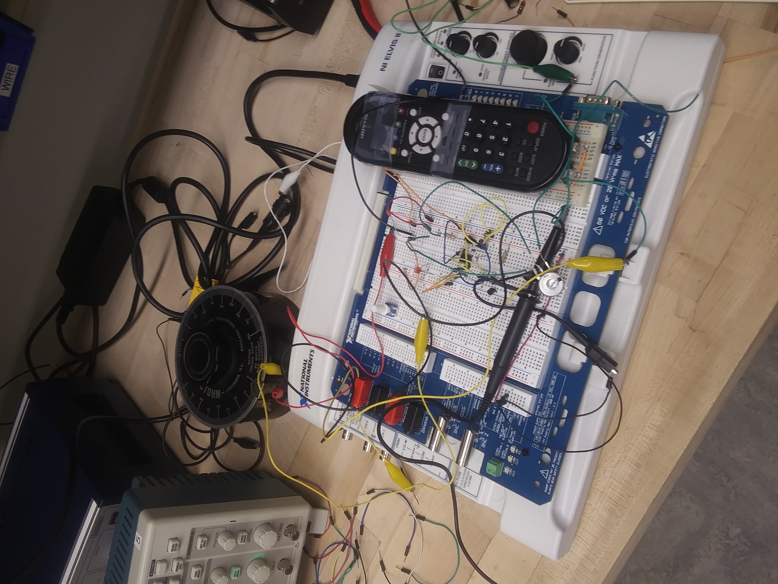
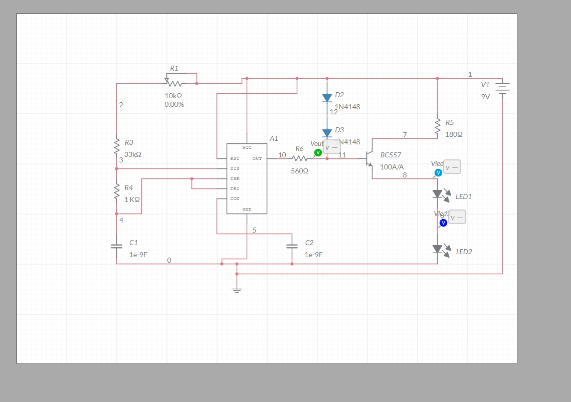
Creating a device that blocks signal from a TV remote
Become a Hackaday.io member
Already have an account? Log in.
Just one more thing
To make the experience fit your profile, pick a username and tell us what interests you.
Pick an awesome username
hackaday.io/
Your profile's URL: hackaday.io/username. Max 25 alphanumeric characters.
Pick a few interests
Projects that share your interests
People that share your interests
 You alreday now..

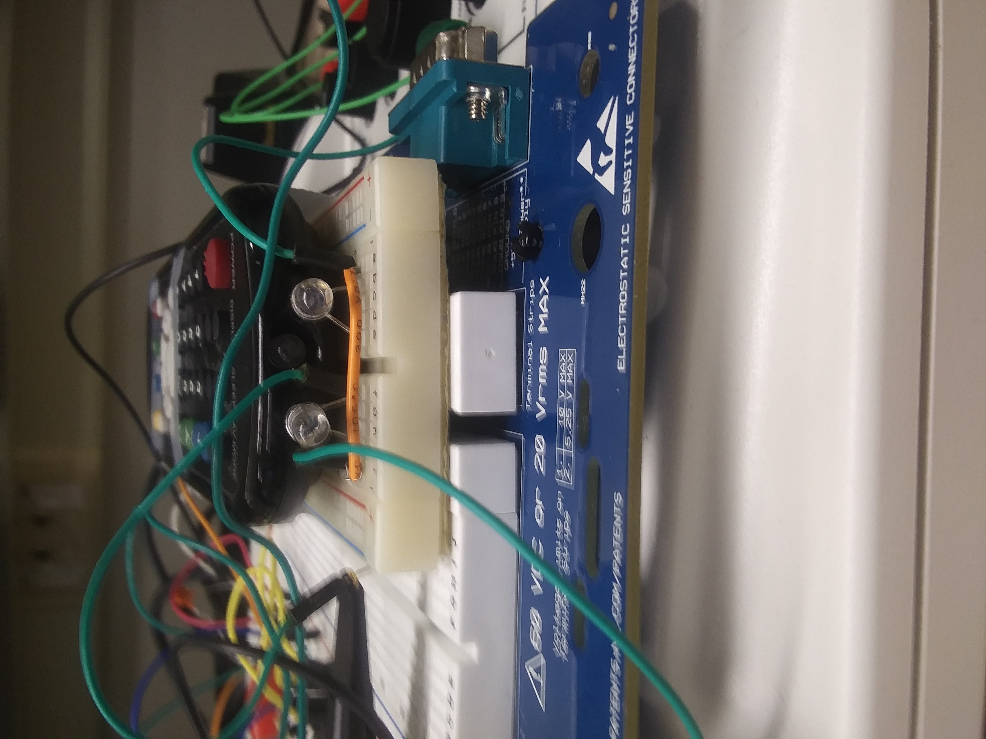
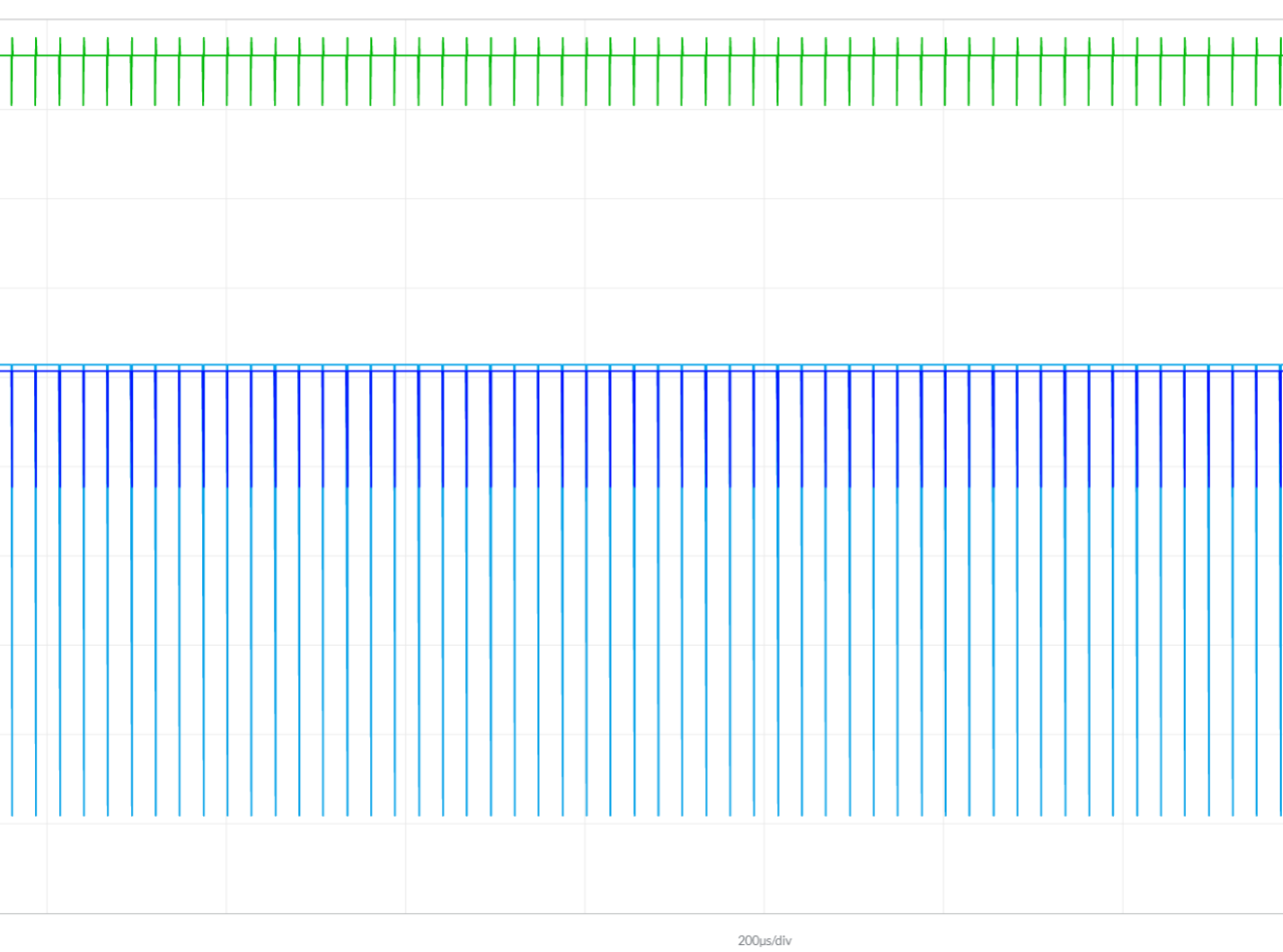
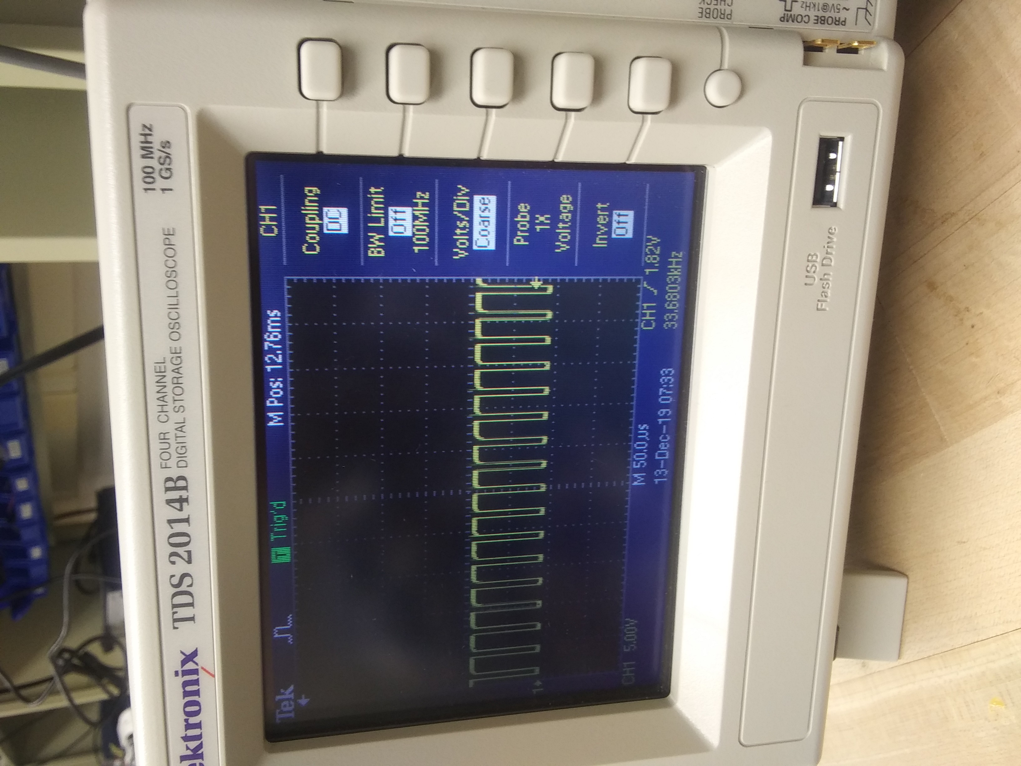
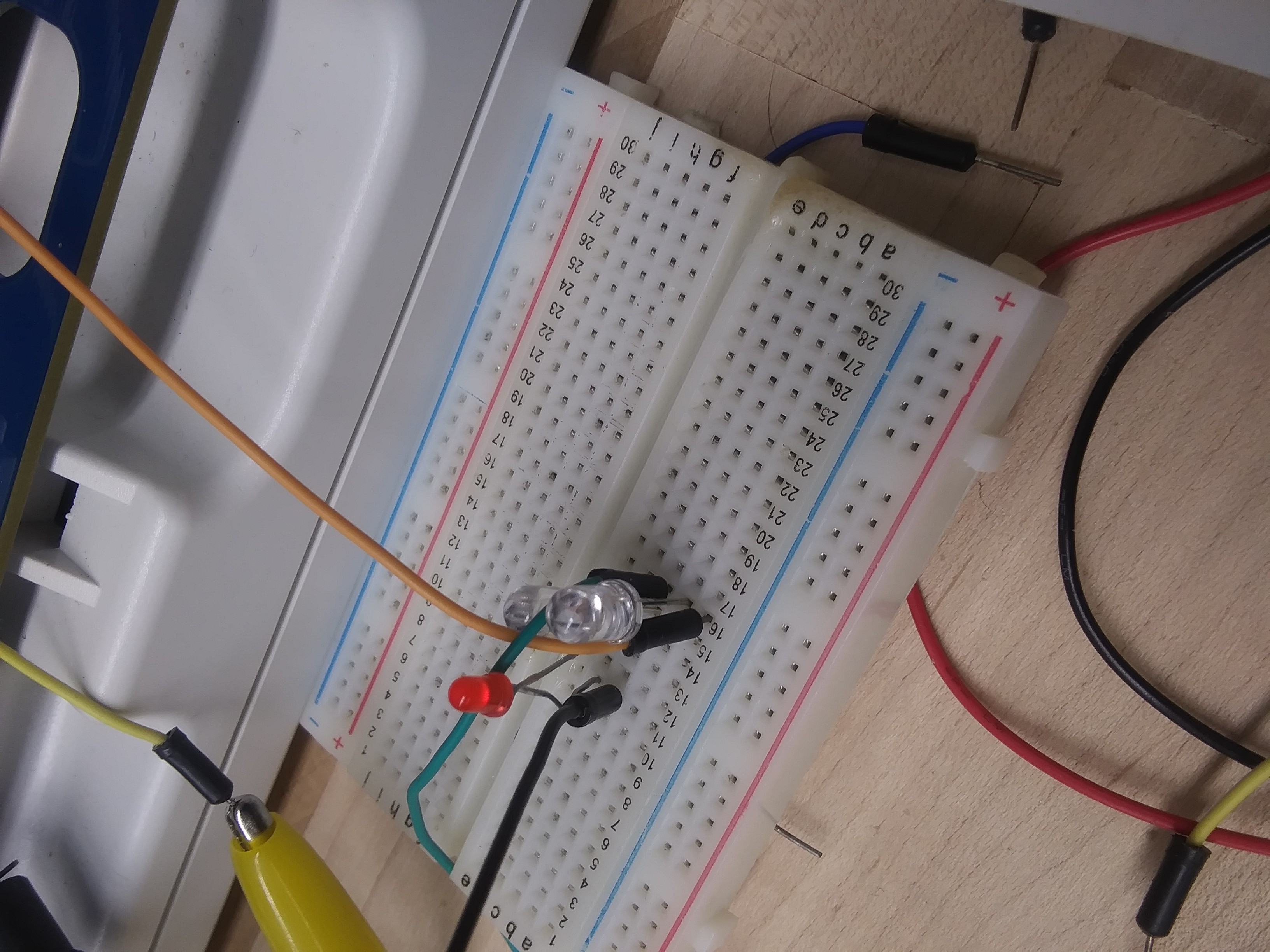 Our infrared light bulbs that we know are sending out a signal.
 MaBe42
 agp.cooper
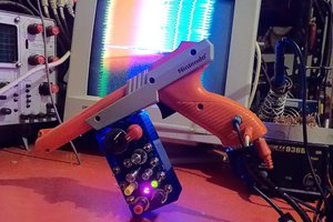
 Russell Kramer
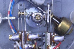
 Yann Guidon / YGDES