Close
0%
0%

Arduino Nano 33 BLE GDB Debugging

Full GDB Debugging with the Arduino Nano 33 BLE and the FT2232H Module with an SWD hack in Visual Micro

timTim
Similar projects worth following
1.1k views
0 followers
Getting GDB up and running with a new board can be as frustrating as the bugs you're trying to fix... thankfully this is all wrapped up now using a run of the mill FT2232H Debugger module, in Visual Micro.

About...

When your project nearly does everything you dreamt it would, those last few bugs can make it feel like it will never work.

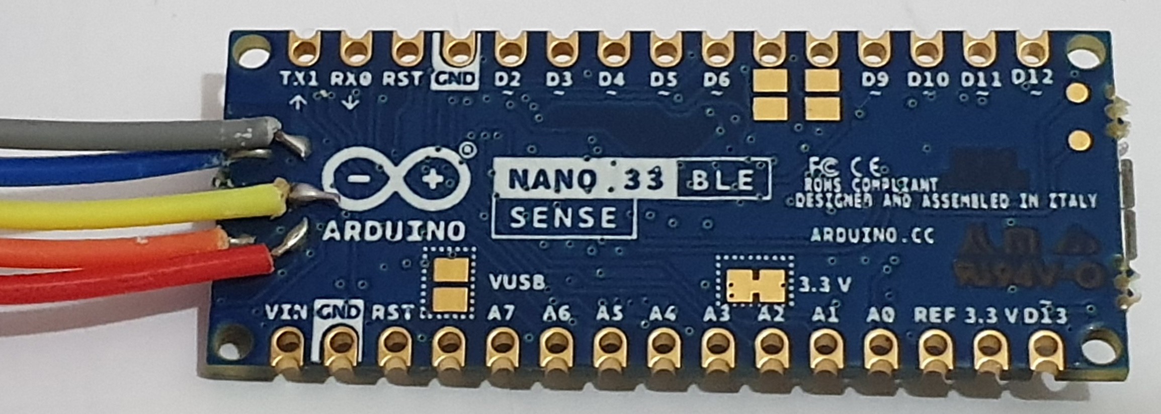
Using debugging tools you can stop and execute your code line by line on your Arduino Nano 33 BLE module thanks to its breakouts, with a little additional soldering.

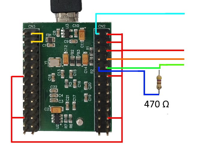
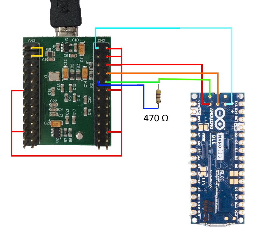
Using Arduino IDE + Visual Micro + Visual Studio set we have the full IDE experience, and all of these debugging tools right out of the box, and the instructions will take you through all the wiring needed to get these working together.

  • 1 × Visual Studio 2017 / 2019 IDE
  • 1 × Visual Micro IDE Plugin to seamlessly integrate Arduino into Visual Studio
  • 1 × Arduino IDE Open Source Software Platform for Embedded Projects
  • 1 × FT2232H Mini Module Electronic Components / Misc. Electronic Components
  • 1 × Arduino Nano 33 BLE Module Arduino Module

View all 9 components

  • 1
    The Soldering

    Before we can connect our Nano 33 BLE board to our external debugger, we will need to connect some jumper wires onto the pads on the back of the board as shown here:

    Location of the solder pads on the Nano 33 BLE (and IoT) board
    Jumper wires soldered onto the BLE debugging pads
  • 2
    External Hardware Debugger

    There are wide variety of hardware debugging devices available, and in this example we will be using the FT2232H Mini Module, which is pre-configured in Visual Micro.

    Note - we only connect one interface of this dual interface module in this example, the second is often used for serial output 

    The FT2232H Mini Module requires some wiring of its own to make it function, which can be completed using the jumper wires, breadboard, and the resistor.

    Wiring Diagram for the FT2232H Mini Module with SWD Hack

    Note: The resistor and wiring configuration here make it compatible with SWD debugging, and is compatible with JTAG debugging already, so you can use it with the ESP32 and STM32 family of boards as well!

    All detailed information about the FT2232H wiring can be found in the datasheet here.

  • 3
    Wiring to the Debugger

    Only 4 wires are needed to attach to the debugger as we are using SWD.

View all 5 instructions

Enjoy this project?

Share

Discussions

Similar Projects

Does this project spark your interest?

Become a member to follow this project and never miss any updates