Close
0%
0%

8-bit Counter

Ever want a display that slowly counts up in binary to 8-bits? Well this project does just that!

Similar projects worth following
This project simply counts up in binary, up to 8-bits. Using two, pre-settable 4-bit up/down counters in series, this counter uses LEDs to visually display this. Started as a side project using found components, it slowly evolved into a PCB.

Will be updating shortly....

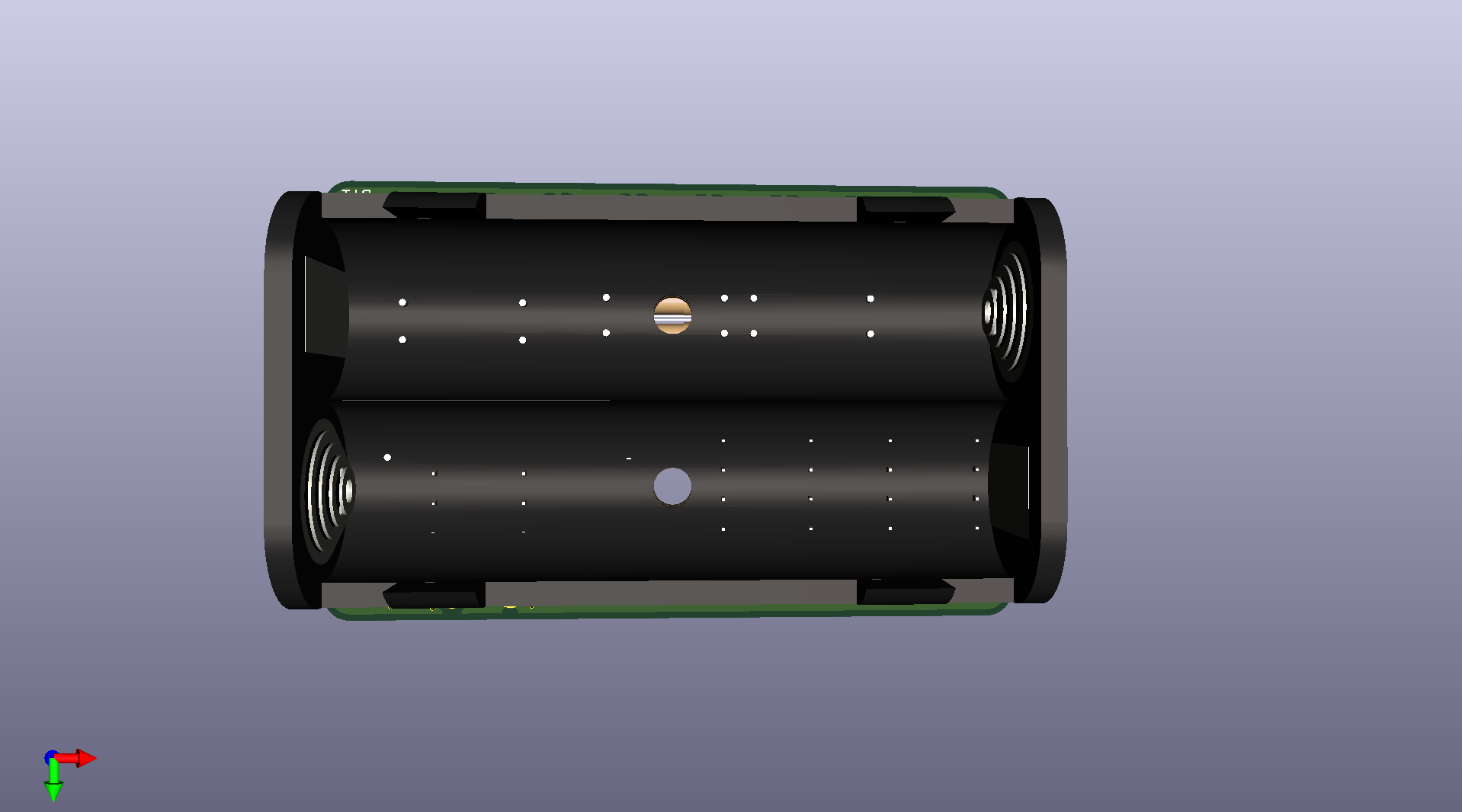
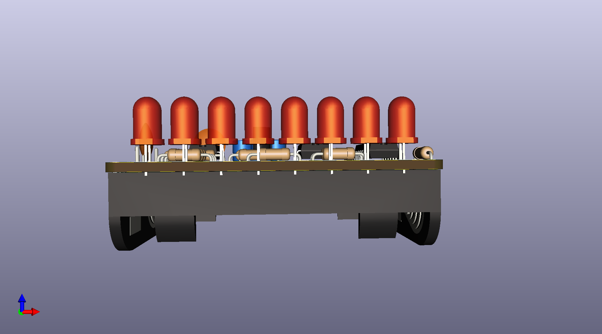
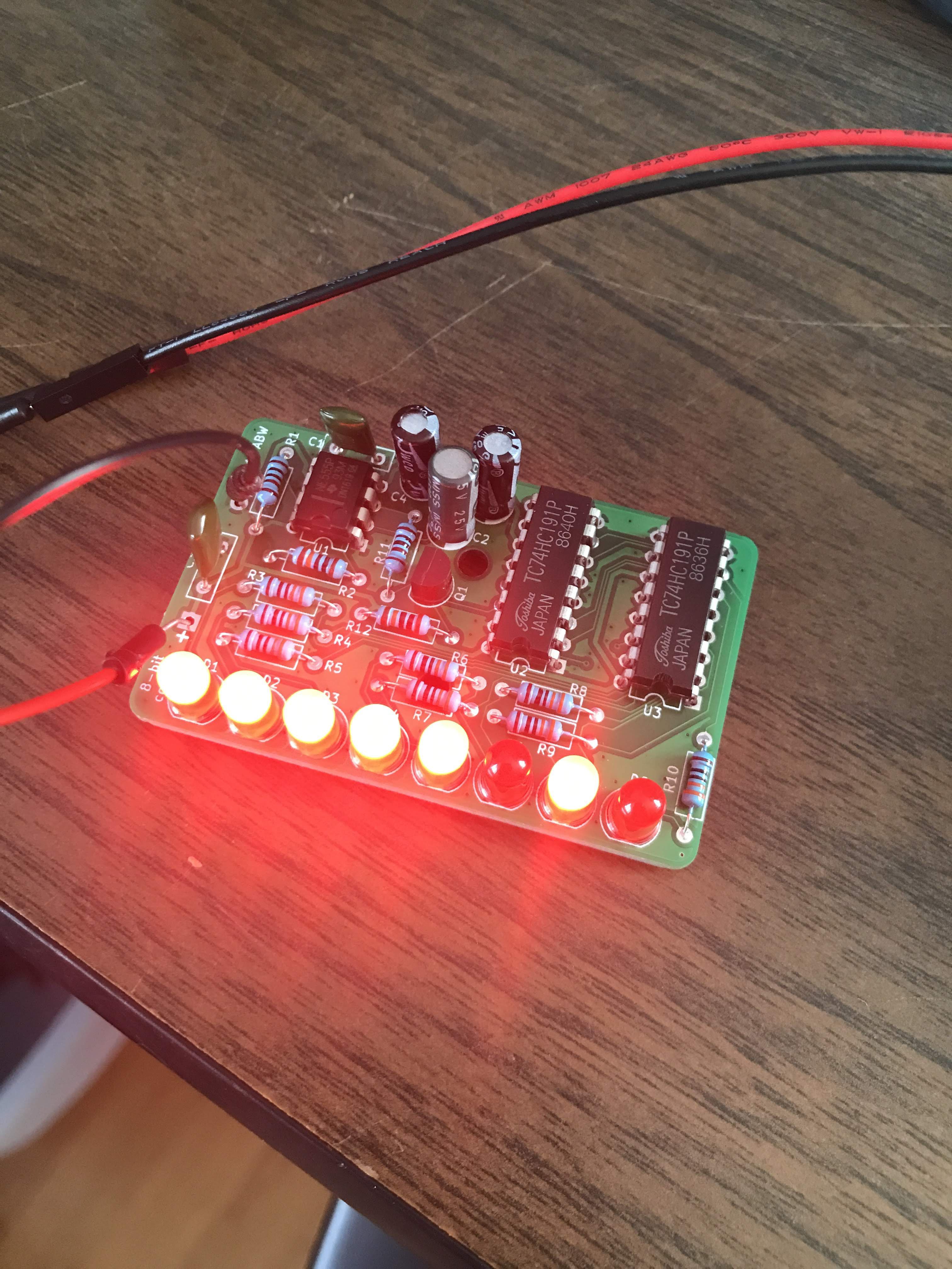
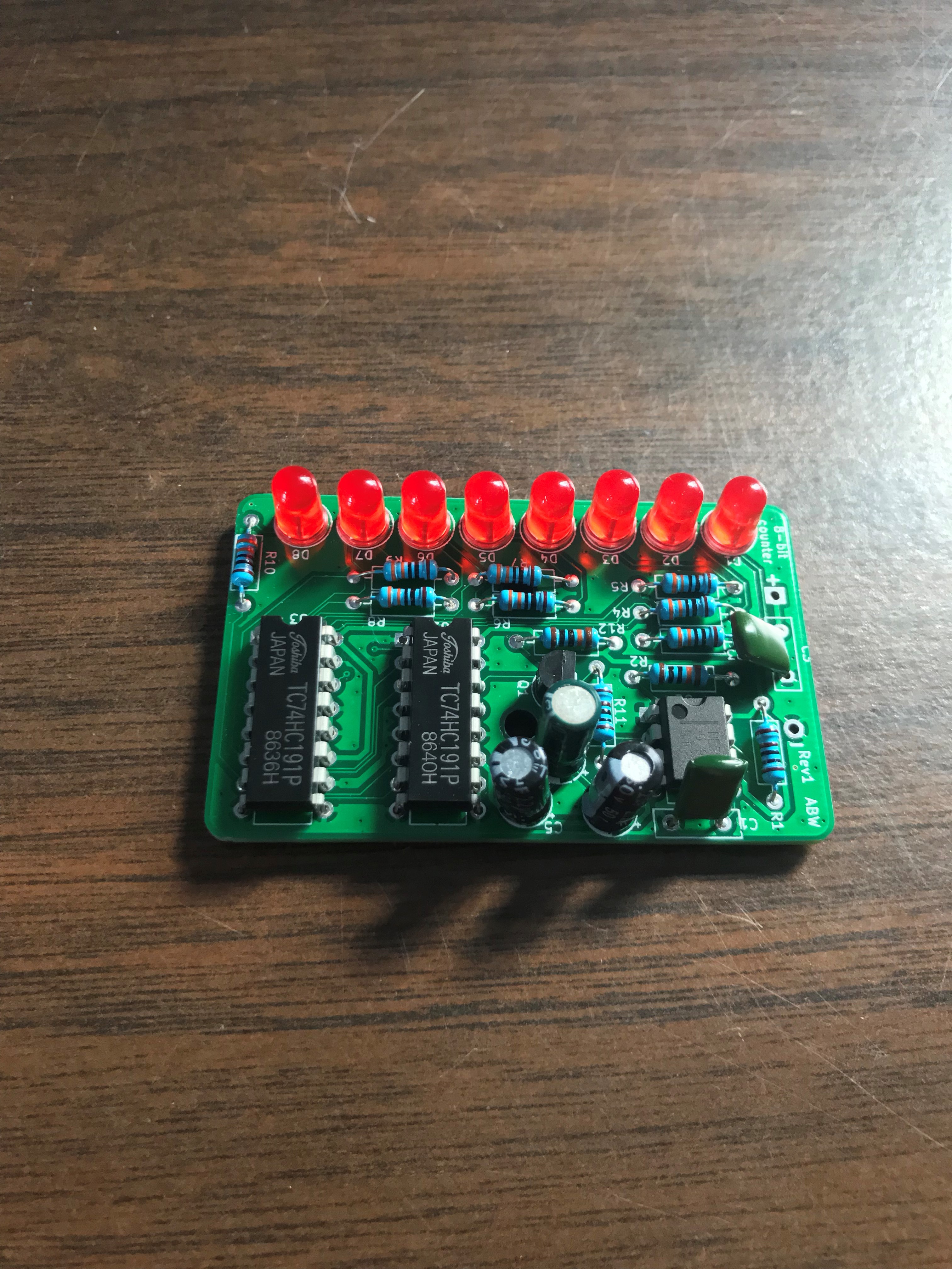
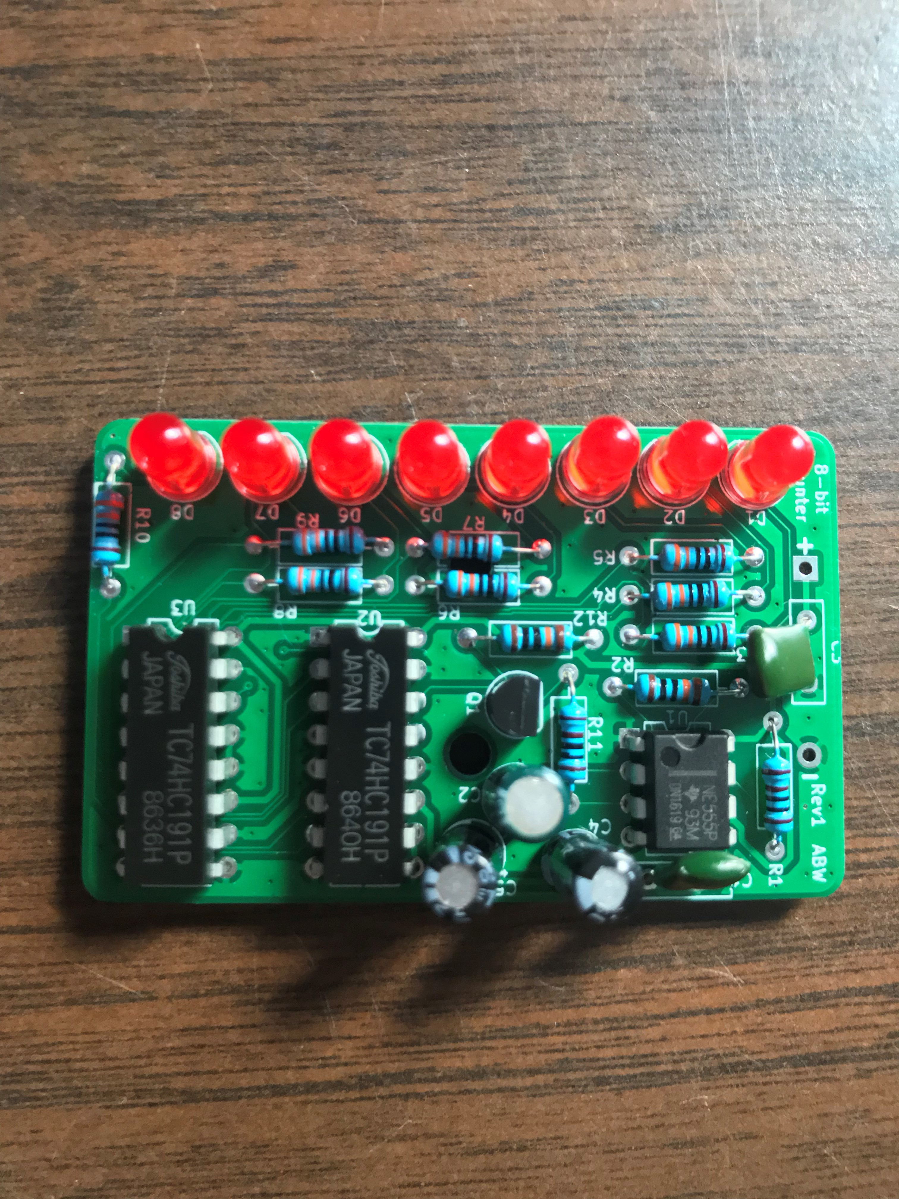
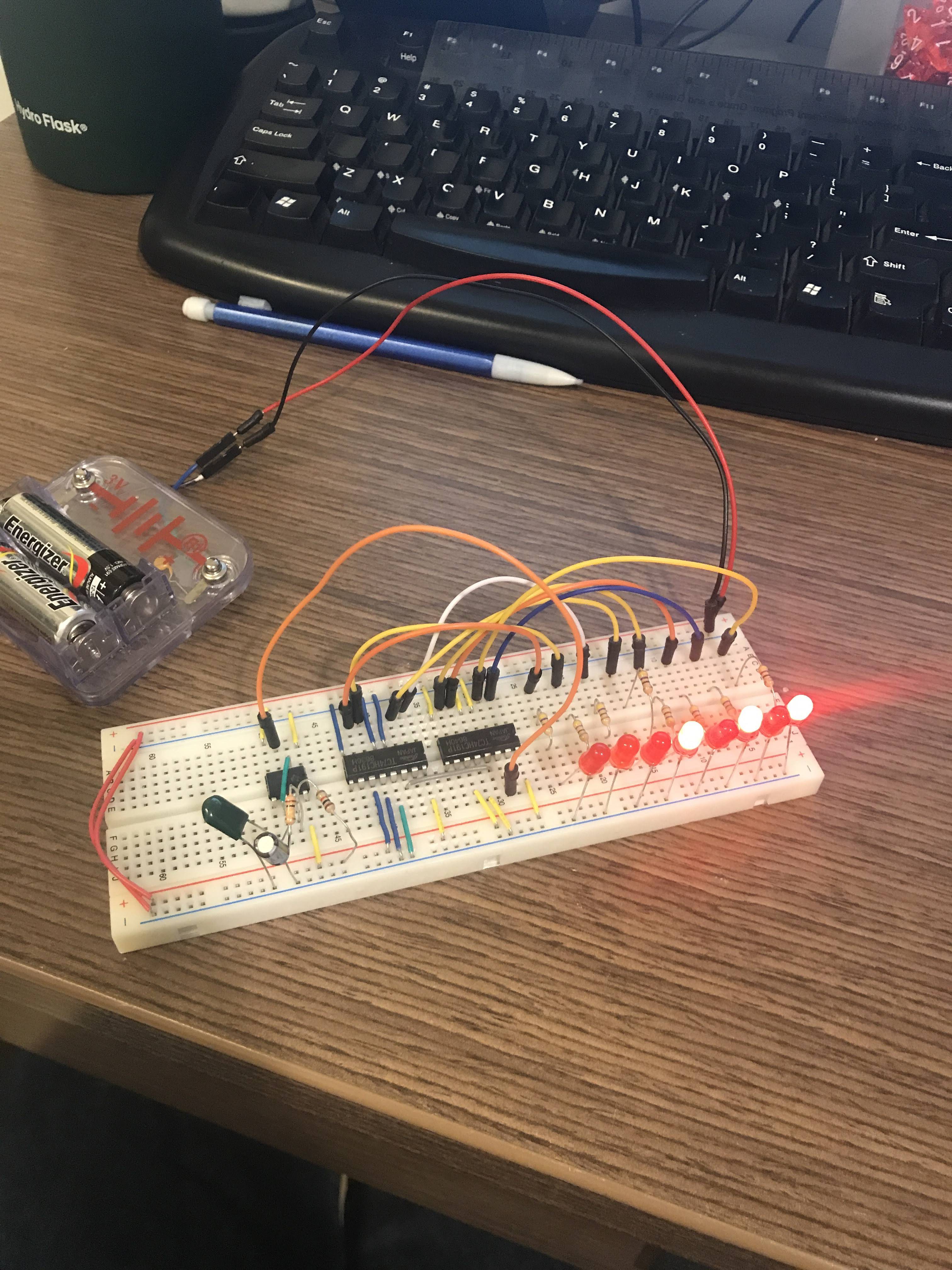
This project is a simple 8-bit counter using two 4-bit counter ICs. Powered by AA batteries and connected to LEDs, it visually displays counting up to 8-bits in binary. This works as a cool little visual display that can be displayed around the house or in a MakerSpace. It has no functional purpose, it is purely for display reasons only.

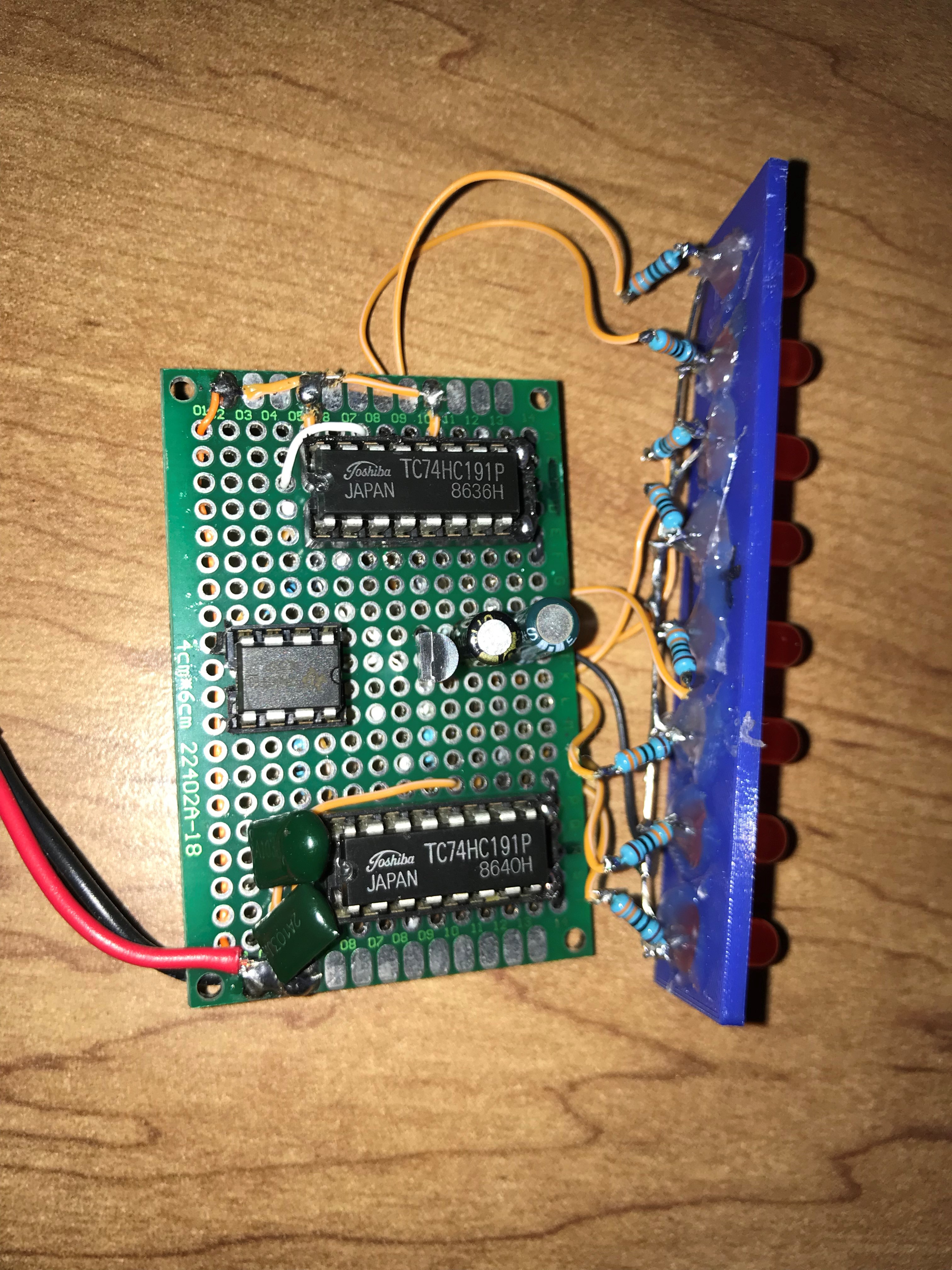
This project started as a found parts project after I found some 4-bit counters in school's student run makerspace. We had a whole wall of just 74xx ICs, which I had been going through, trying to figure out some of them did and find some 7-segment display decoders. These counters caught my eye. They are cascadable, so I could go up any number I wanted, as long as I had the LEDs for it.

After finding the datasheets (these ICs were old), I started bread-boarding a 4-bit counter with LEDs connected to the outputs. With that verified, I bread-boarded two counters cascaded, still using LEDs. 

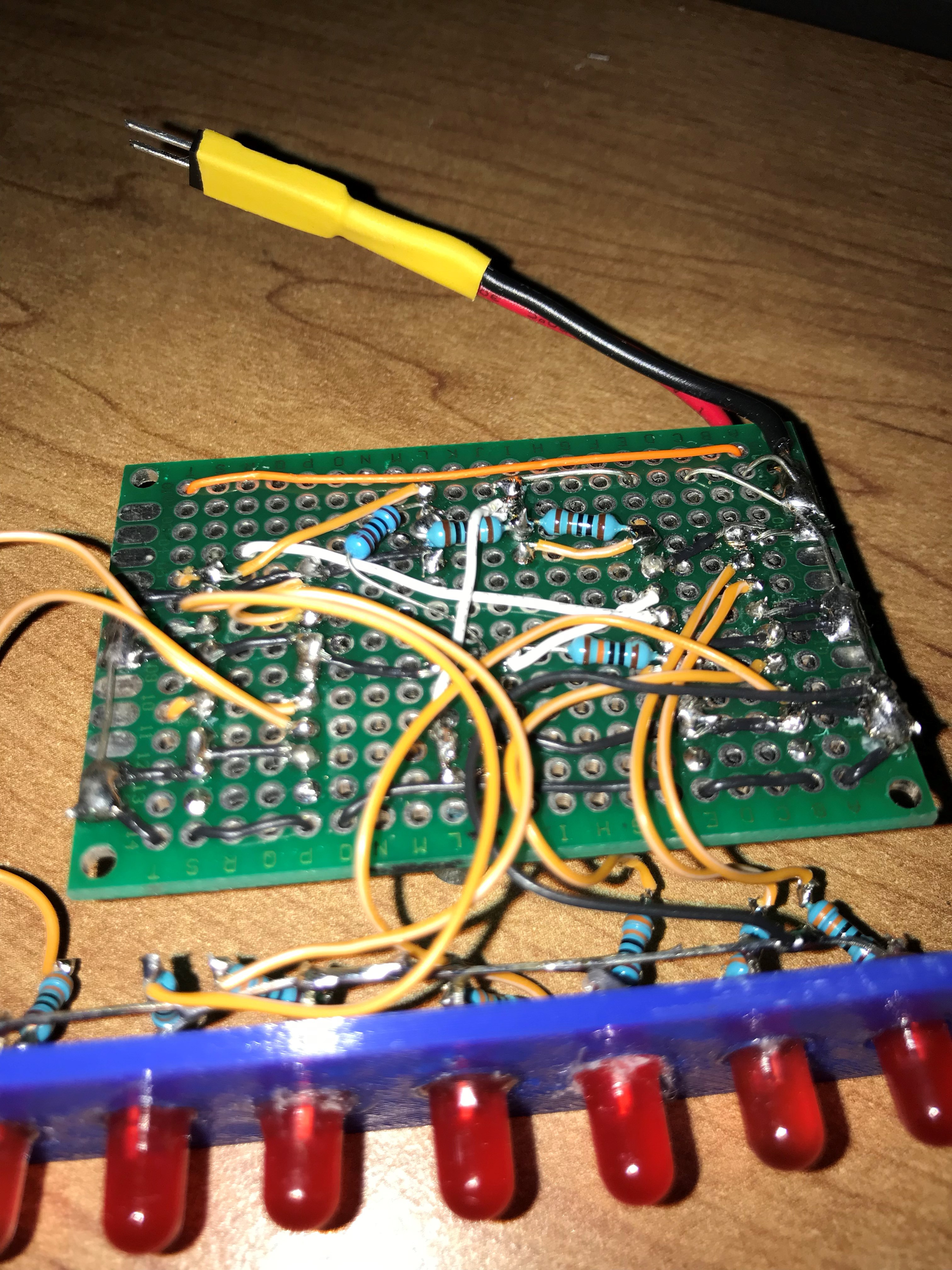
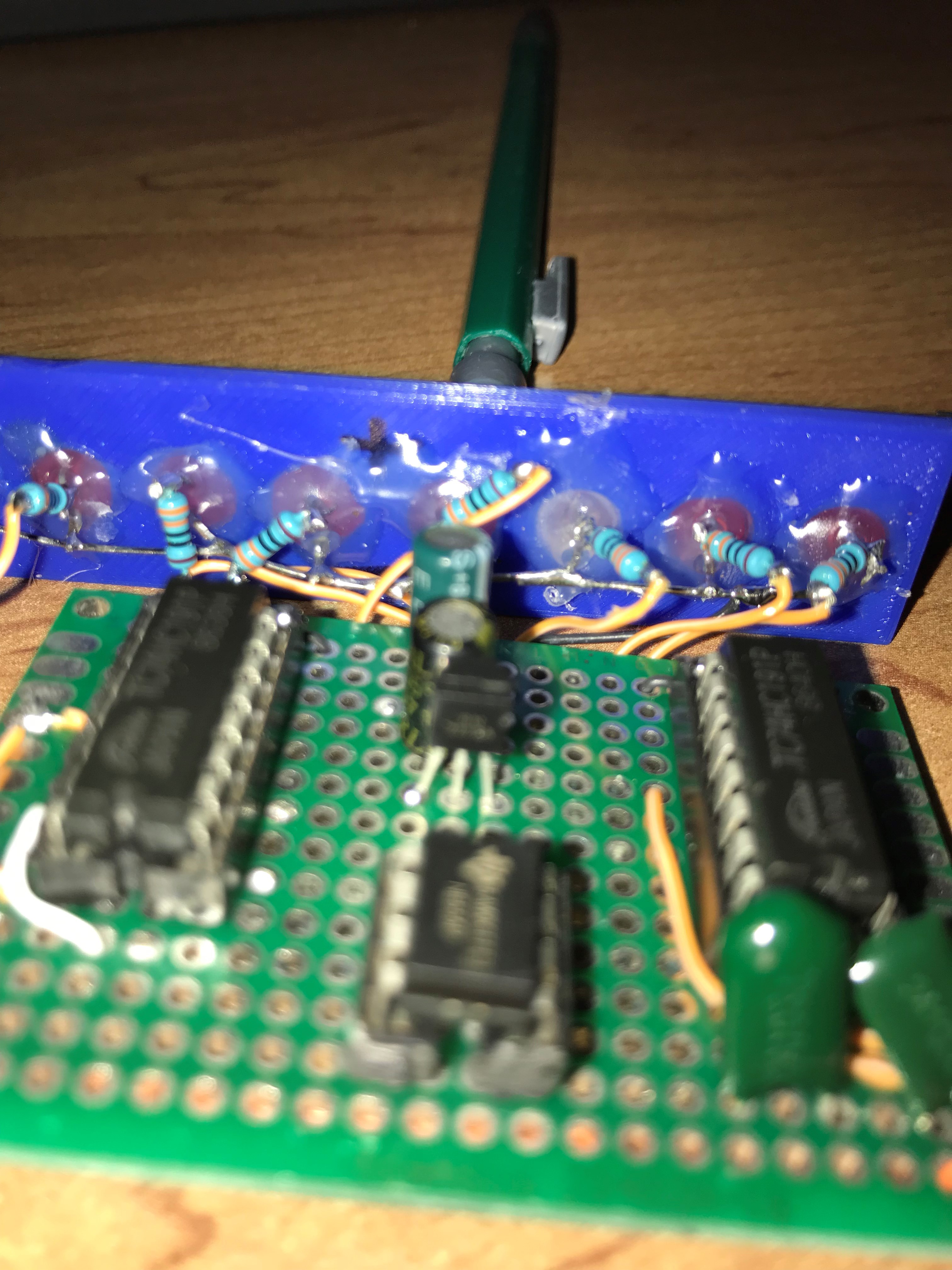
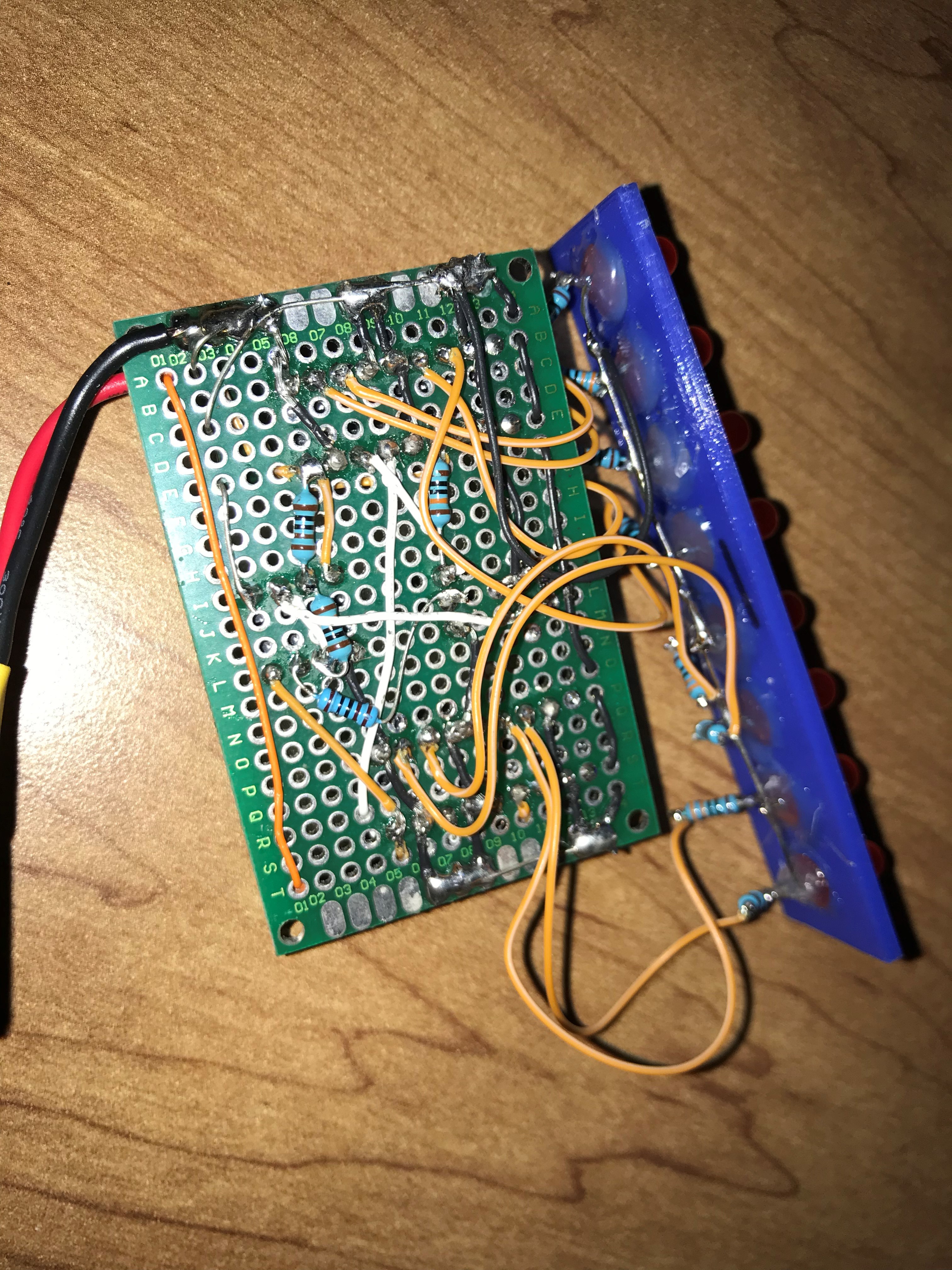
The next step for this project was to build a proto-board version using a 555 timer as a clock and 3D a cage for it. This version worked well, though the external battery pack was annoying and awkward.

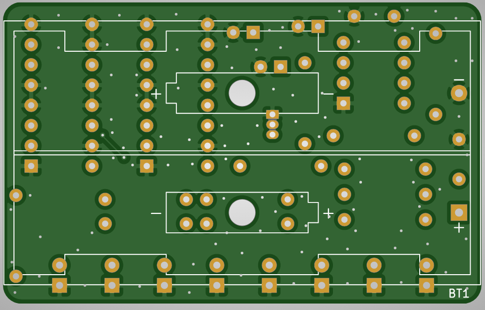
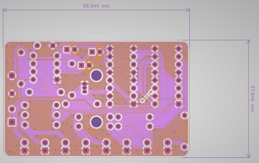
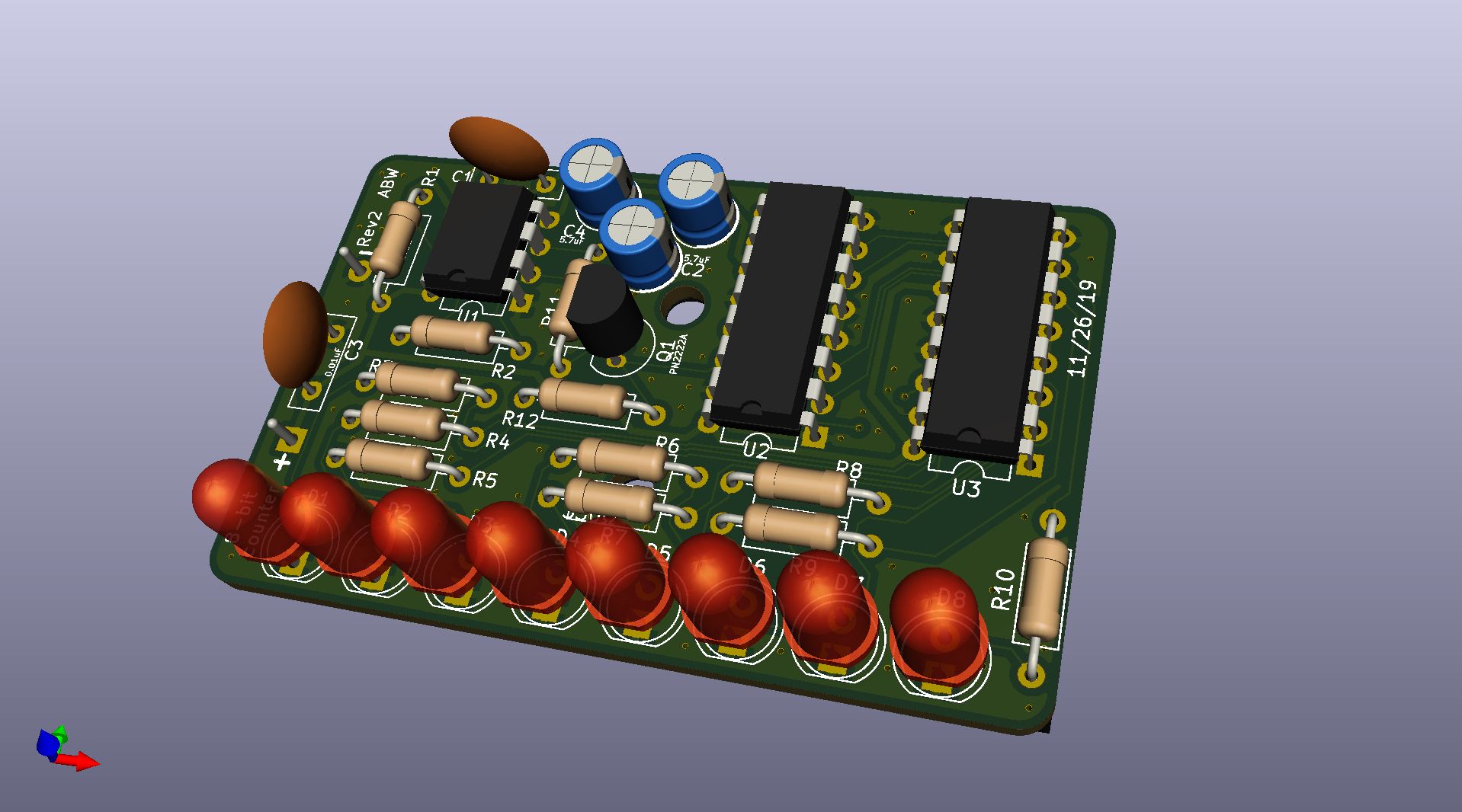
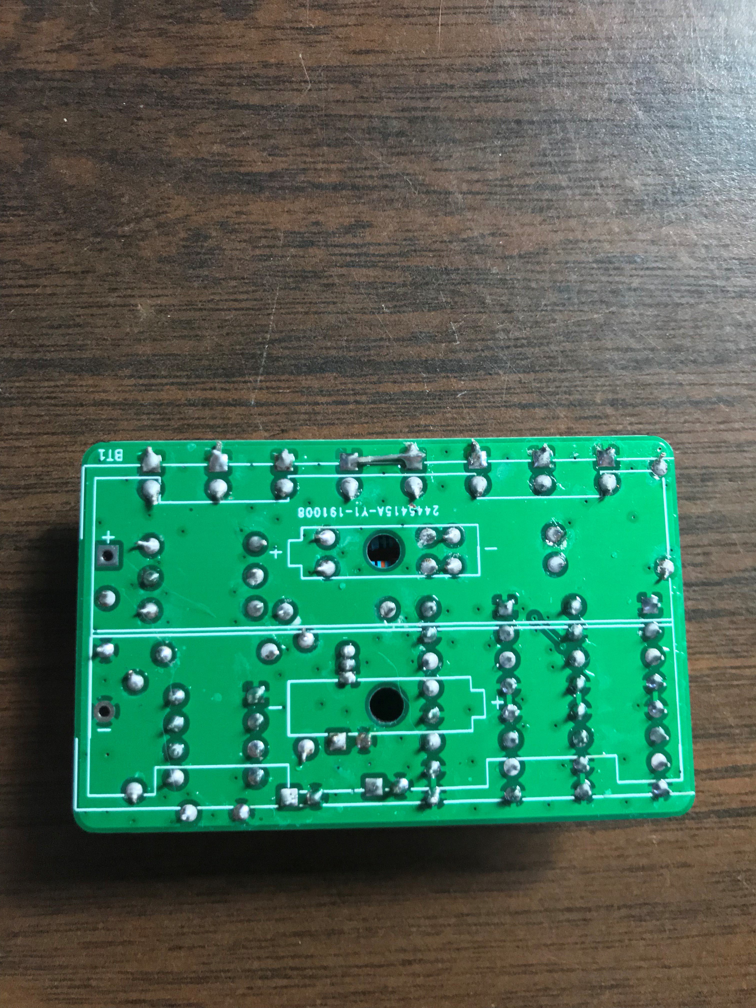
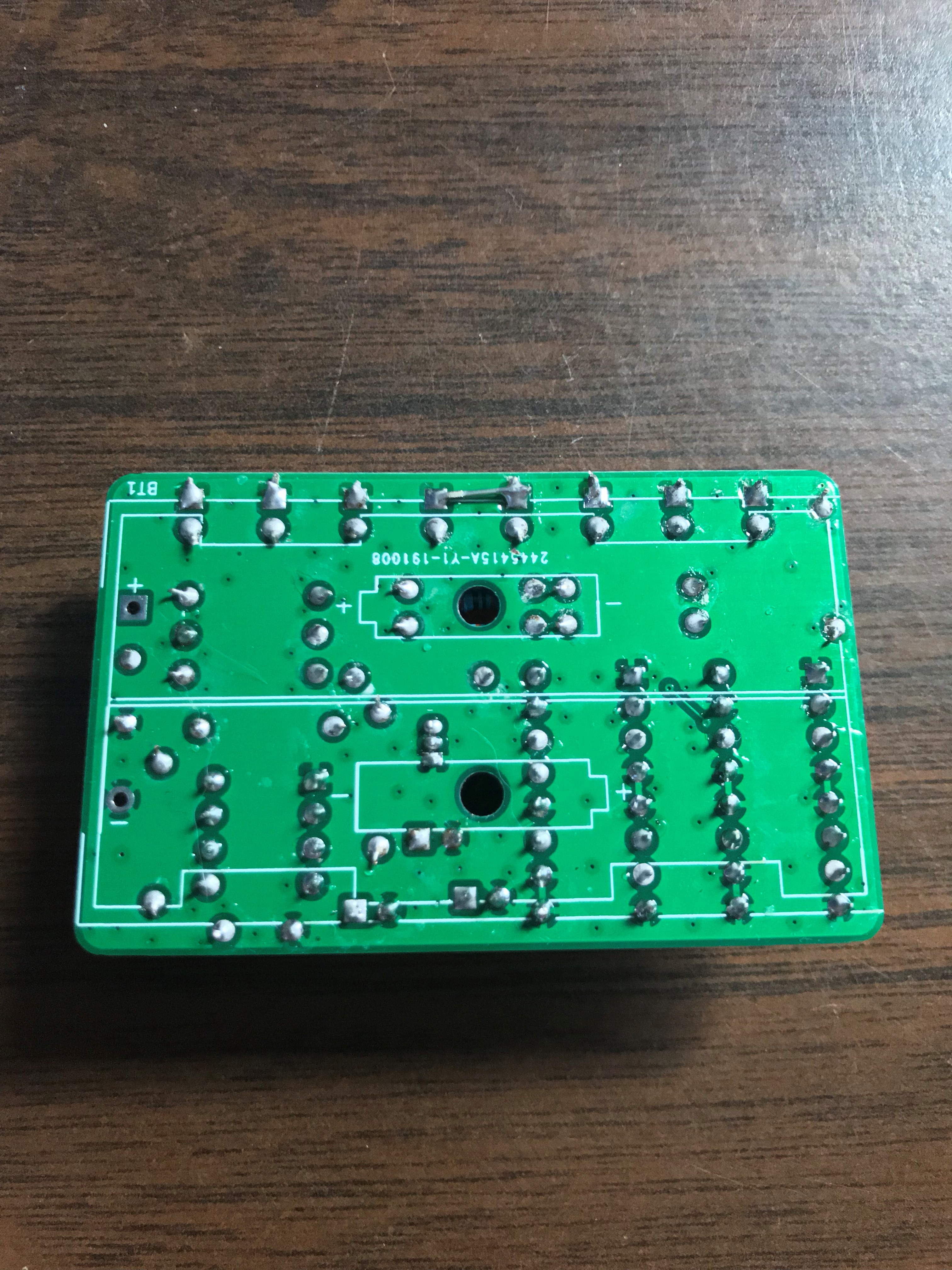
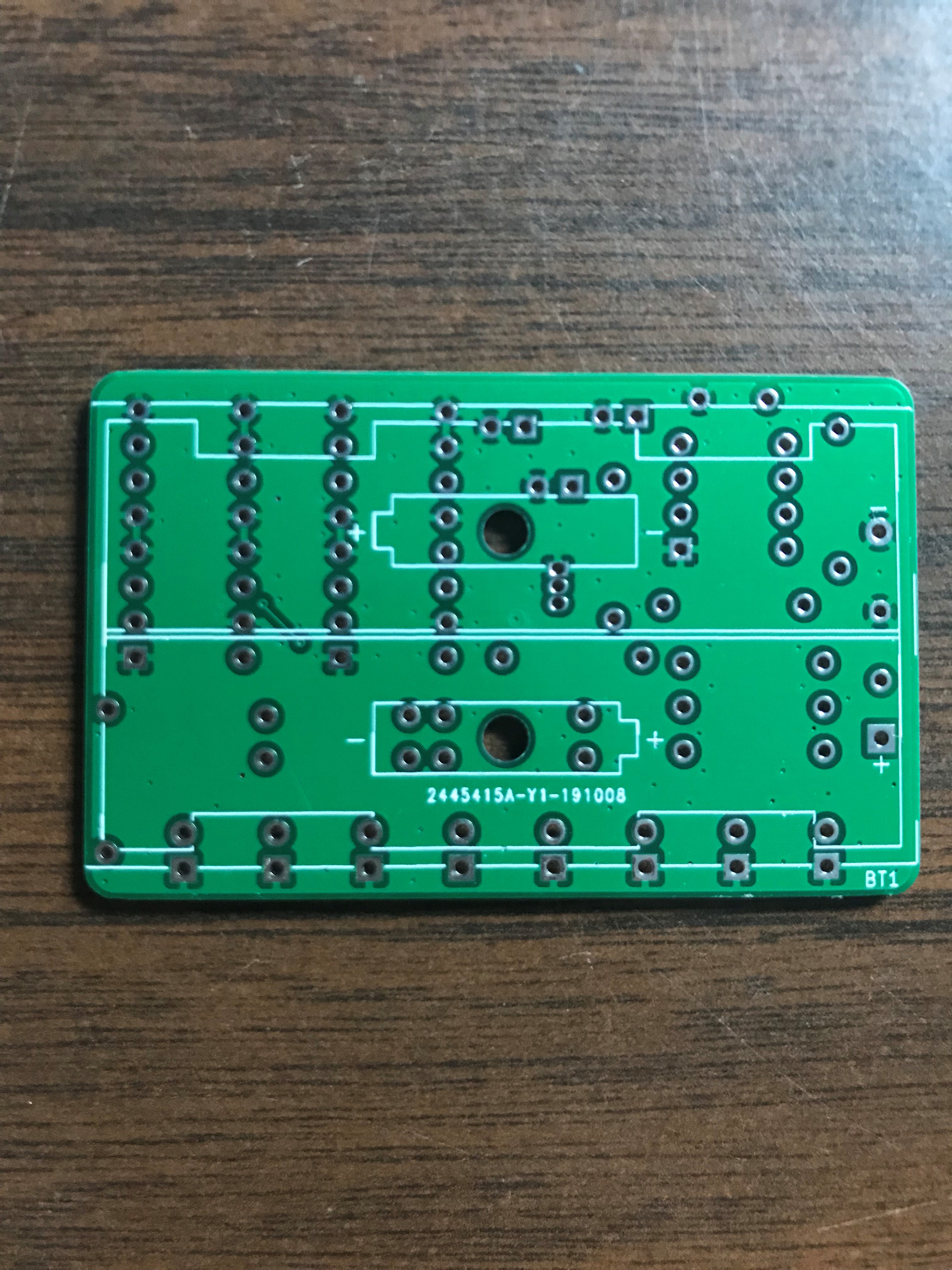
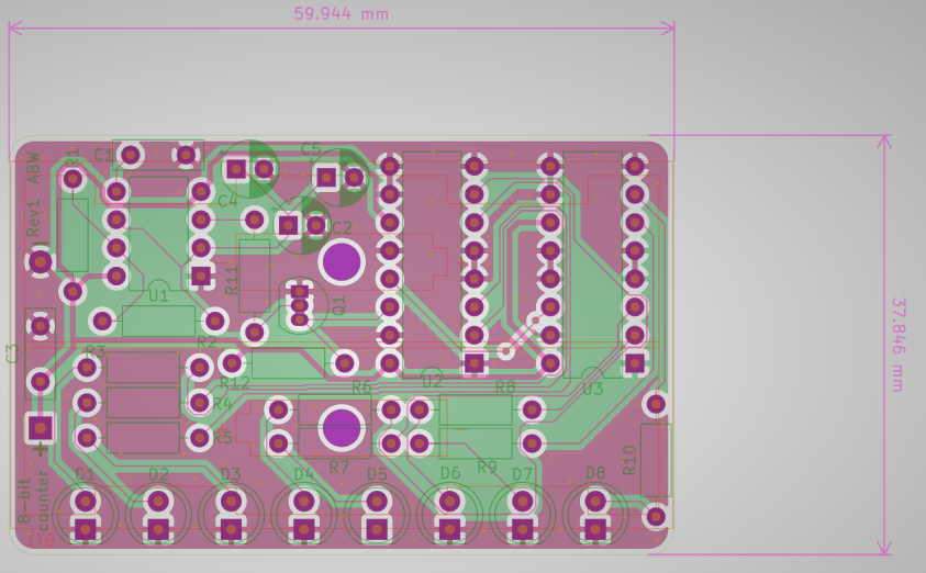
Enter the PCB. Based on the bread-board and proto-boarded versions, I designed a PCB to minimize the footprint.

Rev2.zip

PCB Rev2 zipped .gbr files

x-zip-compressed - 121.96 kB - 12/16/2019 at 15:44

Download

  • Rev2 PCB Designed

    sirmylesavery12/16/2019 at 15:39 0 comments

    After finding a couple errors with Rev1 of the PCB, I made a couple changes to the PCB design to fix them. Attached are some rendered and traceviews of Rev 2.

  • PCBs Populated

    sirmylesavery12/16/2019 at 15:30 0 comments

    Around Thanksgiving, 2019, I finally populated the PCBs. Attached some photos of the populated boards, with at least one of them powered.

    Some issues I've found: One of the LEDs cathodes was not connected to ground, which is a simple fix. Also add values to silkscreen, to make assembly easier.

  • PCBs arrived!

    sirmylesavery12/16/2019 at 15:26 0 comments

    At the end of October, 2019, the PCBs finally arrived! They look quite good. A couple silkscreen problems, but those were on the design end, not manufacturing end. Attached are a couple photos of the blank PCB.

  • PCB Revisions 1 Designed

    sirmylesavery12/16/2019 at 15:20 0 comments

    Back in October 2019, I finally got around to designing a PCB for the 8-bit counter. It uses the same components as the proto-boarded version, but in a small/more organized package. The design ended up being pretty simple. I used DIP packages, 5mm LEDs, and 1/2W resistors so that everything can be soldered easily by hand. No SMD components were used.

    Below are some photos of the PCB design.

  • Proto-board!

    sirmylesavery12/16/2019 at 15:12 0 comments

    Having verified the project with a bread-board, I decided the next step was to build a proto-board version. I think I did this at some point in February of 2019. Using some sockets for the DIP ICs in case I messed up the soldering, I soldered the parts to a proto-board. I also 3D printed a case for the proto-board (not pictured).  It's powered by two AA batteries (not pictured) which are connected via some jank connectors that can be connected backwards by accident.

    Below are some bad pictures of the proto-boarded version of the 8-bit counter. I will try to uploaded better/more photos once I get back to school where this is.

  • Bread-boarded Versions

    sirmylesavery12/16/2019 at 15:03 0 comments

    Back in December of 2018, I found some 4-bit counter ICs in my school's student run MakerSpace. I bread-boarded these, using LEDs to visualize the outputs. Initially I used an Arduino as a clock. Once I verified that, I used a 555 timer to generate the clock, removing the need for an MCU.

    Included are some images, which are limited in quantity and quality because I wasn't good about logging this project (as you can probably guess by the date of this post).

View all 6 project logs

Enjoy this project?

Share

Discussions

Ken Yap wrote 12/16/2019 at 19:05 point

Sure, why not, good practice in design and assembly. BTW, they are called datasheets, not spreadsheets.

  Are you sure? yes | no

Thomas wrote 12/16/2019 at 19:49 point

This reminds me of my early youth: a TTL ripple counter on my desk and FeCl3 stains everywhere else.

  Are you sure? yes | no

Ken Yap wrote 12/16/2019 at 20:06 point

🐱 My mother was not enamoured of my darkroom phase either. Hypo fixer solution did bad things to towels.

  Are you sure? yes | no

Thomas wrote 12/16/2019 at 20:33 point

Ah, don't remind me of that. The experiments with potassium permanganate and glycerine also caused some trouble.

  Are you sure? yes | no

sirmylesavery wrote 12/16/2019 at 20:42 point

Good catch, that's what I get for not proof-reading my writing!

  Are you sure? yes | no

Similar Projects

Does this project spark your interest?

Become a member to follow this project and never miss any updates