 Max.K
Max.K
0%
0%
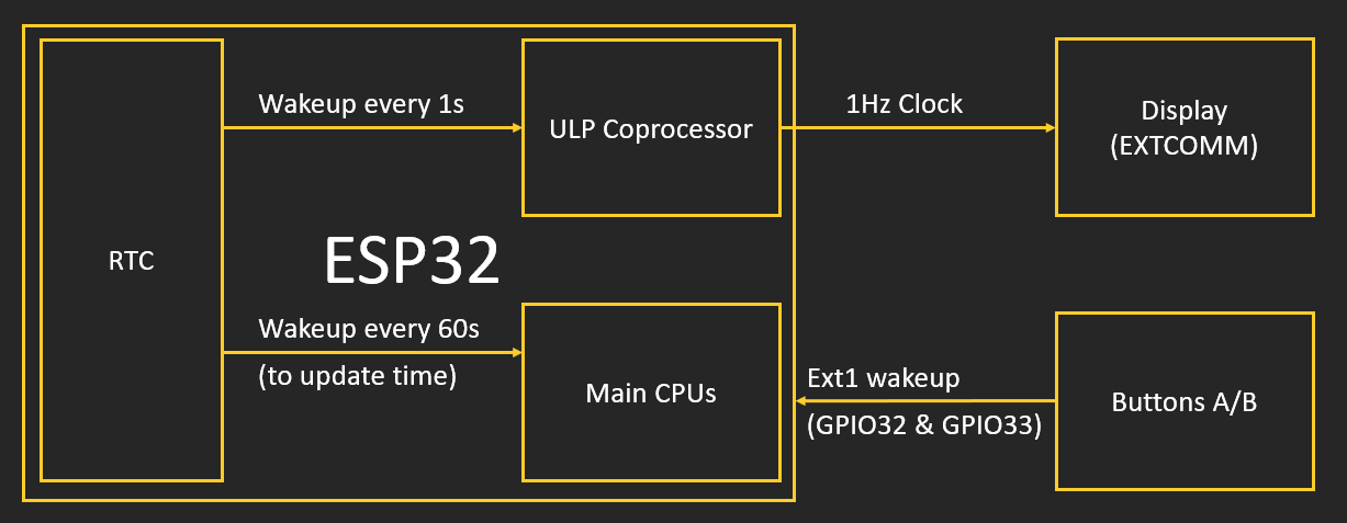
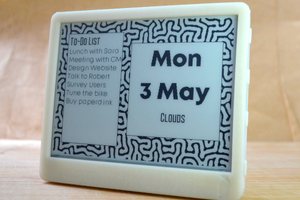
Low Power ESP32 Handheld
Pocket sized ESP32 display board with 180µW Always On Display and Gyro Controls
Become a Hackaday.io member
Already have an account? Log in.
Just one more thing
To make the experience fit your profile, pick a username and tell us what interests you.
Pick an awesome username
hackaday.io/
Your profile's URL: hackaday.io/username. Max 25 alphanumeric characters.
Pick a few interests
Projects that share your interests
People that share your interests


 Rohit Gujarathi
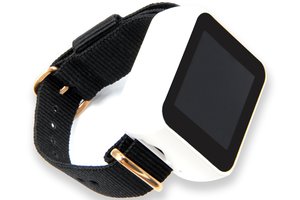
 LILYGO
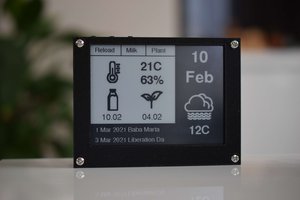
 Boris Shabanov
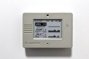
 Manuel Alfonso
Heyya, looking at making one of these and the only component I can't find is a MCP1640CT-I/CHY
Any suggestions? I'm mainly a Software developer + project looks fun af