Overview, Configuration and Operation
The clock consists of an LPC11U24, DS1302, ULN2803 and white LEDs.
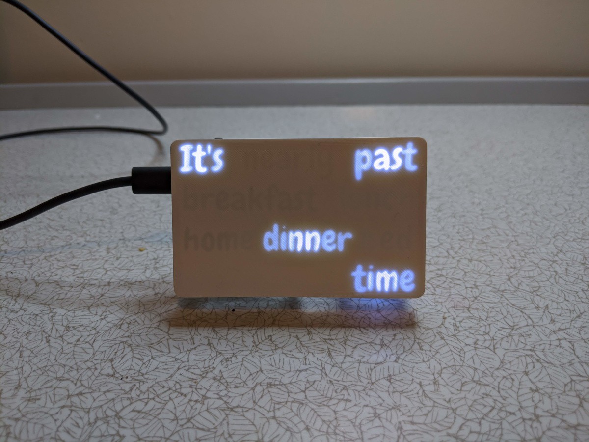
There's a push button which can be used to turn the display off/on. If it's turned off, it will automatically come back on at "nearly breakfast time" the following day. Holding down the button enters "demo mode" where it cycles through all the times.
The clock configuration consists of a number of parameters:
- The time, obviously. Stored into the RTC chip with a battery backup
- A time for each "meal". The defaults match my usual (aspirational) schedule:
- Breakfast - 08:00
- Lunch - 12:20
- Home - 17:30
- Dinner - 19:00
- Bed - 22:00
- A time for "sleep" at which point the display turns off until the next morning
- A time period before each "meal" which counts as "Nearly" (default 15 minutes)
- A time period after each meal which counts as "Past" (default 15 minutes)
- A display brightness
All of the parameters except for the time are stored into the EEPROM on the microcontroller. The RTC chip does have battery-backed SRAM for general purpose storage, but I figured EEPROM made more sense for these mostly static parameters.
All configuration is done over USB serial with a simple set of text commands:
# Set/get the time
SET TIME 2019-12-30-17:03:00
GET TIME

# Set/get a specific "meal" time
SET {BREAKFAST,LUNCH,HOME,DINNER,BED,SLEEP} 01:23
GET {BREAKFAST,LUNCH,HOME,DINNER,BED,SLEEP}

# Set/get the nearly/past times
SET {NEARLY,PAST} 00:15
GET {NEARLY,PAST}

# Set/get display brightness
SET BRIGHTNESS 0xFFFF
GET BRIGHTNESS

# Reboot
RESET
The history of the project is quite long and meandering...
Iteration 1 - January 2014
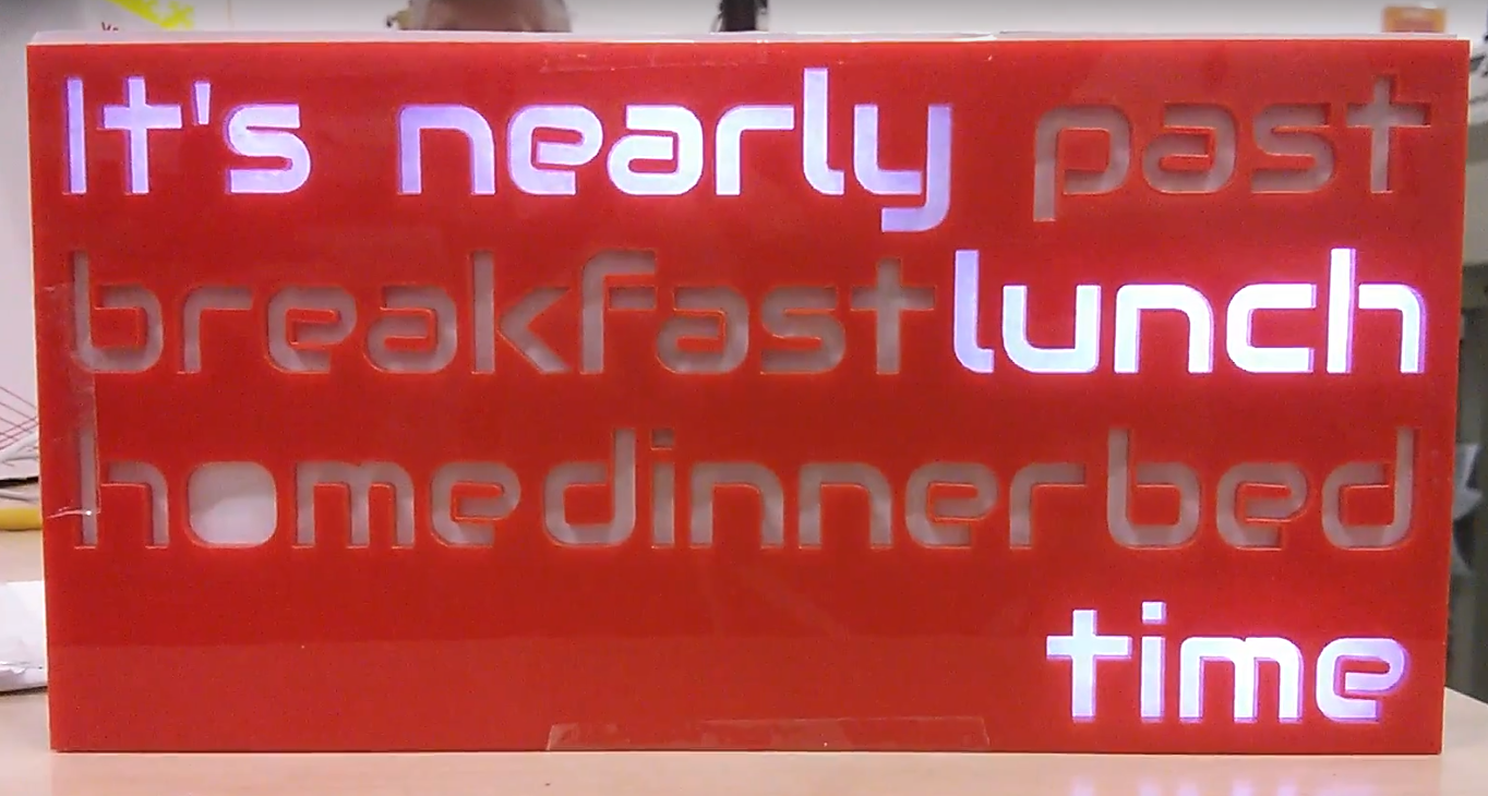
The first attempt was all laser-cut in 3 mm acrylic, with the words cut into the front panel, a set of light-blocking dividers and a piece of white polystyrene as a diffuser.
At the end of 2012, TI had run a giveaway for their new line of Arm MCUs, and I had ordered one, blinked the on-board LED and never touched it since. I figured it had a built-in RTC and lots of I/O so it might make a good choice for the clock. I dusted it off and wrote just enough code to scroll through all the sentences.
At some point before I sorted out actual time-keeping, I got the idea that I'd like to make more than one clock to give to people as gifts, and so the TI Launchpad suddenly looked like a terrible idea as it was hard to get. Also, I never really got on with it, I don't remember the specifics, but the documentation and libraries weren't very good as far as I remember.
Iteration 2 - May 2014
I switched to trying an Attiny2313 instead, because I had a bunch of them in my parts box already.
The Attiny doesn't have any RTC hardware, so I needed a way to get the time. I like the idea of users not having to worry about setting it, so I ordered a 60 kHz radio time receiver module.
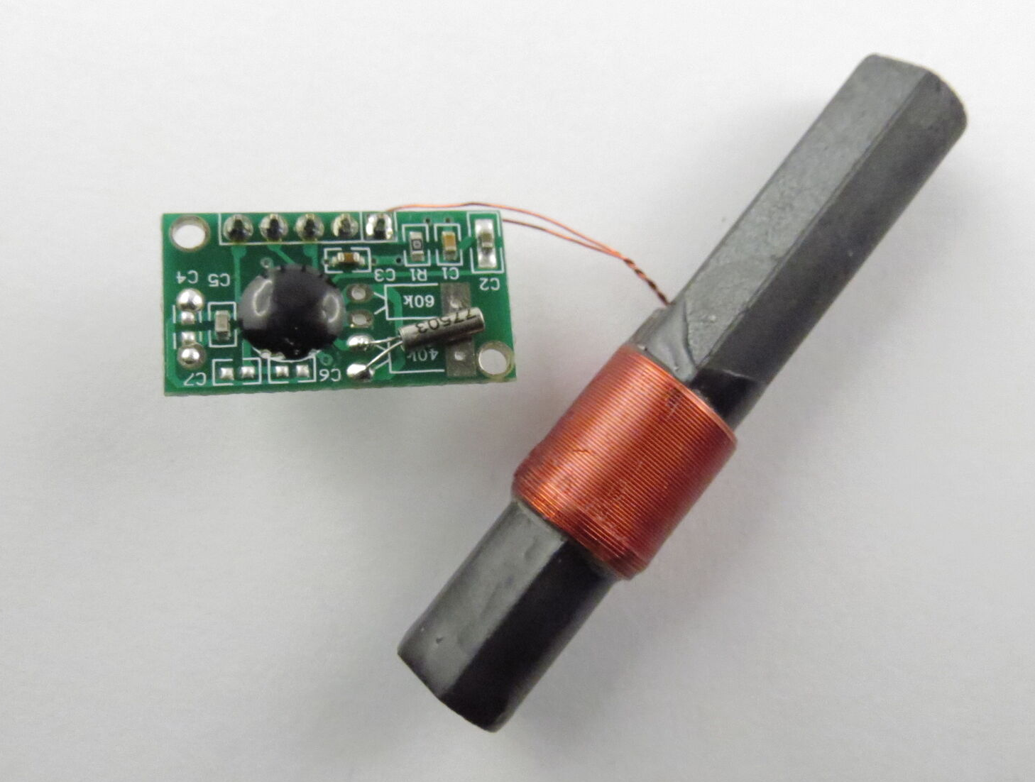
When I hooked up the receiver, it really didn't work well. The signal was too small, and the PWM for the LEDs was introducing a lot of noise. I spent a little time trying to fix that, but analogue electronics was never my strength and I got bored pretty quickly.
Iteration 3 - August 2014
So, I shelved the idea of using the MSF receiver, and ordered a plain boring DS1302 RTC module.
This is a real-time-clock with battery backup, so users would have to set the time, but hopefully only once (...each time the clocks change, because we have daylight savings time here).
That was dead simple to set up, but in the process I ran into the 2kB flash size limit of the Attiny2313.
Around this time, DirtyPCBs hit the news sites. I'd etched a couple of boards myself before with toner transfer, but never done anything with "small" SMD components, so I figured why not design and order a board with an Arm core for the clock?
Iteration 4 - January 2015
I settled on using the NXP LPC11U24 chip for my board. It's Cortex M0-based and has a USB bootloader in ROM which lets you flash code via USB...
Read more »
 jens.andree
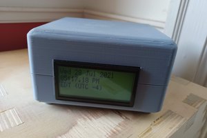
 zaphod
 Jan
Jan
 Warren Janssens