 lion mclionhead
Lions long dreamed of being able to capture 8 channels of analog & write them to a file. Analog would be better than just a logic analyzer. Kind of like the early days when lions used a sound card as an oscilloscope, but now with DC coupling.
Let's get 1 thing clear. Using a modern microcontroller as a logic analyzer is a terrible idea. The best logic analyzer from spare parts was the 1990's parallel port. Those could sample over 3Mhz. The mane problem with parallel ports was they only did 5V digital. Modern 2V logic wouldn't turn them on.
Then of course, the GPIO's on a raspberri pi can go a lot faster than a microcontroller, but still only in digital mode.
After years of contemplating, there was finally a need for a 6 channel logic analyzer with the analog mode envisioned. The STM32 could sample analog at 1Mhz & its USB driver should do 8 Megabits, so what could possibly go wrong?
The lion kingdom feels accomplished for making this 8 channel ADC from an ancient STM32 Discovery board, because it used the official STLink programmer instead of a hack. Helas, still hacked the development environment on Linux instead of using the official IDE. These boards are amazingly still being sold.
What a buster to get USB & all the clocks working on the STM32Discovery. The 1st problem was the USB connector goes to the full speed core instead of the high speed core while all the projects on custom boards used the high speed core. The 2nd problem was the board has an external 8Mhz oscillator while custom boards used the internal 16Mhz oscillator. The clocks had to be reconfigured, but this problem was only manifested as USB crashing, rather than anything obviously related to clockspeeds.
The mane focus of such a project is just trying to get as much speed out of an underrated microcontroller as possible. There are many tricks not present in high level programming languages.
To improve the sampling, it was overclocked to 240Mhz instead of its rated 168Mhz. The trick here is picking multiplier values so SystemCoreClock goes to 240Mhz while still generating a 24Mhz USB clock.
Helas, the sample rate was abysmal. USB throughput limited the 8 channel analog sampling to 8000000/8/8 or 125000 Hz but the ADCs were also limited. Using a polling loop to trigger 2 ADC's, the ADCs could each go no faster than 500Khz. Split between 8 channels, that gave 125000Hz per channel. The polling speed was the limiting factor. Past experiments showed polling was faster than DMA on the STM32's because they couldn't schedule the AHB bus as optimally as a lion programming deterministic instructions.
The digital mode was similarly limited by USB throughput as well as the microcontroller to 1 megsample/second. It instantaneously varied between 2.6Mhz & 610khz because USB transfers slowed down memory accesses. The fastest signal it could reliably probe while streaming over USB was 300khz. If it just captured to RAM, it could get only around 176 ksamples. Then of course, the key step is using 8 pins that can be read in a single register read.
Using the common core memory made no difference. The USB driver could actually read from it, but it was just as slow as mane memory.
The way to view captured waveforms was of course an audio editor. Set the timeline samplerate to 4x the waveform capture rate & it shows 1 sample every 4 pixels.
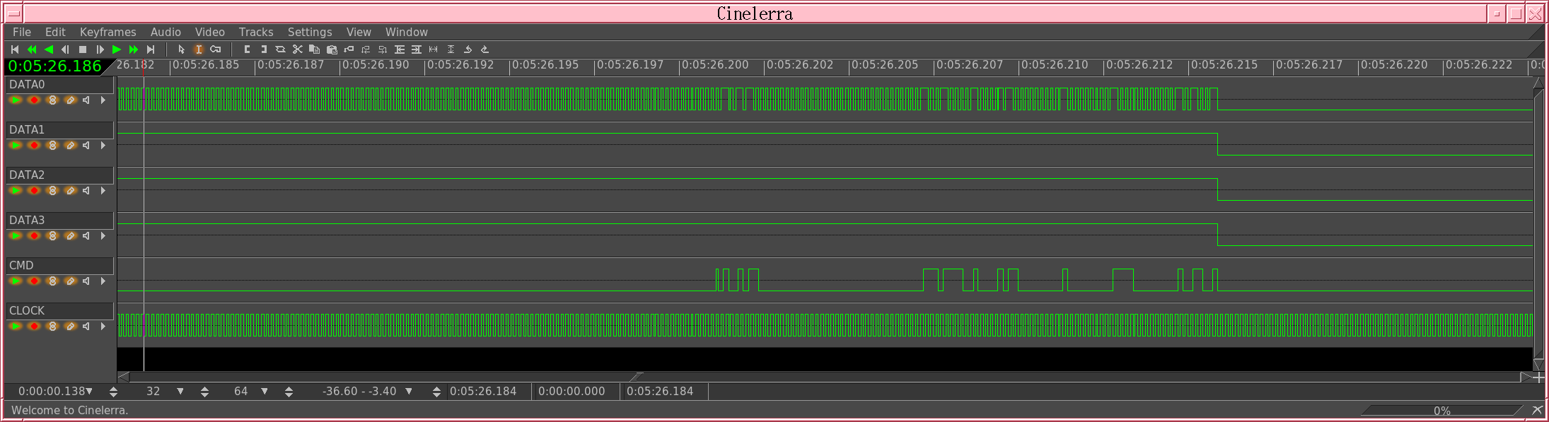
The 1st digital capture of a certain bus was confusing. DATA0 had the same signal as CLOCK, or did it.

In analog mode, the sample rate was drastically lower but it was clear that the data lines were floating, sympathetically oscillating with the CLOCK line. DATA0 was near the threshold of the digital mode while the others were above the threshold. DATA0 would easily pick up the clock signal. Also in analog mode,...
Read more »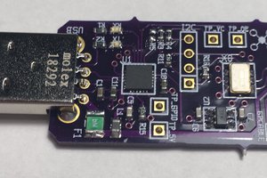
 Carbon
 Aleksa
 Gee Bartlett
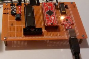
 DL101
DL101