Circuit Diagram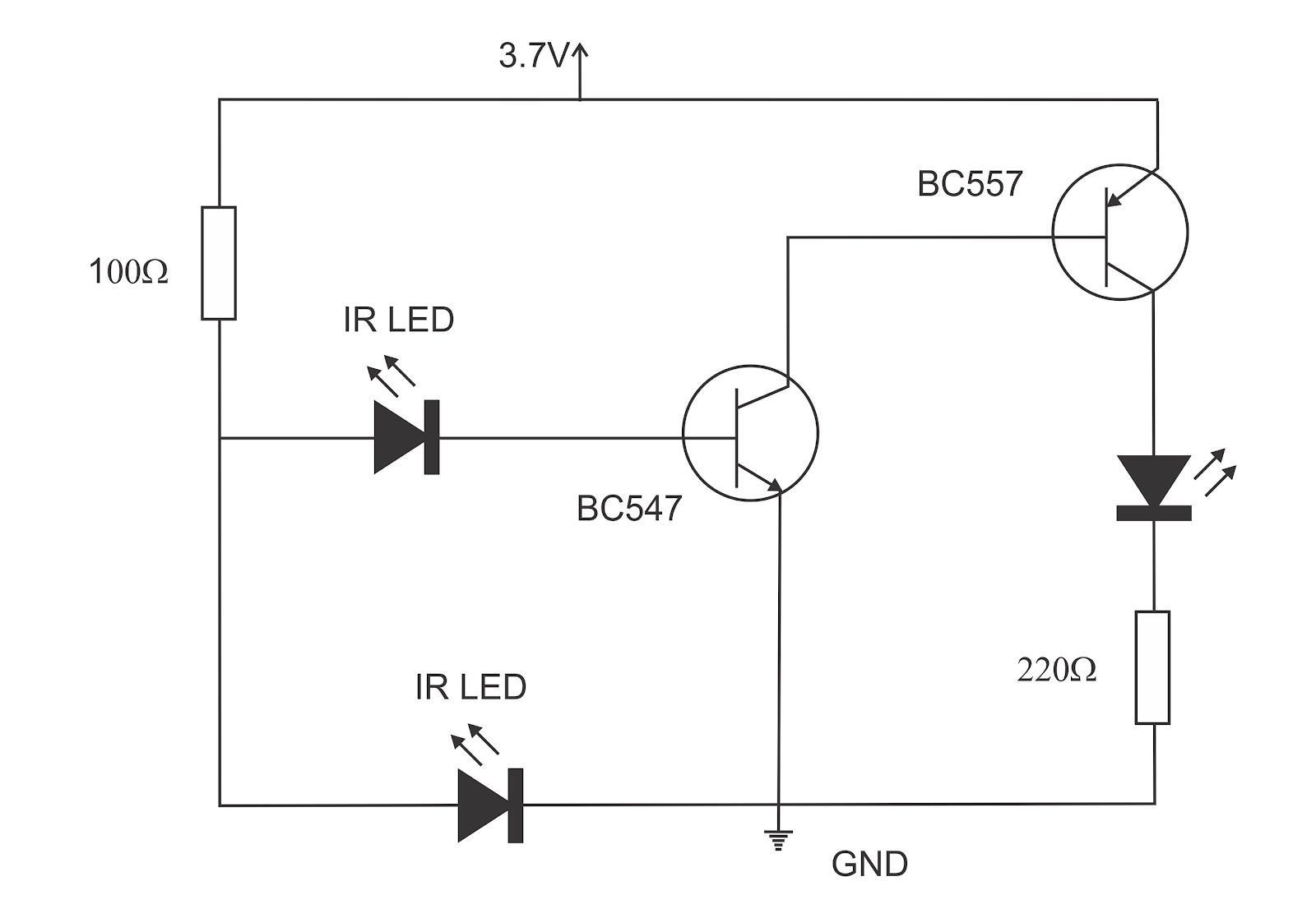
Steps to follow:
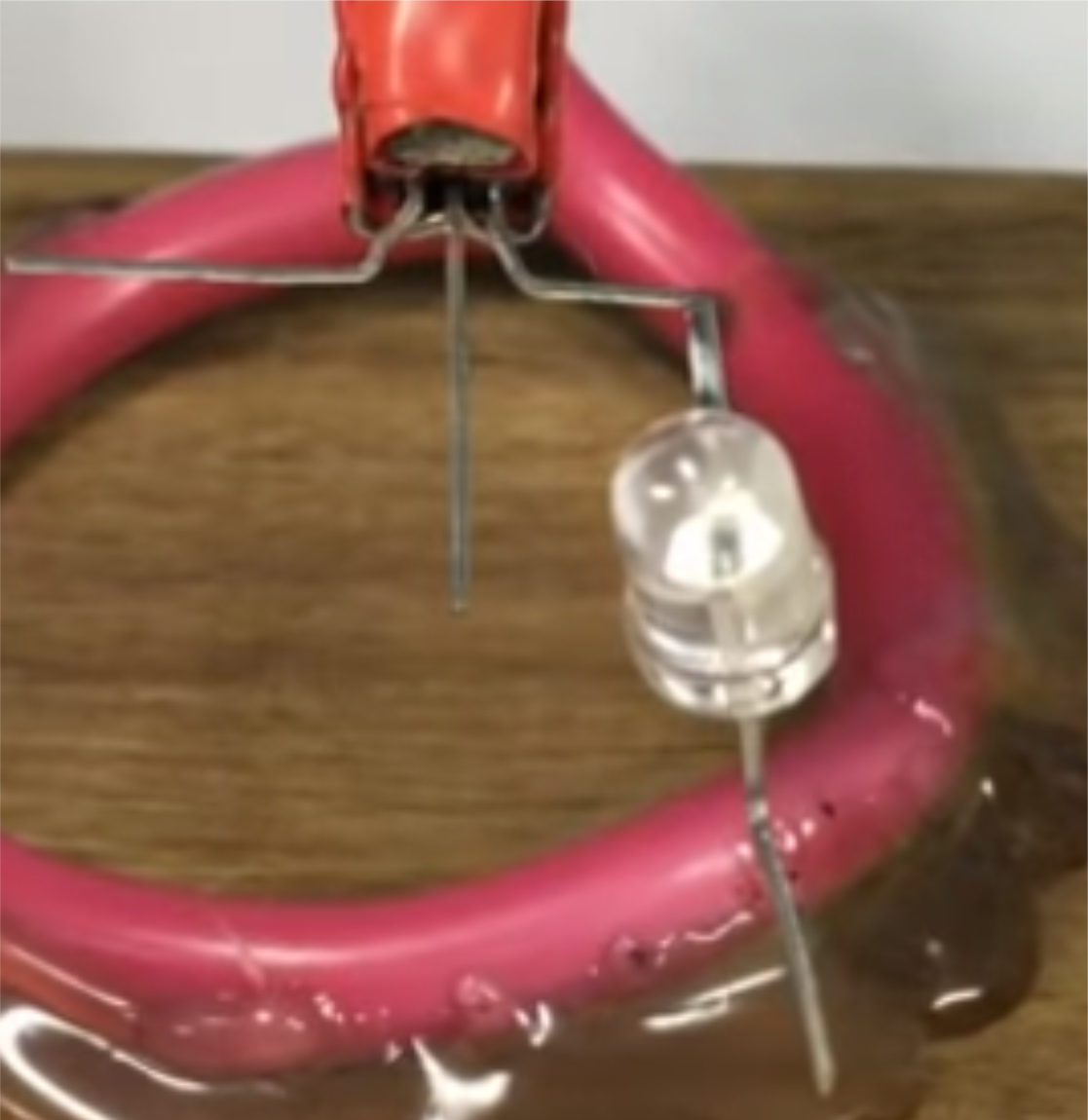
Step 1: Arrange the components.
Step 2: Solder one IR LED to the emitter pin of the BC547 transistor.
 Step 3: Solder the other IR LED to the base pin of the BC547 transistor.
 Step 4: Solder 100Ω resistor to the remaining pins of the IR LEDs.
 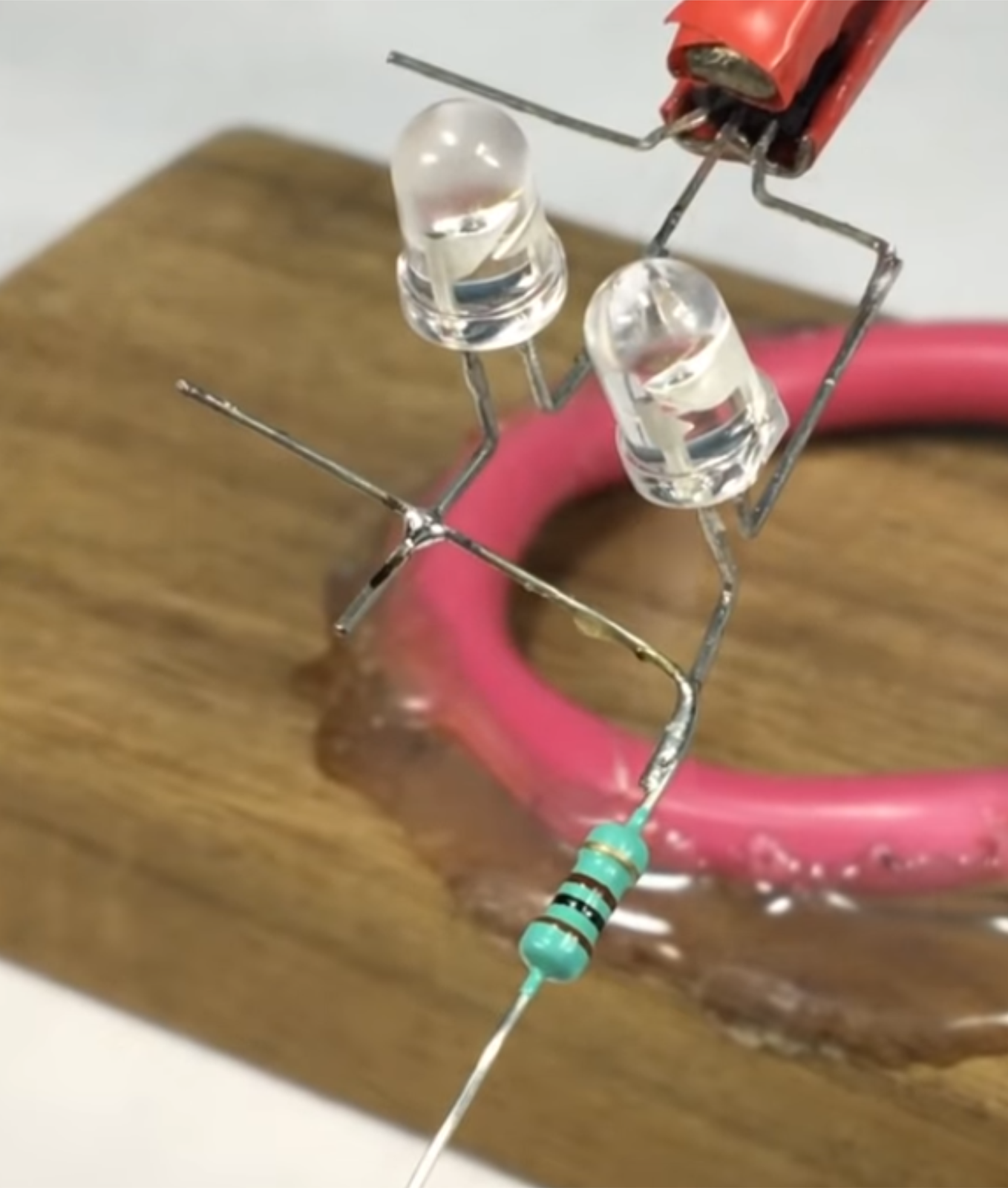 Step 5: Solder the base pin of the BC557 transistor to the collector pin of the BC547 transistor.
 Step 6: Solder the normal LED as shown in the circuit diagram.
 Step 7: Solder the 220Ω resistor as shown in the circuit diagram.
 Step 8: The circuit is now ready to connect to power as shown in the circuit diagram in order to test it.
 How it works:
When the detector IR LED is detected, the reflected IR light from the object will trigger a small current that will flow through the detector IR LED. This will trigger the BC547 transistor and it will also cause the BC557 to trigger, hence the LED will turn on.
Conclusion
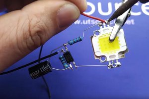
You can use this circuit to build various projects such as automatic lamps which turns on when a person comes near to the light.
Enjoy! Contact us for any inquiries!

 Electroniclovers123
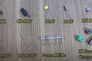
 UTSOURCE
 Hulk
Hulk
 Alexandra Covor
Check the schematics. I think the top-left IR LED should be put backwards, as it is shown in the pictures at step #3 and #4