 Chris Combs
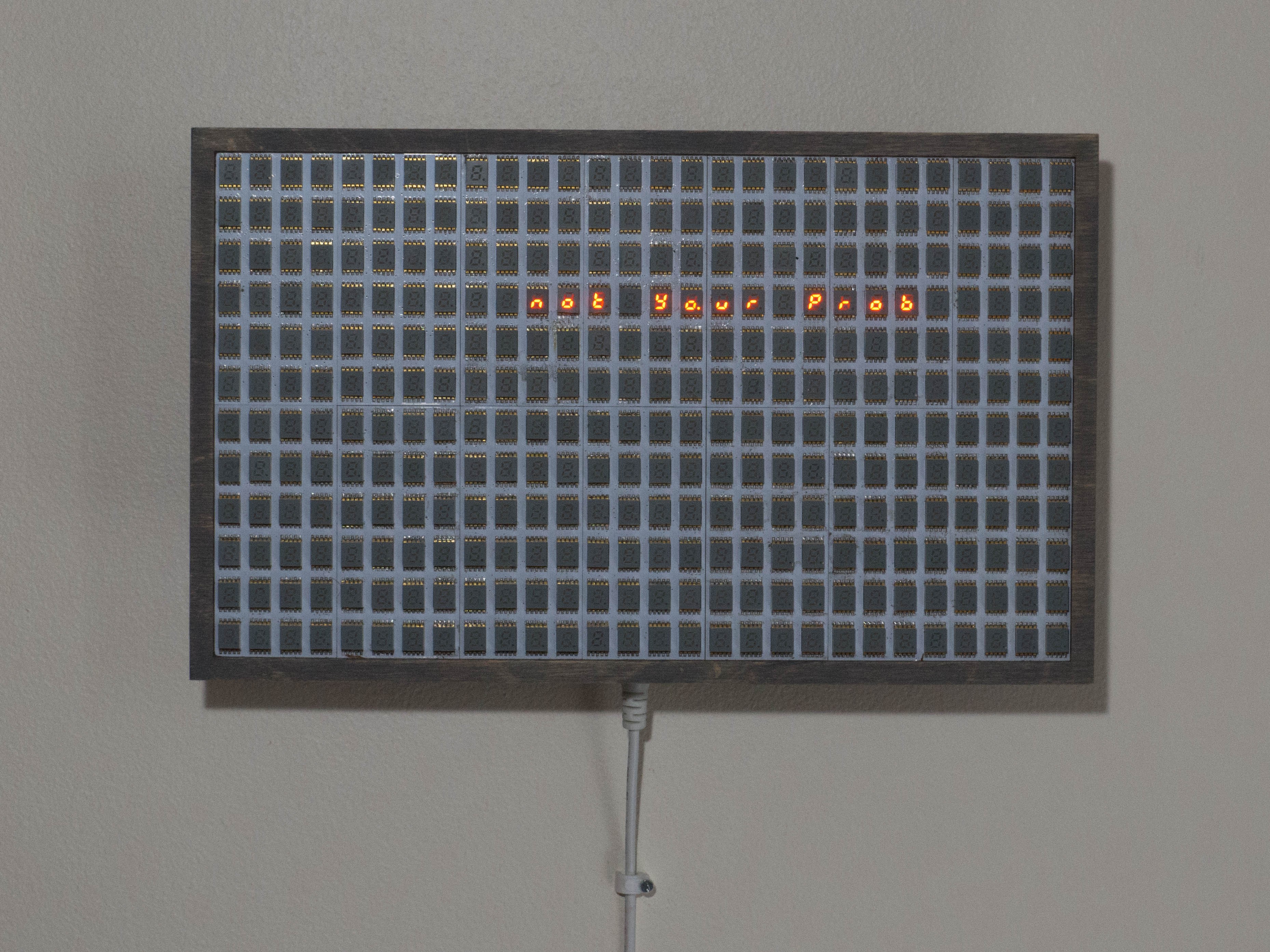
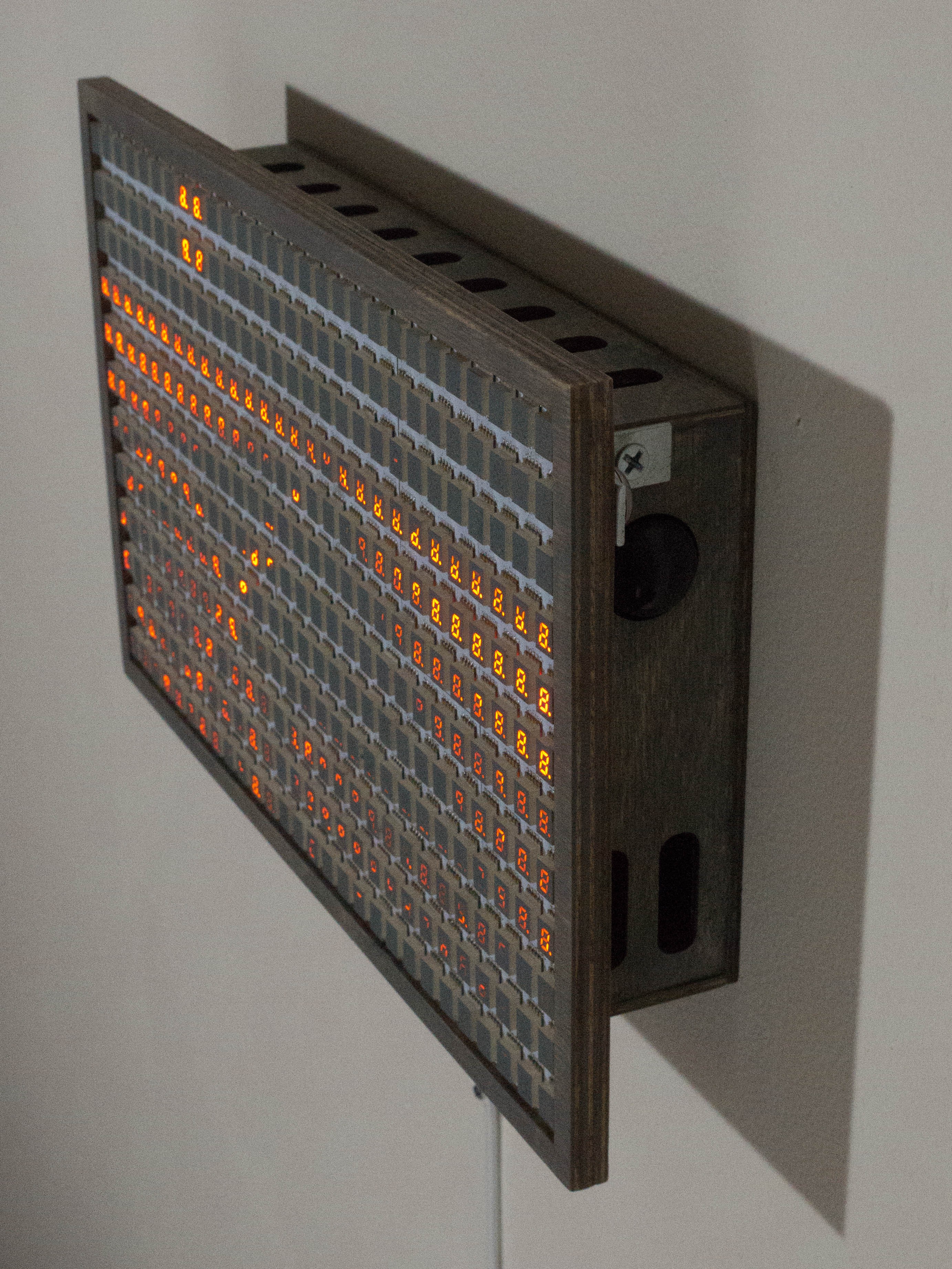
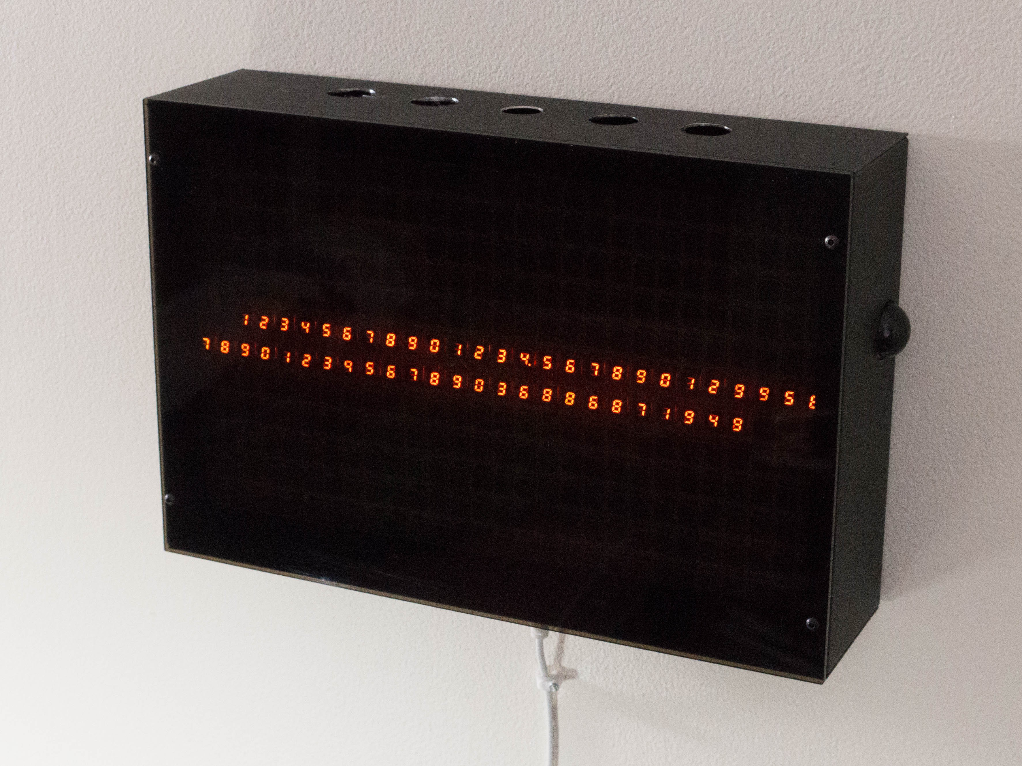
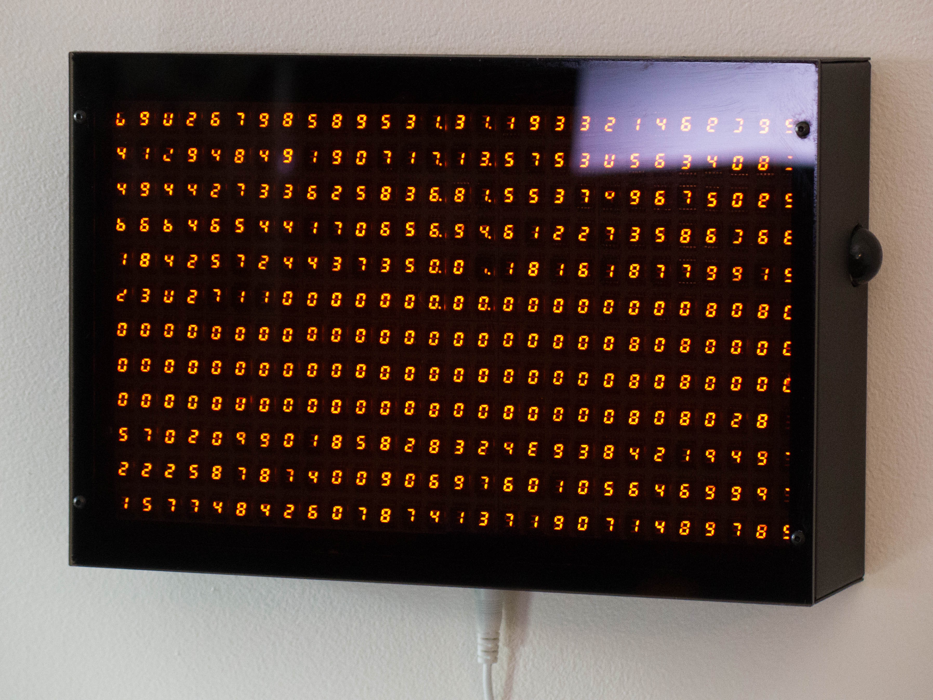
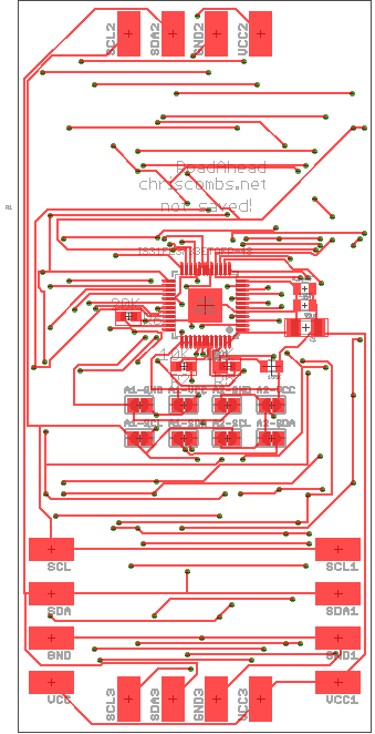
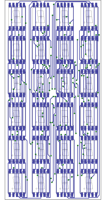
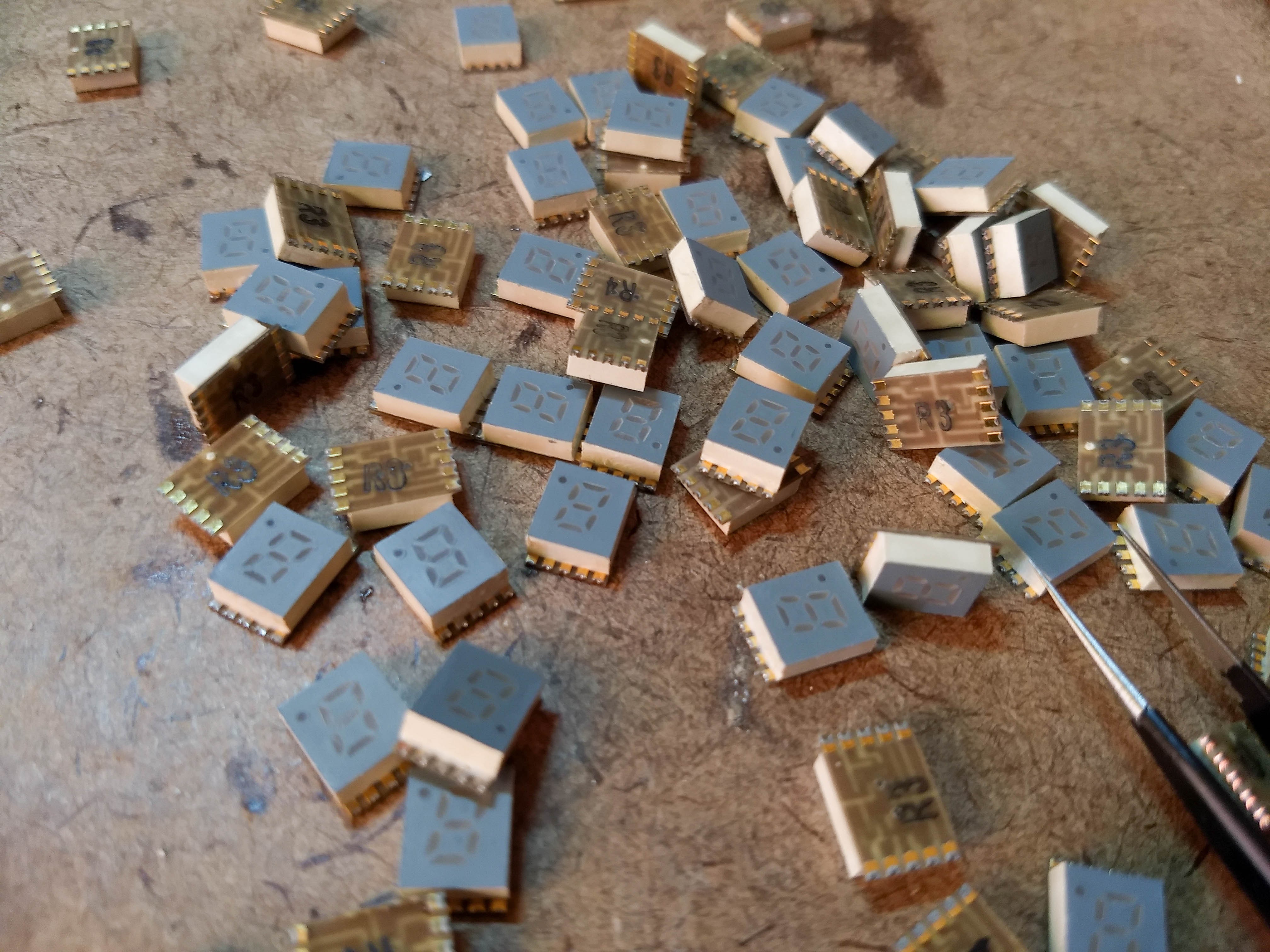
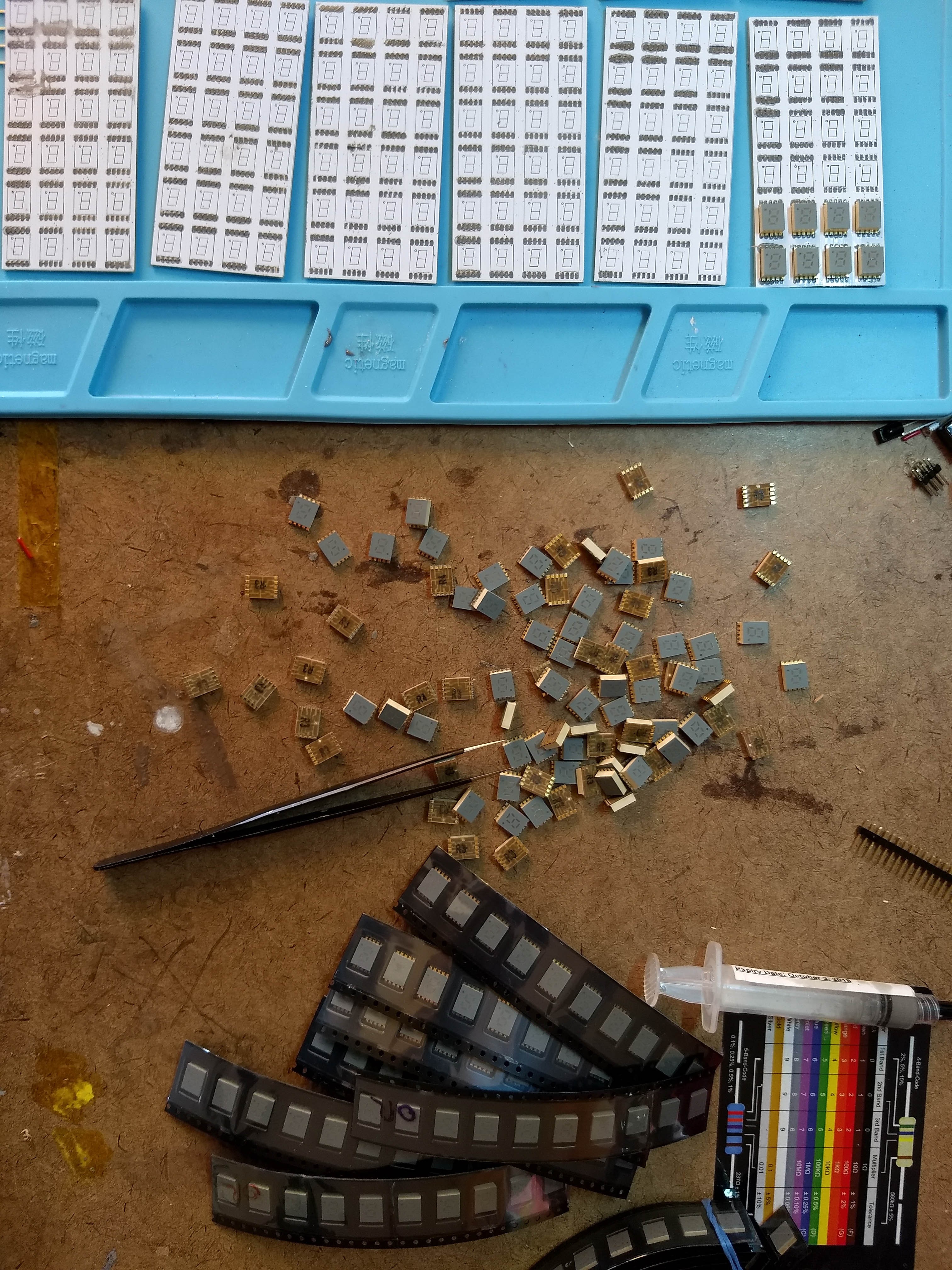
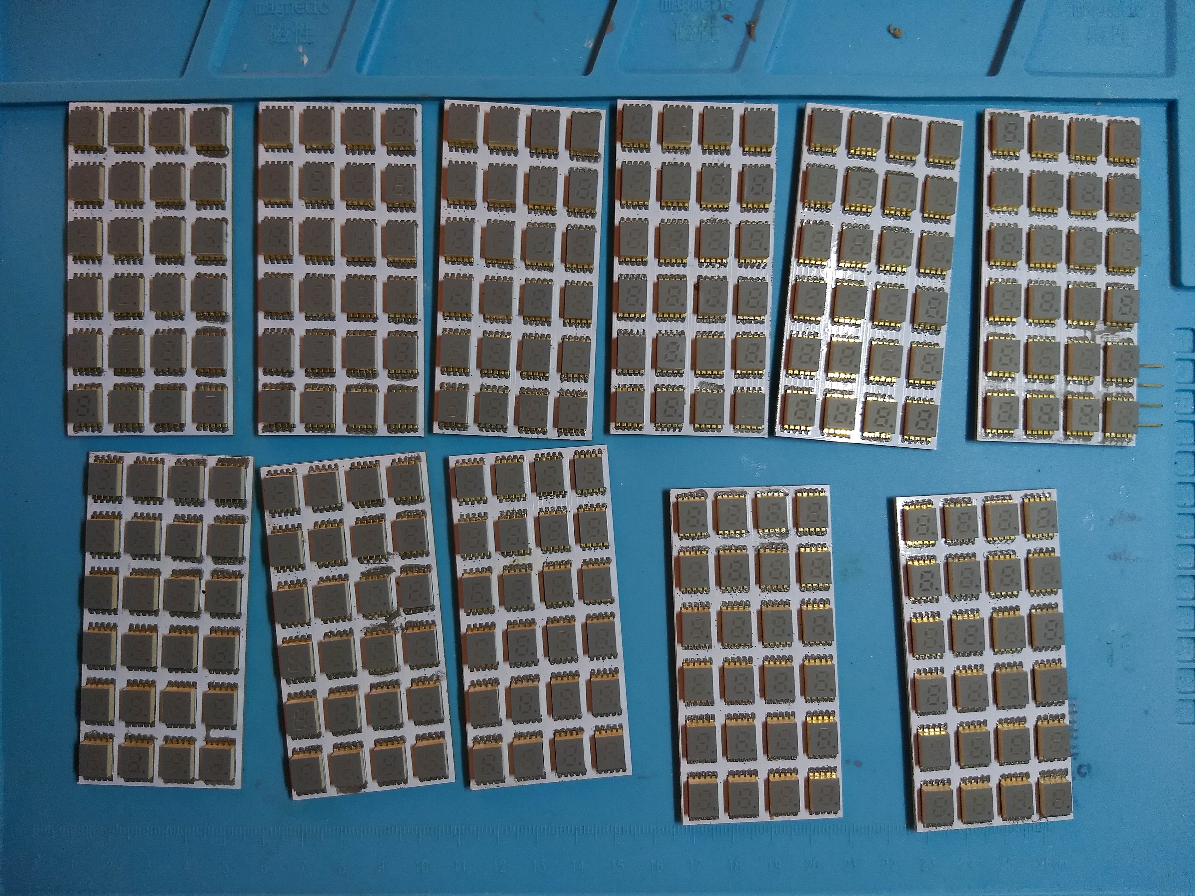
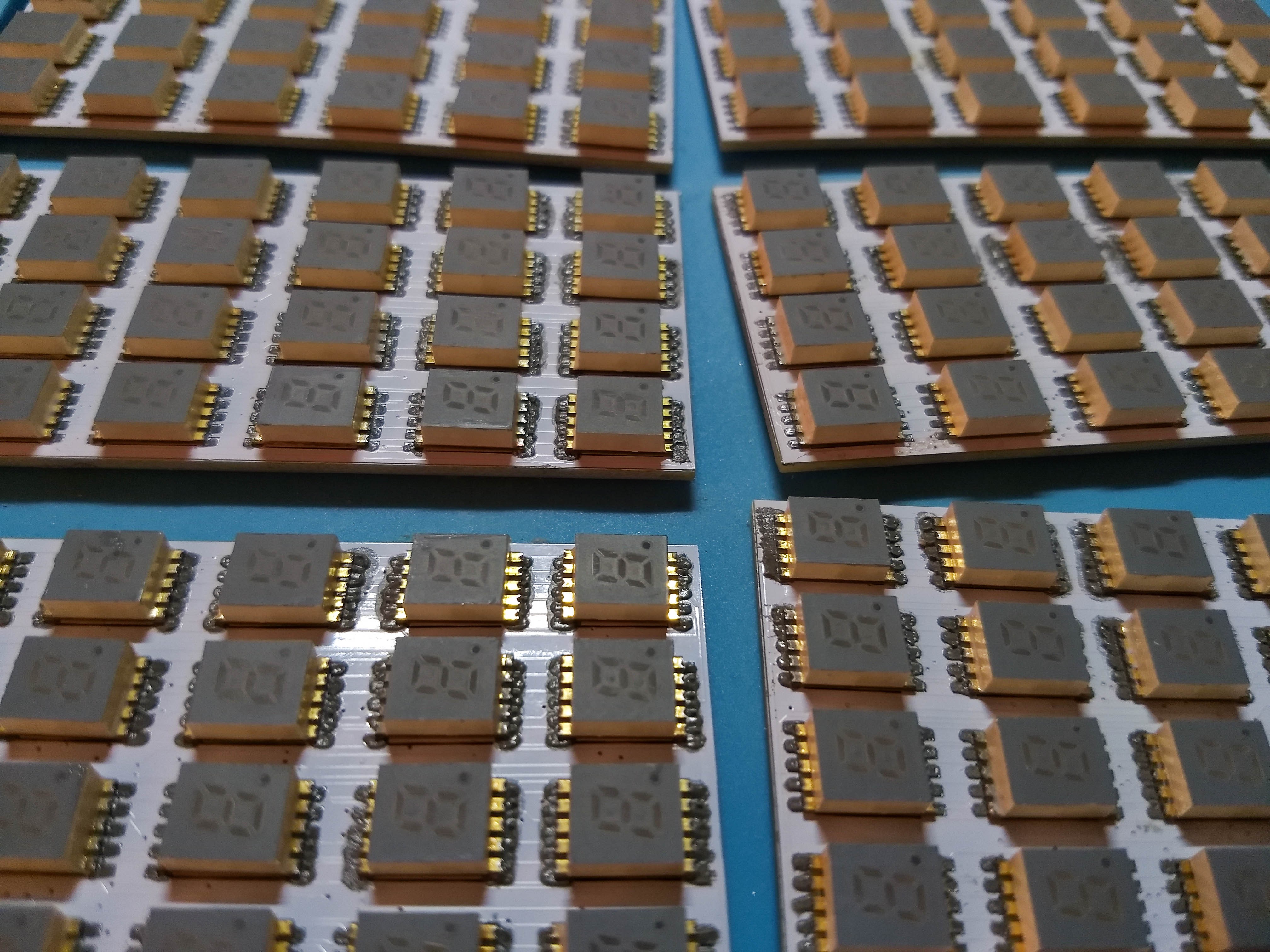
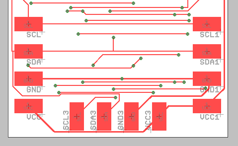
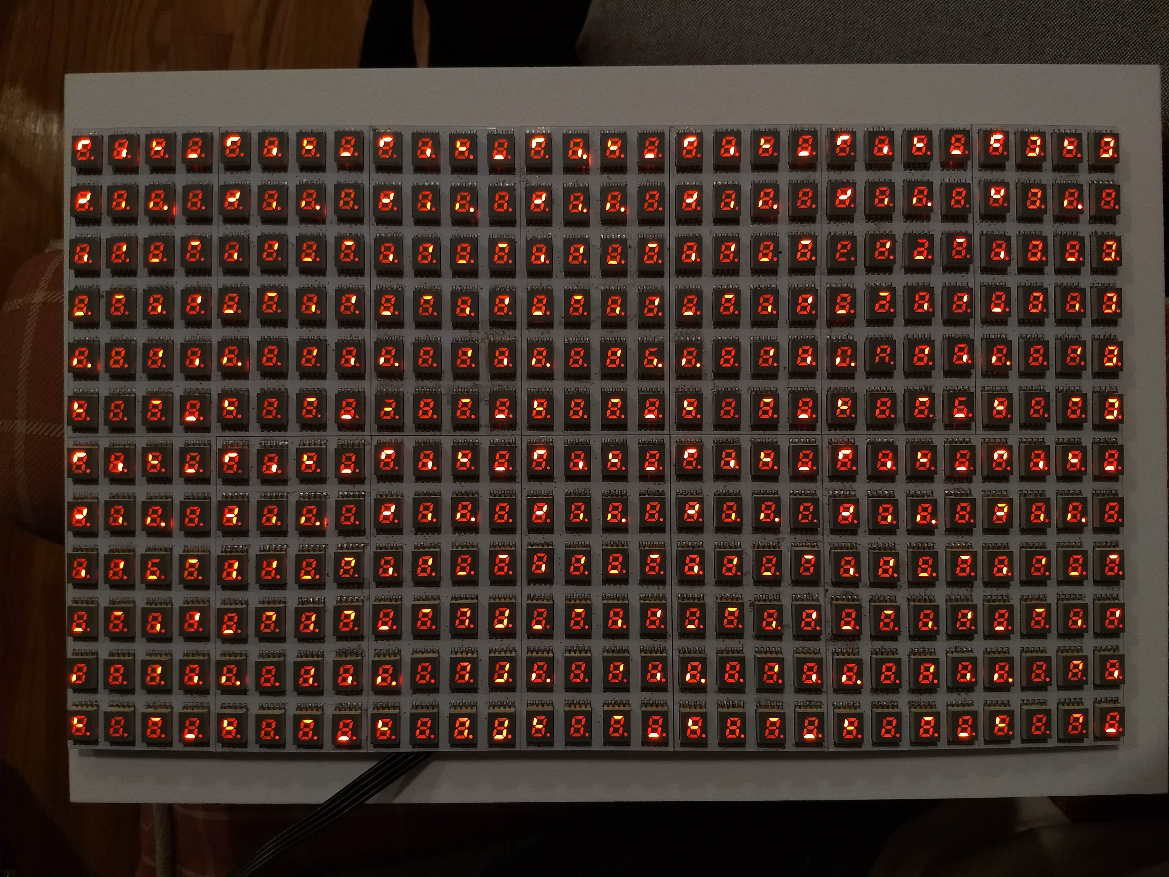
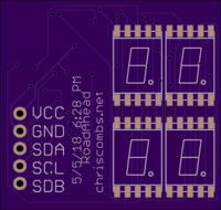
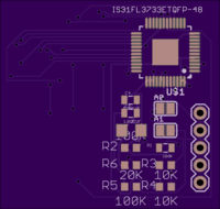
There are 336 individual vintage numeric displays attached to 14 display boards, which each have their own display controller (ISSI IS31FL3733). I designed these boards and wrote the Python driver software for their display controllers. A Raspberry Pi 3 computer runs my software, which turns a pixel grid into the very different display signals needed for the 336 numeric displays. The multiprocess software uses interprocess communication (pipes and queues) to synchronize signaling for a deep framebuffer and communicate with its peripherals.
0%
0%
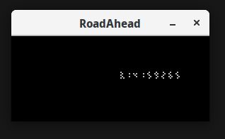
336-digit 7-segment display with per-segment PWM
Using 14 panels with ISSI IS31FL3733 I2C matrix controllers, this artwork can show 8-bit grayscale on 2,688 individual LED segments.
Become a Hackaday.io member
Already have an account? Log in.
Just one more thing
To make the experience fit your profile, pick a username and tell us what interests you.
Pick an awesome username
hackaday.io/
Your profile's URL: hackaday.io/username. Max 25 alphanumeric characters.
Pick a few interests
Projects that share your interests
People that share your interests


 deʃhipu
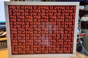
 seasleyece
 svofski
Hi, great project - do you have any video of it running?