 Jithin Sanal
Arduino Home Safety Monitor System using Ubidots
Arduino Home Safety Monitor Introduction
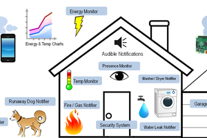
Guys, In this post, I will show you how you can create this Arduino Home Safety Monitor to identify LPG Leakage, temperature rise, ambient light, humidity and pressure of your home, especially the kitchen, and see the data in these interactive dashboards in real time.

This will also alert you via SMS, mail or Telegram, if something goes wrong or if it detects any danger. You can access this dashboard and monitor your home from anywhere in the world.
In this tutorial, I will share everything to make this one yourself. I will explain the circuit, share with you the PCB Design and layout, and the Arduino code.
Arduino Home Safety Monitor Video Tutorial
Guys. Before going further, if you find this video useful, consider supporting my channel by giving this video a like and subscribe to my channel by clicking the subscribe button below. I would really appreciate it.
What is Ubidots?
Ubidot provides a simple and secure method for sending and receiving data to and from IoT devices using the global cloud network in real time. Ubidots provides a firm platform for hobbyists, enthusiasts as well as professionals, enabling them to easily retrieve and use the sensor data around the world and turn it into something useful.
We can use the Ubidots platform to send various sensor values or other data to the cloud, store it there safely and retrieve them anytime we want using simple API calls.
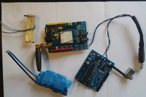
Components Needed for Arduino Home Safety Monitor
- Arduino Nano 33 IOT
- BME 280
- MQ2 Gas Sensor
- LDR
- Home Safety Monitor PCB
The Reason why I chose Arduino Nano 33 IOT is, they are very small, pin to pin compatible with arduino nano R3 and it even have an inbuilt WiFi module which will come in handy.
So lets get started.
Steps
Step 1 – Building the PCB
Guys, I have designed a PCB layout where you can easily mount your Arduino Nano 33 IOT and your Sensors, set this up without using messy wires and cables hanging around. The board is lightweight and can be powered using a 9V battery or a 9-12 V power adapter.
Here is the Circuit Diagram and the PCB Layout.

Soldering
Once you get the PCB and all the components, it’s time for you to solder them together. Solder all the components onto the board and make sure to check the polarity of the components.
I personally find soldering on this kind of PCBs a fun task, because of this pads soldering becomes very easy. The solder takes up the conical shape and get soldered from all the sides evenly. After soldering the PCB looks like this.
Step 2 – Ubidots Sign Up

Next, Go to this link and create a free account in Ubidots education. If you already have an account simply sign in with your credentials.
Step 3 – Setting Up Devices

Next we have to create a device. Since we are using Arduino for Safety moitoring, let us name the device “Home Safety Monitor”. Here you can see I have already made this device.
Step 4 – Setting Up Variables

Now click on the device you just created. Now it will show you all the variables which are linked to that device. In this project, we will need variables for storing and displaying the values for temperature, pressure, ambient light, LPG reading and Humidity.
Step 5 – Assigning Variables to Widget

Now from the dashboard, click on add new widget. There you will see several type of widgets that you can assign to your variables. These widgets gives a visual representation of the data that we will be collecting.
Step 6 – Authentication Token
In this project, we will be transmitting the data from our Arduino Home Safety Monitor to the Ubidots server using UDP Packets.
Every packets requires a TOKEN. The easiest way to get yours is clicking on “API Credentials” under your profile tab:
You’ll notice there are two types of keys in your Ubidots account:
- Tokens: Temporary...

 adria.junyent-ferre
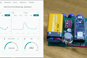
 Eric Tsai
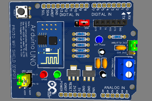
 Mrinnovative
hi, i watched the video but could not find link to the code at your blog. please share with and i would like to make my kid understand it. thank you.