 John Anderson
This project is currently shelved while I complete a couple iterations of the "1978 Heathkit Digital D&D Dice Tower" I wish I had as a kid playing AD&D. But, don't fear it will get resurrected in a number of future projects including the Digital D&D Player's Sheet, The Ultimate Hotwheels Timing Computer, and the Heathkit Delux Digital D&D Dice Tower.
Here's a quick description of the project as it exists today.
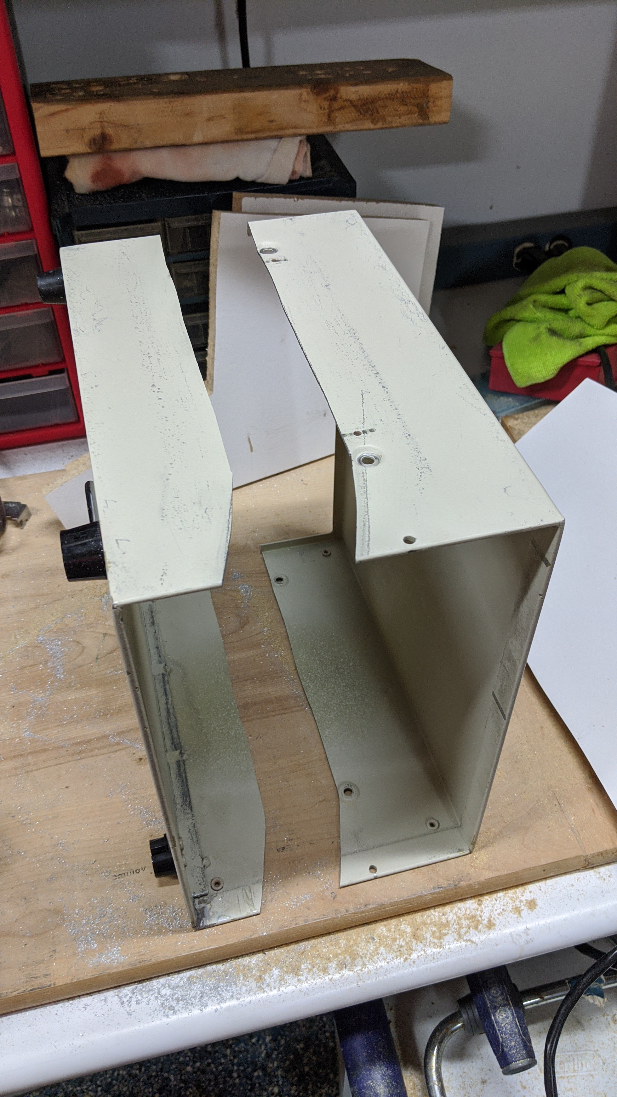
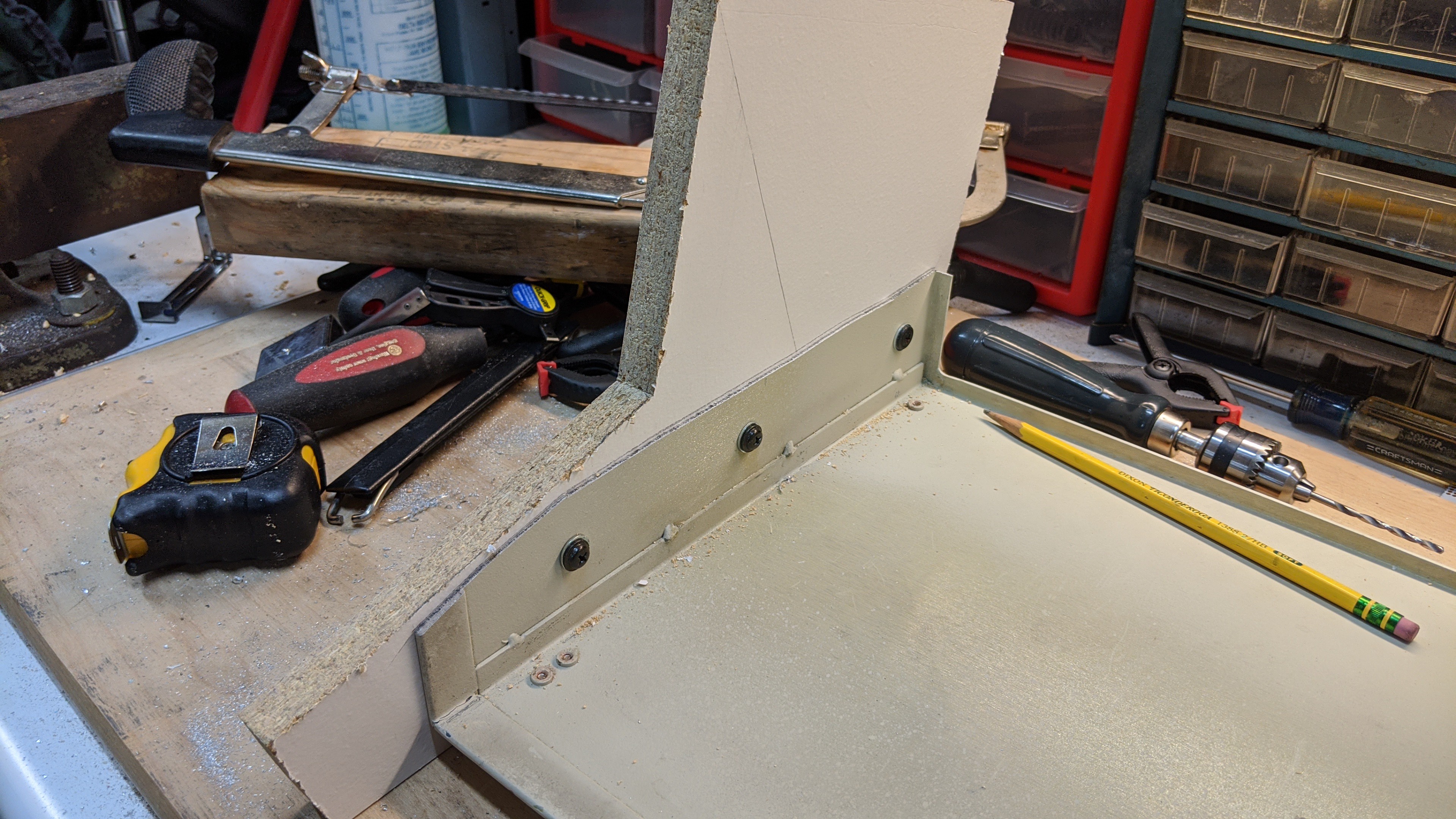
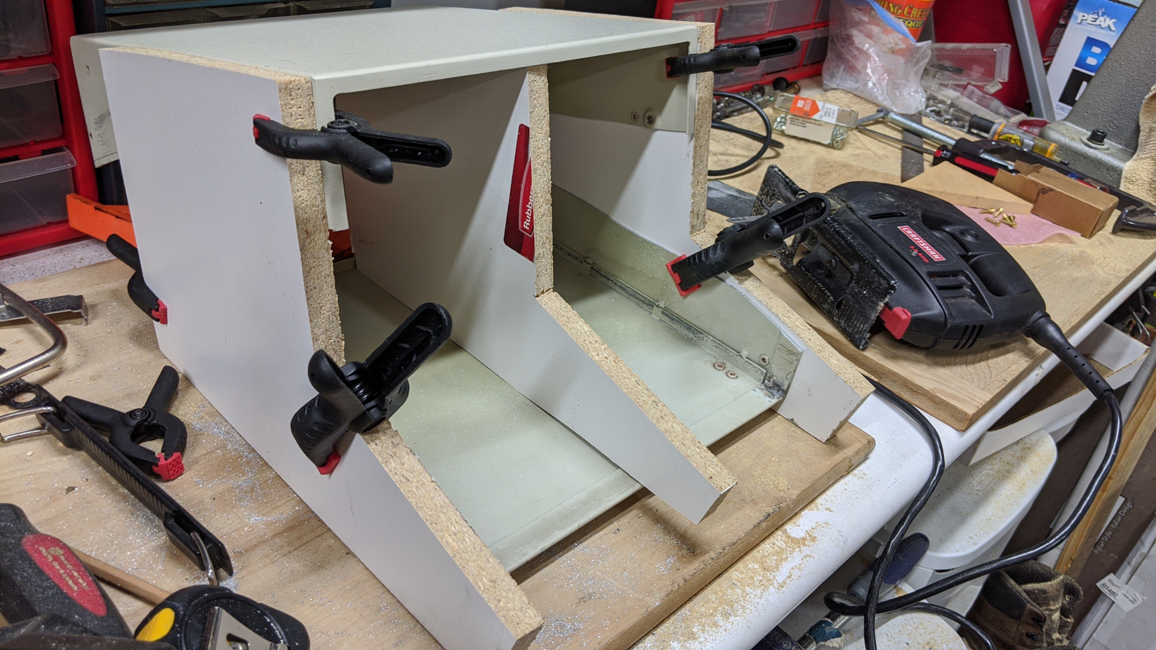
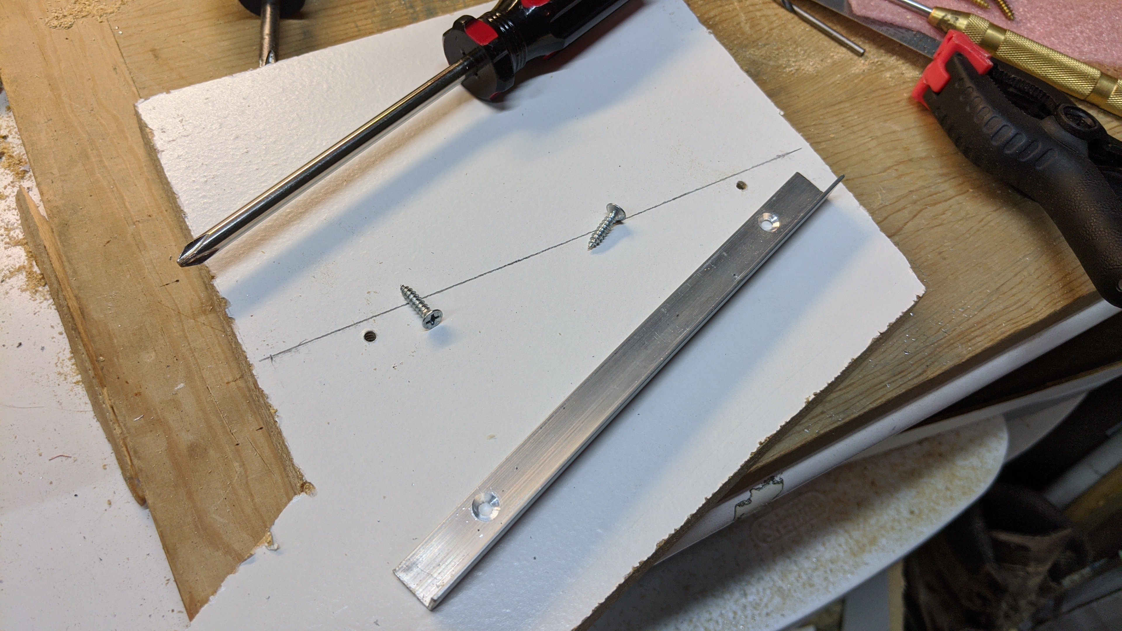
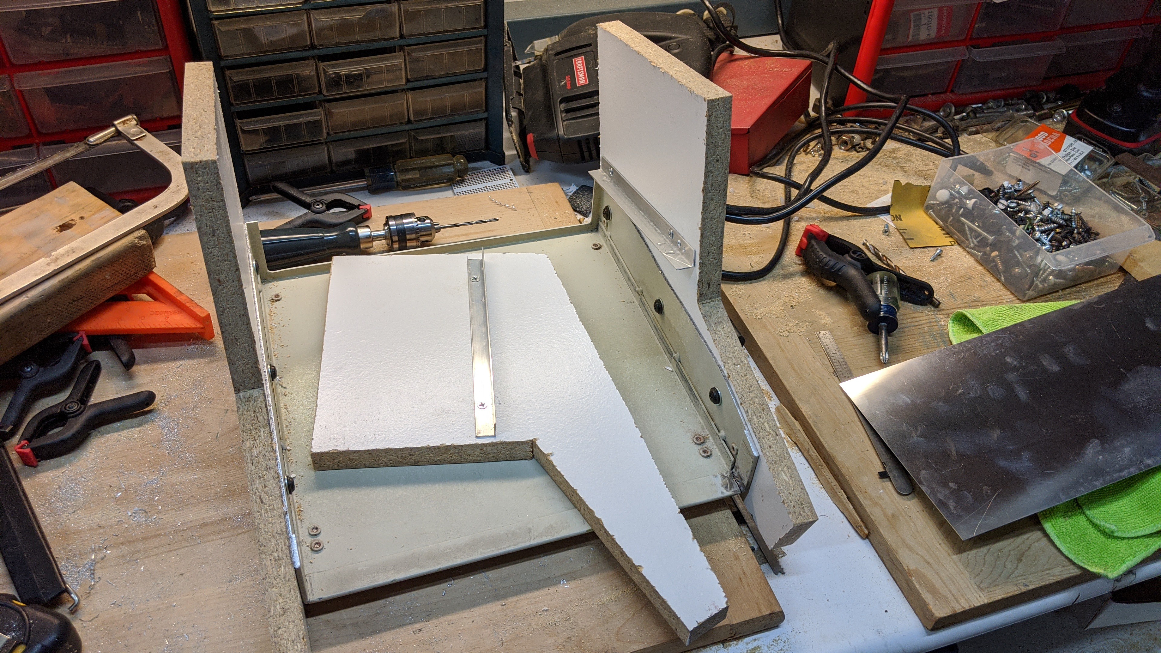
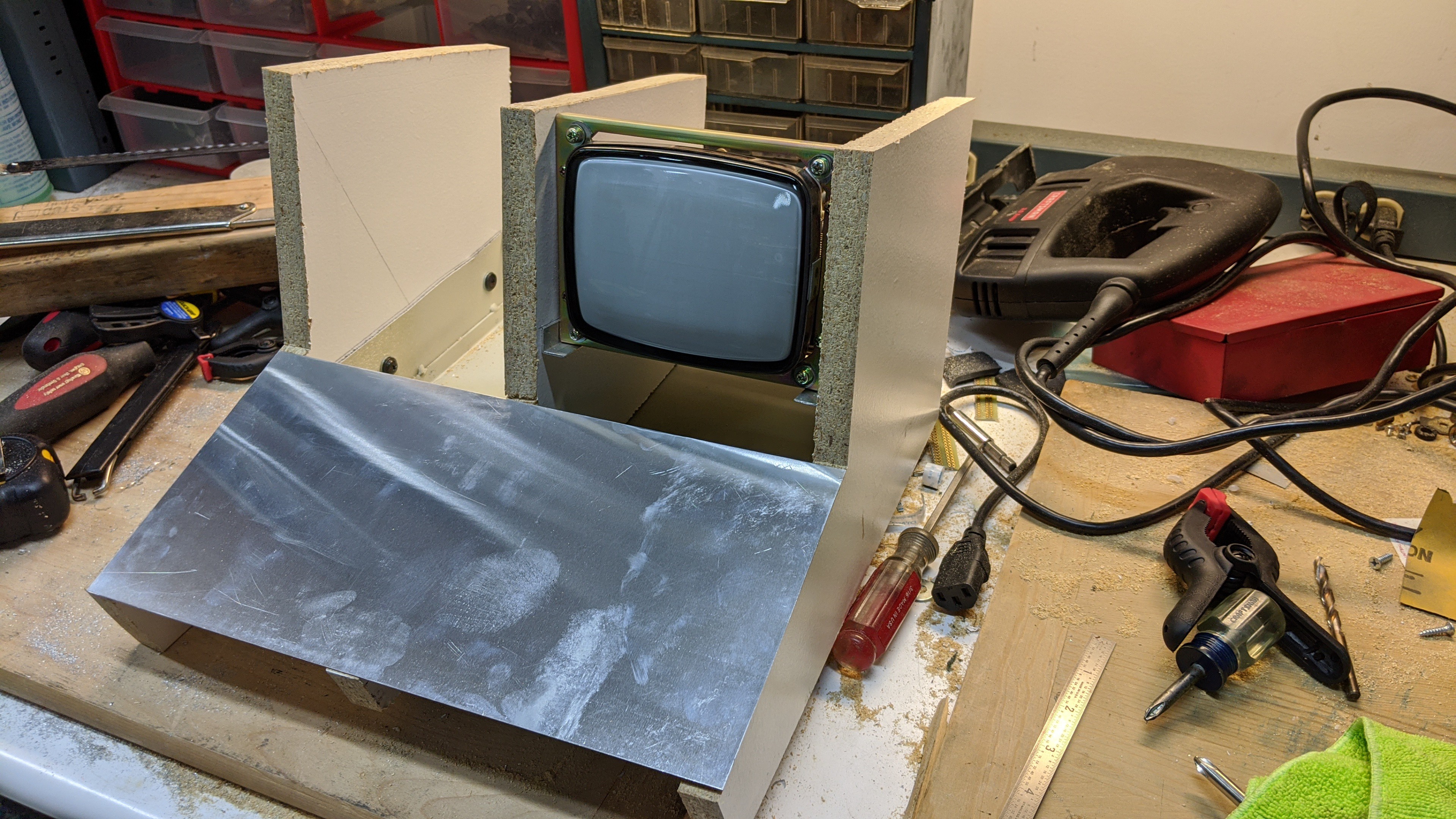
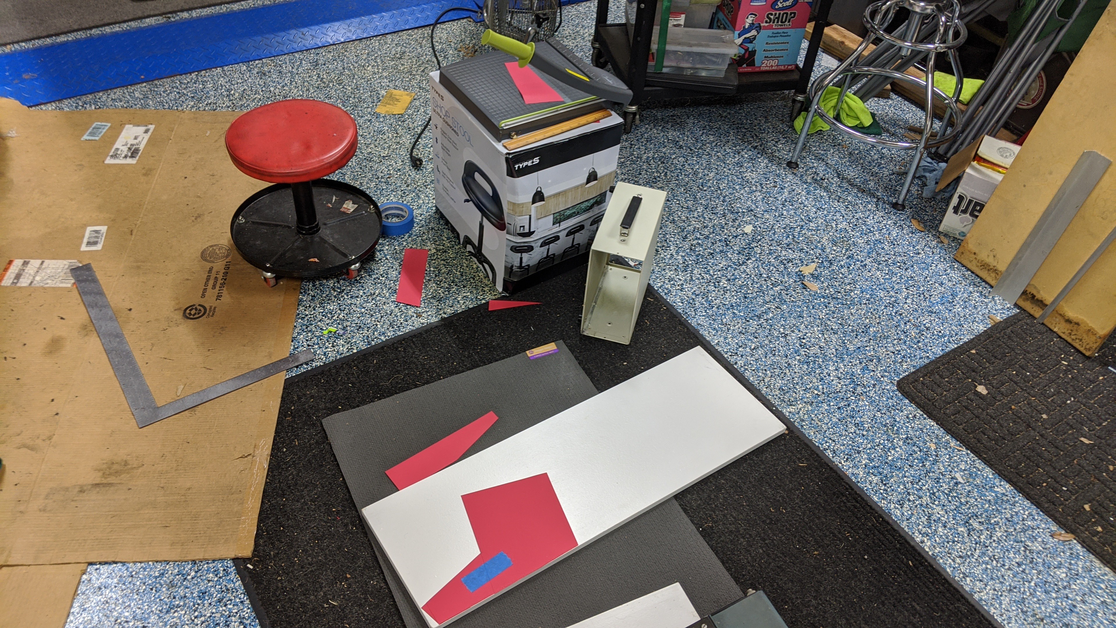
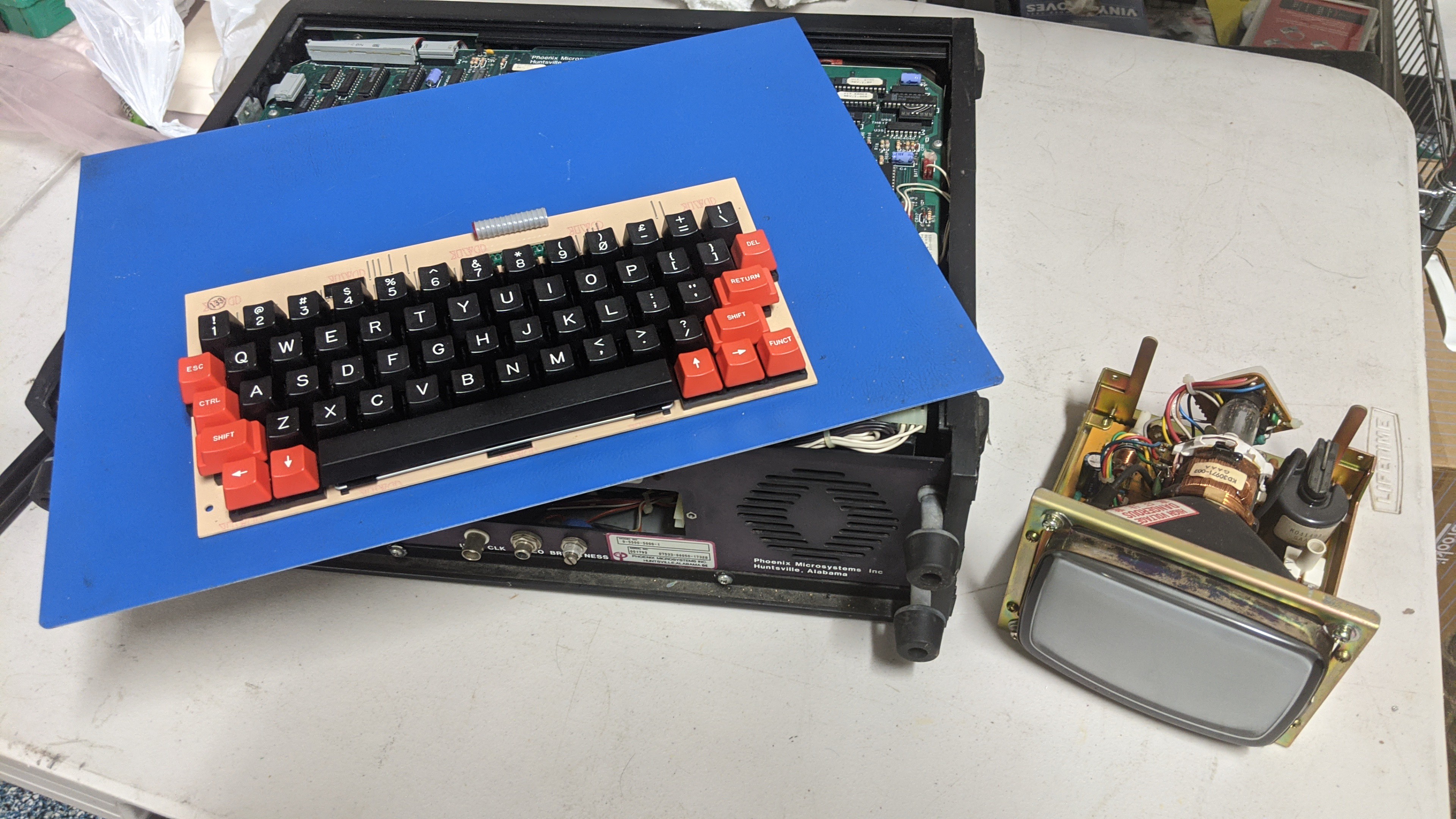
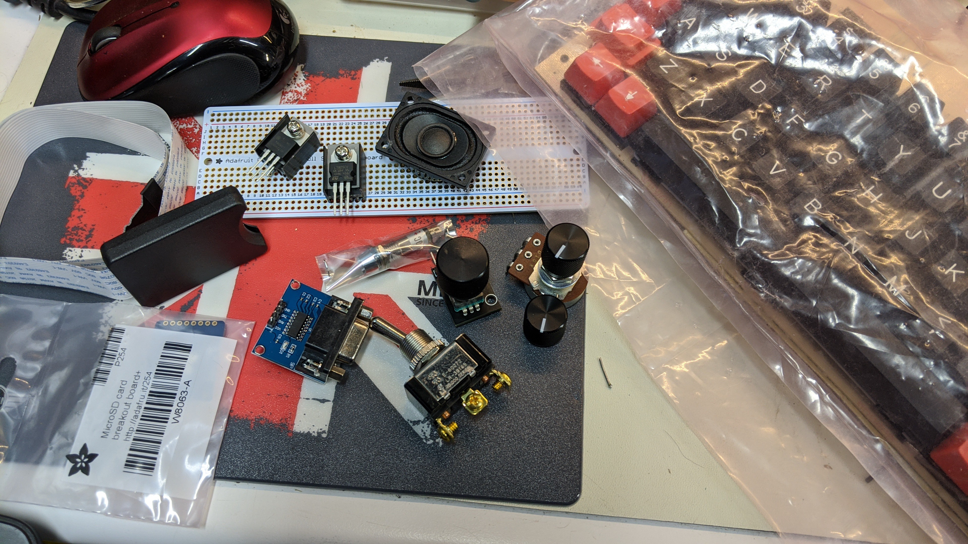
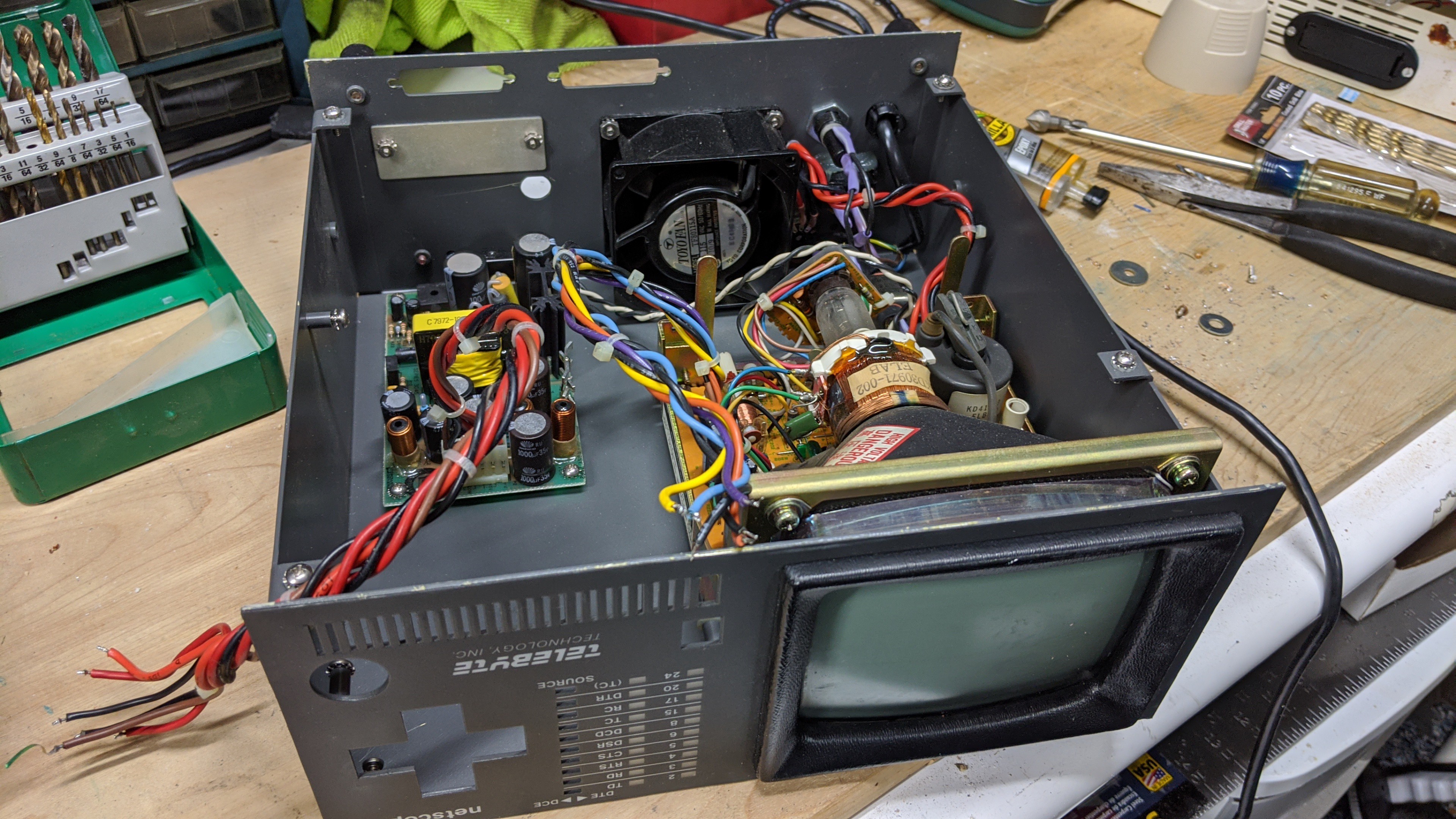
Hardware: The case was purchased from Amazon.com. It's new but certainly looks period. It was modified to contain the CRT in the top portion of the case for heat dissipation. The front faceplate was cutout for the CRT display and contains the thermal printer and a handful of buttons, a 3-way switch, and the pot for volume control. The rear faceplate has the PS/2 keyboard port, a USB type B female port, and a standard three prong AC power cord jack with integrated power switch. A cheap 12v power supply in an open frame is screwed to the inside of the rear faceplate. This 12v supply drives the CRT, controller board, and serial printer. The USB type B port is a panel mount conncetor that has a small 3 port USB hub connected inside the case. This hub has a cheap USB FTDI RS-232 interface card plugged into one port. The kind of card you can buy off Amazon for $9. It provides a TTL serial interface to the controller board that is used for serial console to the development PC for debugging. An Atmel-ICE is plugged into the other port of the USB hub. It's connected to the AVR processor on the controller board via it's ISP port. A single USB connection provides both ICE and serial console interface to the device. It's a tight fit but it's workable and comes apart for updates relatively easy. I'm impressed everything fit as well as it did.
The CRT is a 1978 Ball TV-50 5" Data Display Monitor. It was pulled from an old CNC machine (I don't know which type) and I bought it on E-bay surprisingly cheap. It's in very good condition with no burn in or any other sign of prior use.
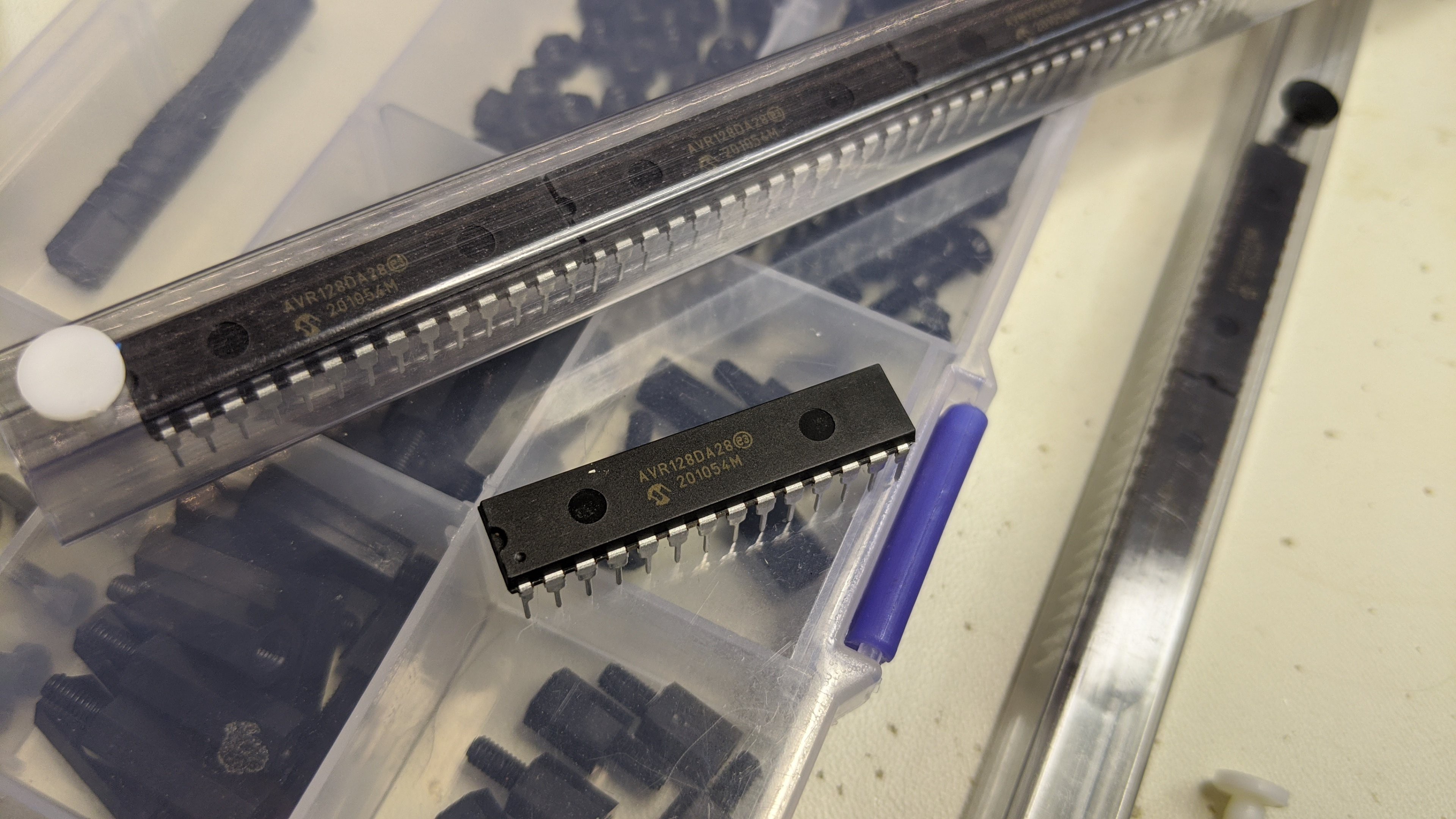
The hand built controller board was built on a Adafruit full-sized protoboard. It sports a ATMEGA1284P processor with 20 mHz crystal, 7805 voltage regulator, connector for PS/2 port on the back of the case, and a plugin daughter card. The daughter card was built on a Adafruit half-sized protoboard and contains the LM386 audio amp and the inverting transistors for the TTL CRT interface. The inverting transistors are required because the data signal to the CRT is driven by USART0 in SPI mode on the microcontroller. When the USART is idle, it drives the output high. This caused a problem with the horizontal refresh creating some ghosting and a vertical bar on the left side of the screen. To fix this, the signal from the SPI is inverted and the character bitmap was inverted as well. The horizontal sync is generated by timer/counter 1 and the vertical sync is generated on a generic output pin. There is no dedicated video controller.
Software: The software is all written in C from scratch using the Atmel Studio 7.0 IDE and associated GNU toolchain. It's architect-ed to create a dedicated application devices. So, it doesn't provide a loader like a user OS. However, it's organized into drivers (CRT, serial, sound, ps/2 keyboard, etc.), services (text windowing manager, UI objects such as text box/radio button/check box/menu, file system, etc.), a simple task/screen manager, and application tasks that are organized into "screens". The user application is written as a series of files that represent each screen of the application. Each file has at least a minimal set of global data structures and a couple function handlers that implement the screen. The data structures describe the UI objects that comprise the screen and the function handlers provide the functionality for these objects. The task/screen manager parses the data structure to dynamically load each screen's data into RAM when that screen has the focus. If a subsequent screen is navigated...
Read more »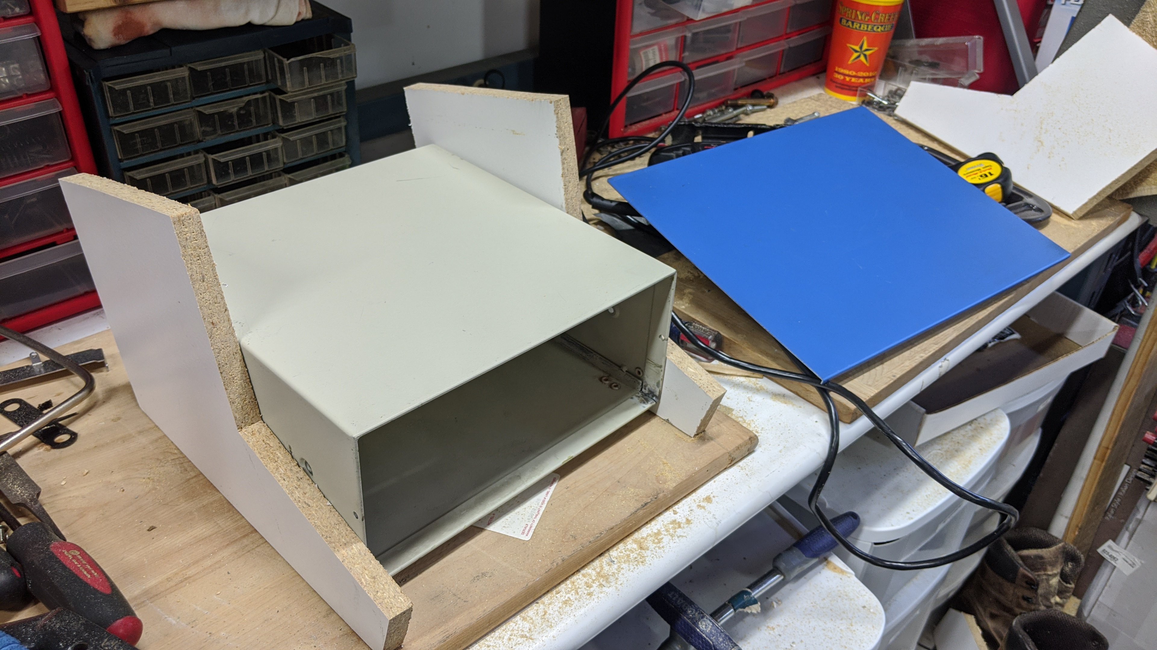


 Nick Scratch
 Mjnurney
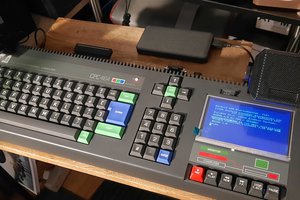
 Michael Wessel
 eric
eric
The crt is really nice looking and fits the time period well. Not as easy as an lcd, but that was not the point here.