MS-BOSS
Description of the pulser
This is a simple flat-top avalanche pulser with integrated power supply for the avalanche transistor circuit and trigger circuitry. It was intentionally made to have the top of the pulse as flat as possible, which resulted in very nasty falling edge.
Purpose of the circuit and its main characteristics
This pulser was made in hope to use it to measure reflections on cables. However, using the transistor 2SC5773, it was not possible to obtain faster risetime than about 700 ps. This allows to measure reflections, but the resolution is quite limited due to the shape of the pulse (slow risetime and a backlash after the falling edge). Maybe using some other transistor and changing the compensation circuitry, it could be made better. The length of the pulse can be set by cutting according storage coaxial cable.
Features
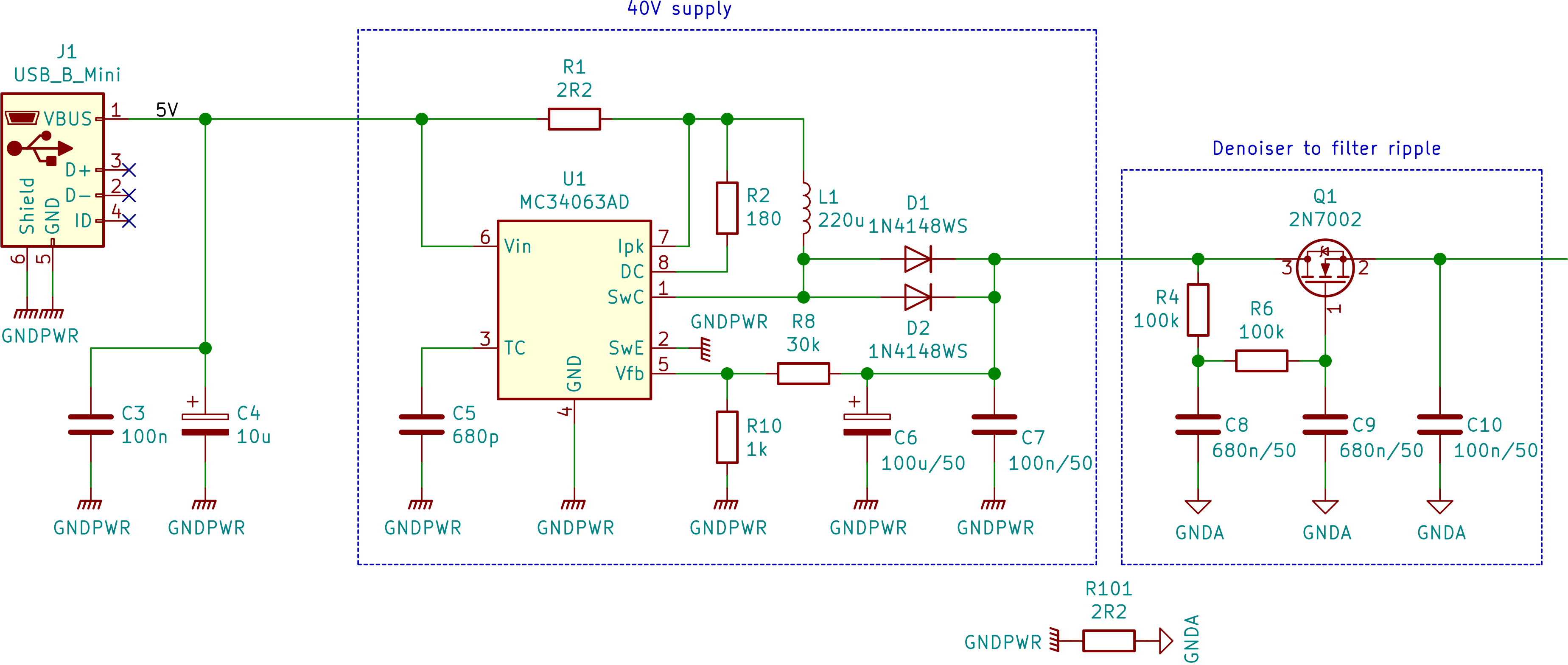
Power supplies
The pulser contains a 40V power supply followed by denoising network and 6V - 35V regulated linear supply to set the avalanche voltage. The whole board is powered from 5V using Mini USB-B, consuming less than 100 mA.
NOTE: It was later found out that the regulator is somehow nonlinear and behaves as a bistable circuit when going over 40V, thus it was later modified with lower upper voltage limit.
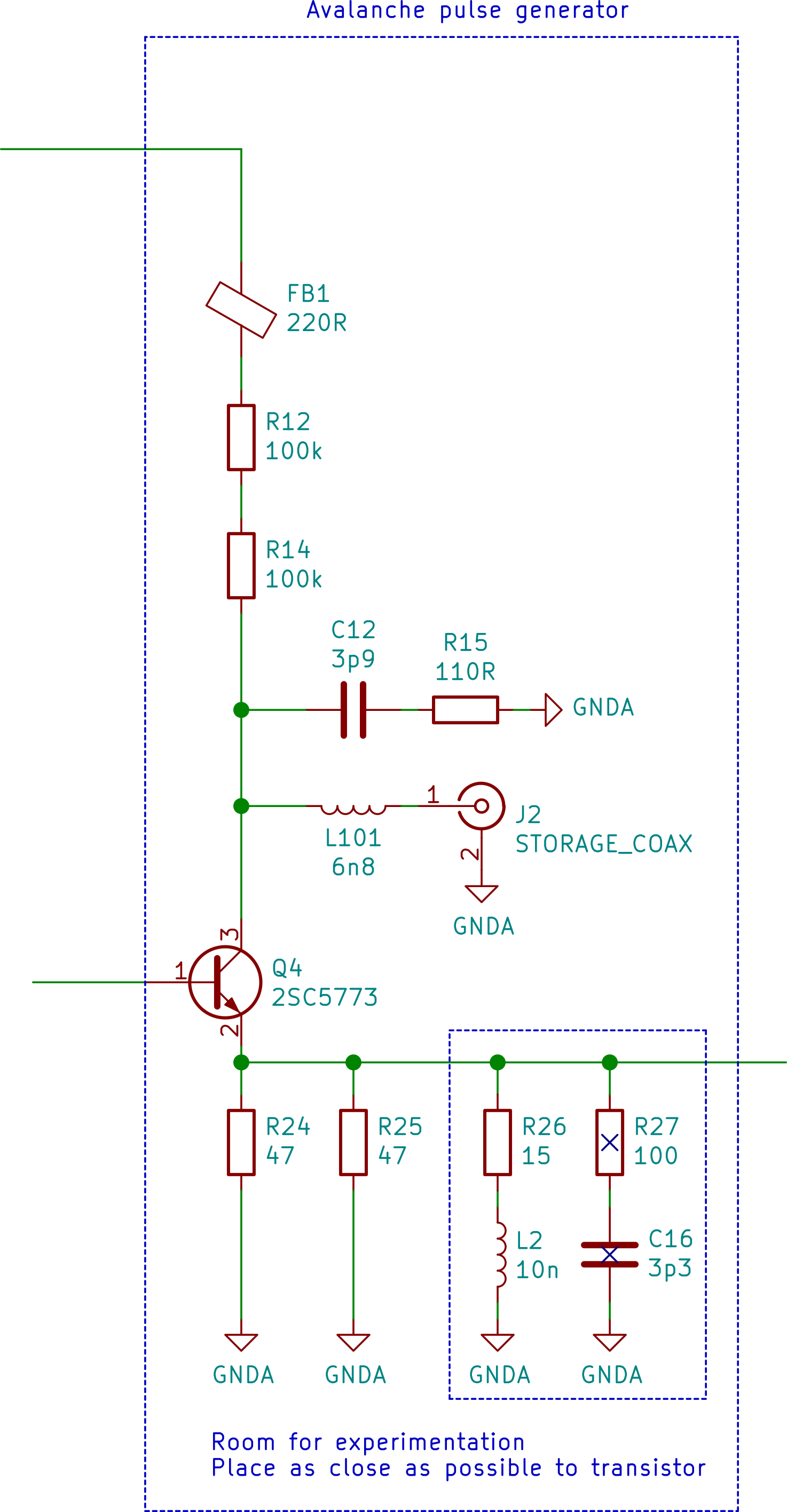
Avalanche pulser
The avalanche pulser uses 2SC5773 transistor (6V NPN, fT=10.8 GHz @ 50 mA). The compensation circuitry makes the output pulse a nice clean rectangular pulse with a flat top with no visible ringing (invisible with 1 GHz oscilloscope, to be precise), however there is a not very nice backlash after the falling edge (see pictures). The transistor does not self-avalanche when set properly, it has to be triggered by external source. I used 8-10 kHz triggering during the development and use. There are 2 other SMA connectors, one for coaxial cable where energy for the pulse is stored (length of the cable determines length of the pulse) and one where the pulses are output.
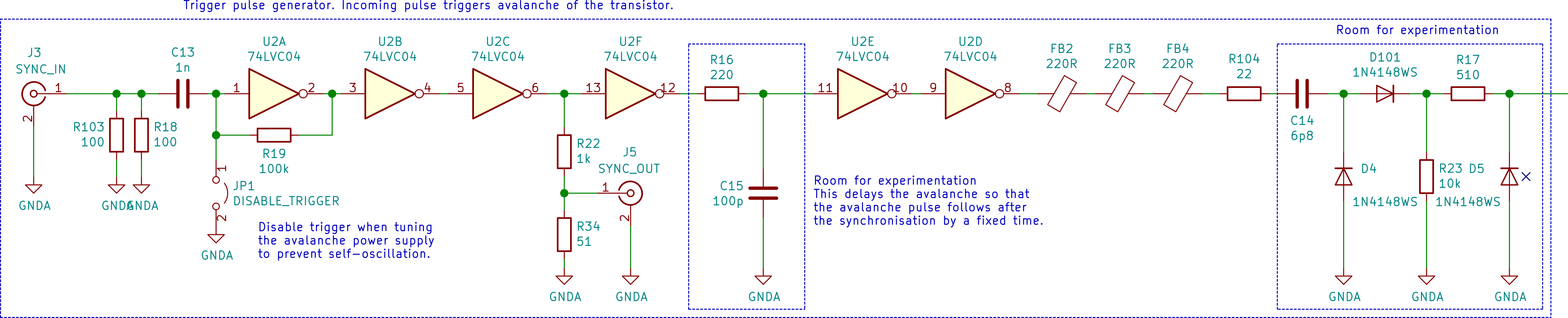
Trigger circuitry
The trigger circuitry triggers avalanche on rising edge of the input trigger signal. There is RC circuit which sets the time between the trigger and avalanche to allow for pre-trigger on oscilloscope. However, it seems to have quite large jitter. There is a trigger output which you can connect to oscilloscope (the avalanche happens on falling edge of the TRIG OUT). The trigger circuitry can be inhibited using the jumper JP1 when tuning the avalanche voltage.
Attenuators
There are 2 attenuating sections giving 11.3 and 7.9 dB attenuation. The first one is mandatory as it is an impedance matching circuit. The second one is just a standard attenuator and can be omitted.

How to use it as a simple standalone time-domain reflectometer
Connect square wave generator to the SYNC_IN port. Connect an oscilloscope to the SYNC_OUT port and to the PULSE_OUT port.
Connect the coaxial cable to be measured to the STORAGE_COAX port. The cable MUST NOT have any shorts in it or any low impedance termination, because it is connected to the collector network and it would load the 200k resistor and the transistor would not avalanche. This severely limits the usability, so this mode is not recommended.
How to use it as a pulser for general use
Connect square wave generator to the SYNC_IN port. Connect storage coaxial cable to the STORAGE_COAX port. You should use some 50 Ohm cable with low losses, ideally some rigid or semirigid cable. I used RG-174 because I had a lot of it on hand and the circuit is tweaked for use with the RG-174 (I used about one meter of the cable which gave me about 8 ns long pulse). Connect the PULSE_OUT port to anything you want (50 Ohm terminated).
Measurements
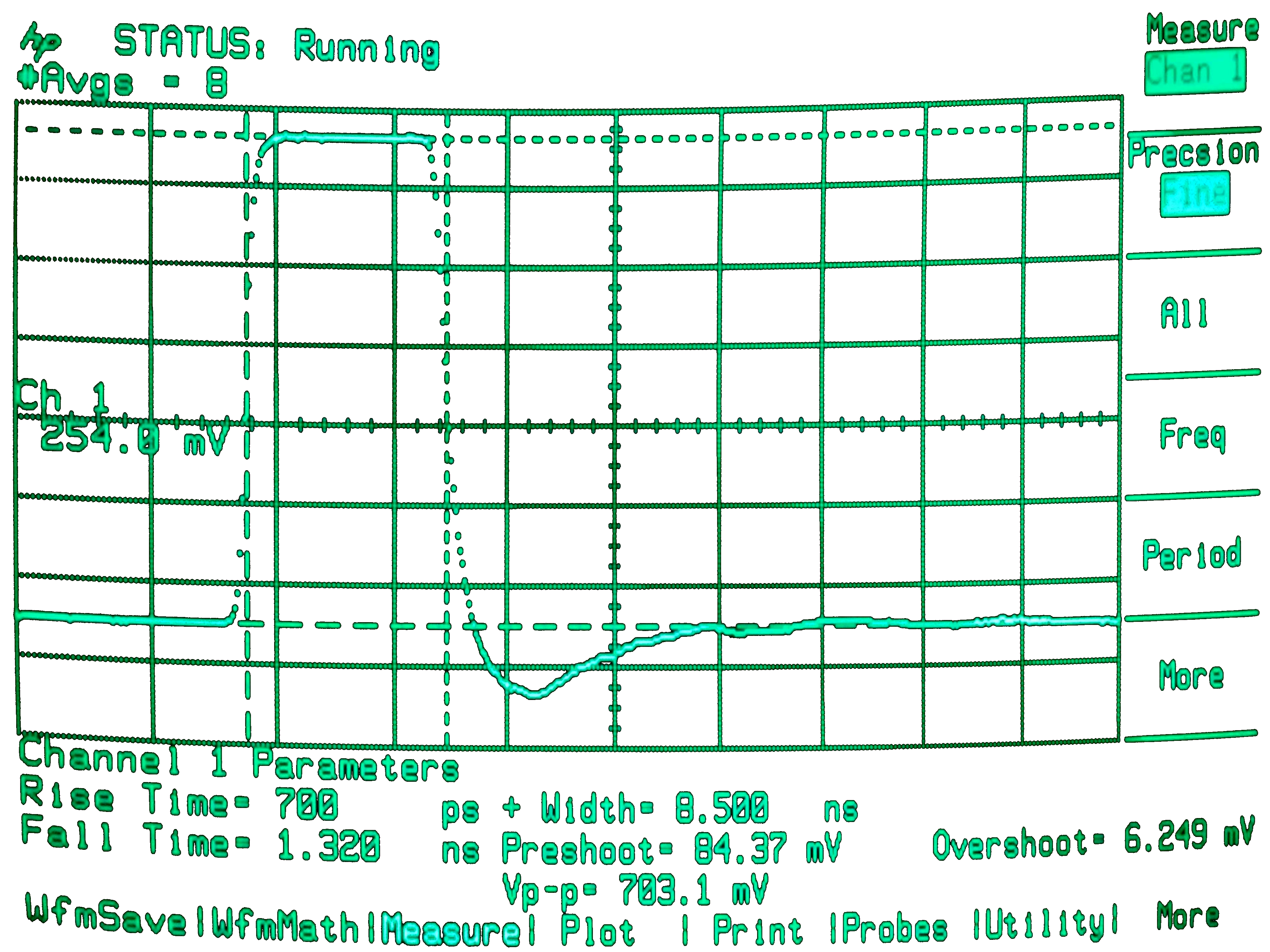
Whole pulse
The pulse is very flat on its top, the rise time is about 700 ps, fall time about 1.3 ns. Length was set to about 8.5 ns.
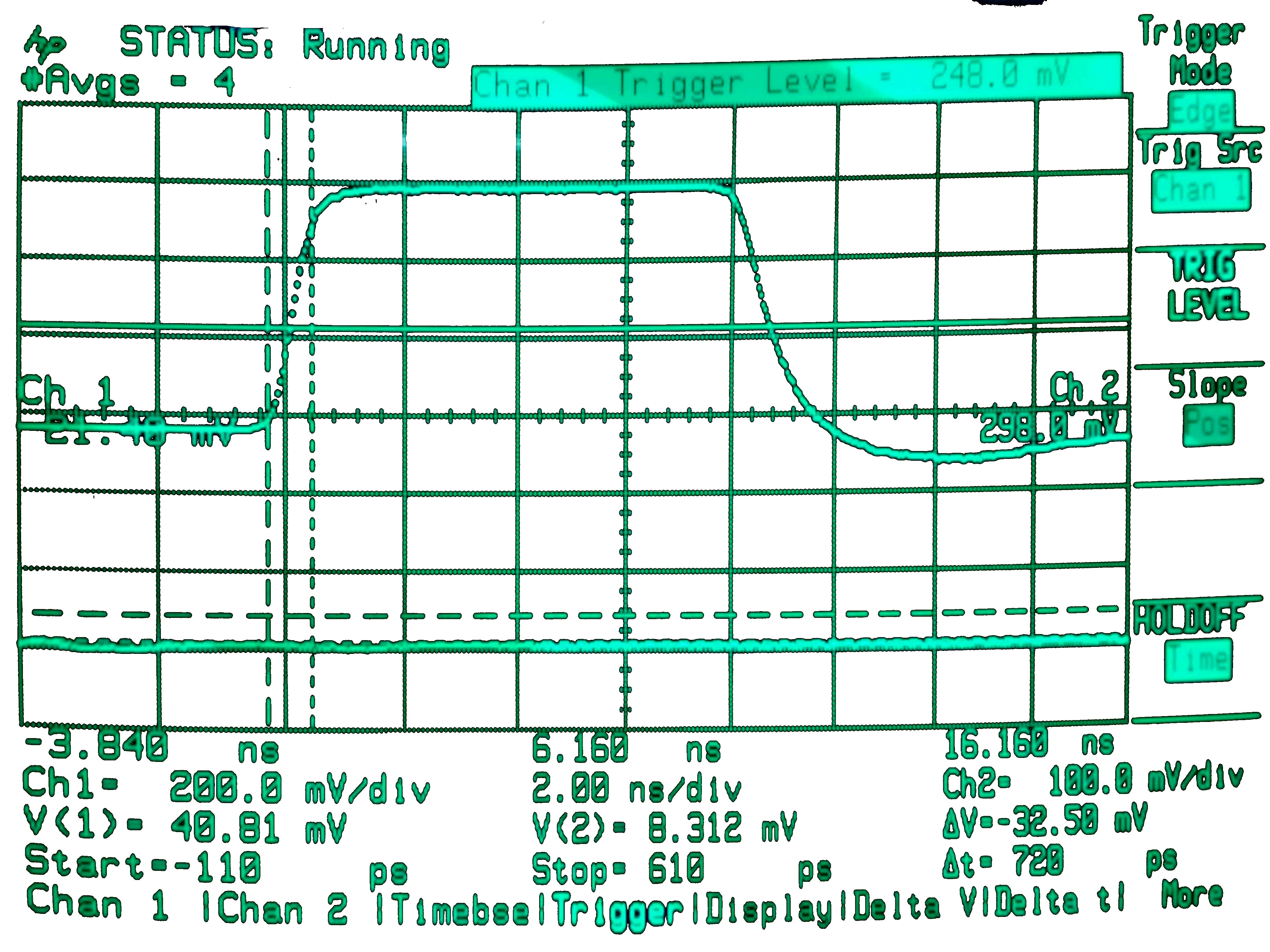
Zoomed-in pulse
Zoomed-in rising edge
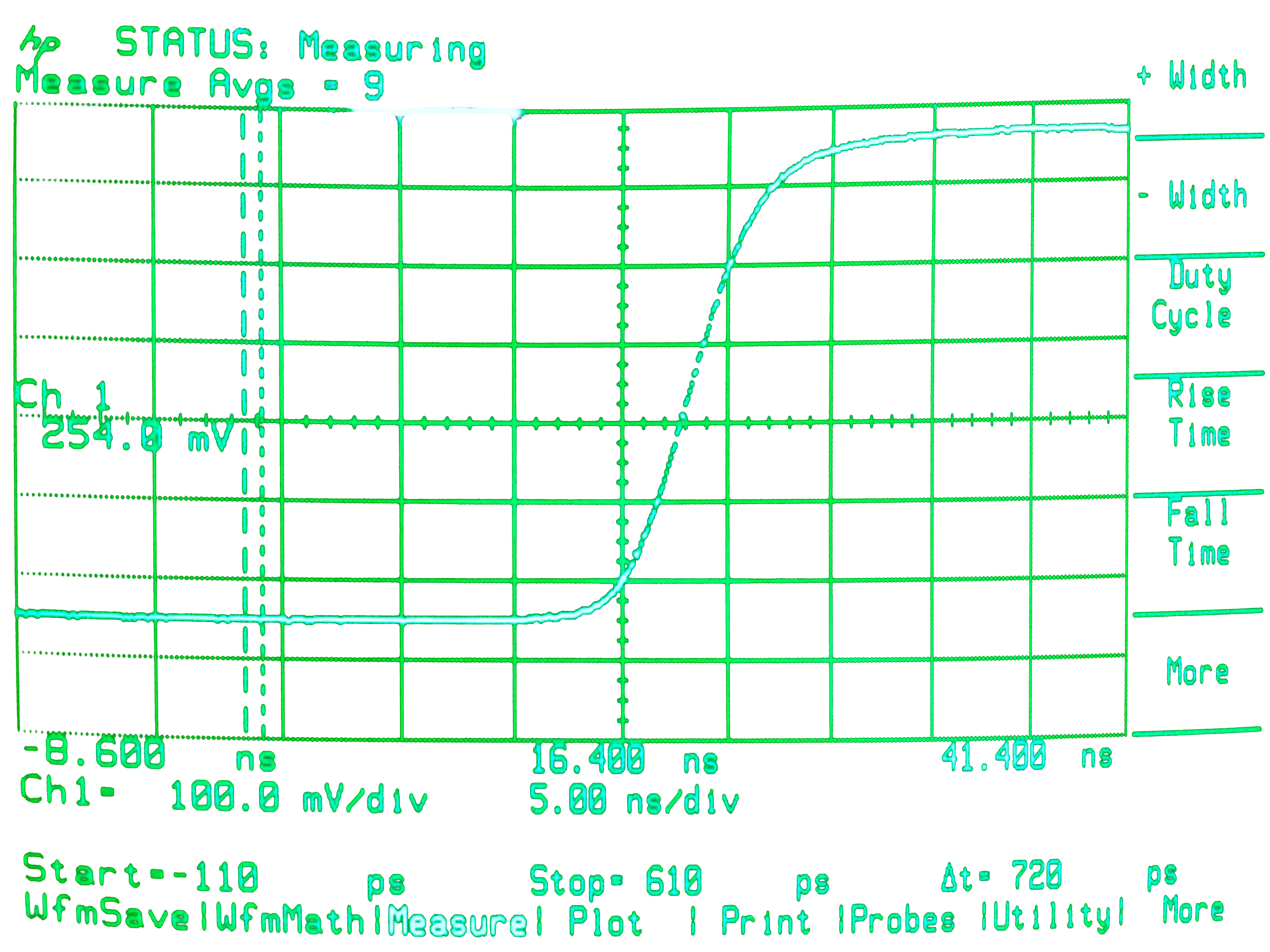
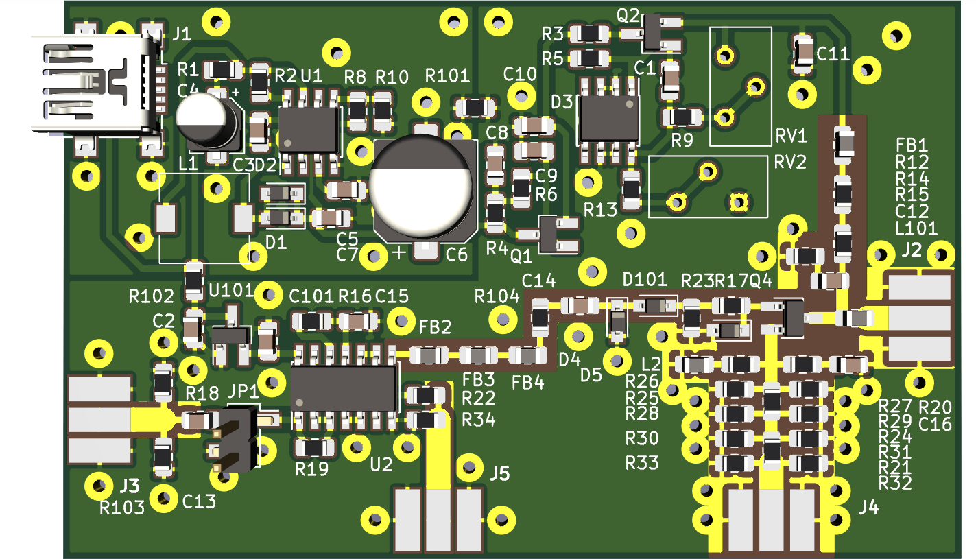
Image of the board in 3D
References
AN-94: Slew Rate Verification for Wideband Amplifiers
Read more »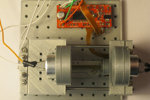
 Andrew Ferguson
 mihai.cuciuc
 Hulk
Hulk