MS-BOSS
Purpose of the circuit and its main characteristics
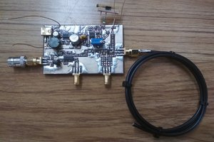
This board should be used with the avalanche pulse generator to measure cable reflections. The PCB includes trigger generator for the pulse generator, passthrough USB for power supply and resistive splitter to allow connecting a cable and 50 Ohm terminated oscilloscope. The splitter offers 3 ports, 50 Ohm terminated. The signal passes directly over the CABLE port. Insertion loss of the splitter from IN to OUT port is about 20 dB.
Trigger generator
The trigger generator can output 2, 4 or 8 kHz square wave. 8 kHz is recommended for the avalanche pulse generator.
Schematic diagram

How to use it with my avalanche pulse generator
Connect the avalanche pulse generator to the IN port and TRIG_OUT port. Connect Mini USB B cable as power supply. Connect USB cable to the USB A port and connect the cable to avalanche pulse generator. Connect DUT to CABLE port. Connect 50 Ohm terminated oscilloscope to the OUT port. Connect second oscilloscope input or trigger to SYNC_OUT port of the avalanche pulse generator. The avalanche pulse generator has to be modified to be usable with this board due to the high insertion loss - you have to remove both the attenuators so that in the emitter there are only the 2x 47R resistors and compensation network and there should be 27 Ohm resistor between output and the emitter network so that it is roughly 50 Ohm terminated (in fact, the termination heavily changes during the avalanche pulse, but this does not matter as long as reflections return after the pulse ends).
How to use it with some other pulse generator
Connect pulser output to IN port, connect cable under test to the CABLE port. Connect oscilloscope to the OUT port. Separate trigger has to be provided by your pulser board.
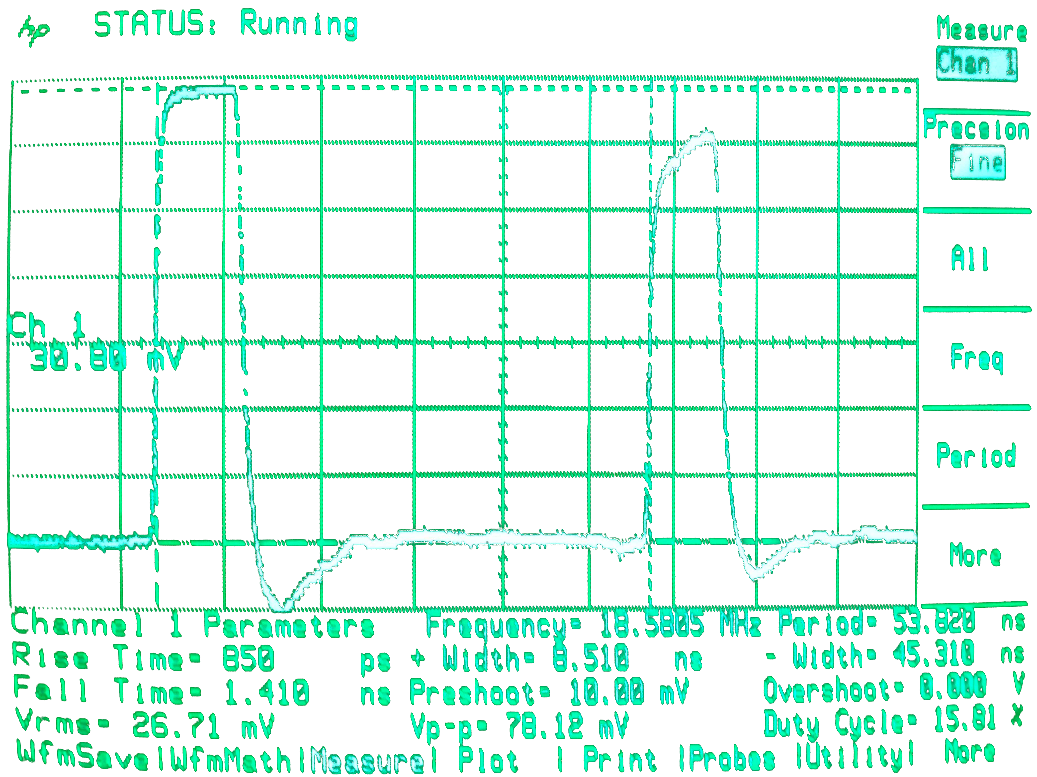
Oscillogram of an unterminated (open) 50 Ohm cable
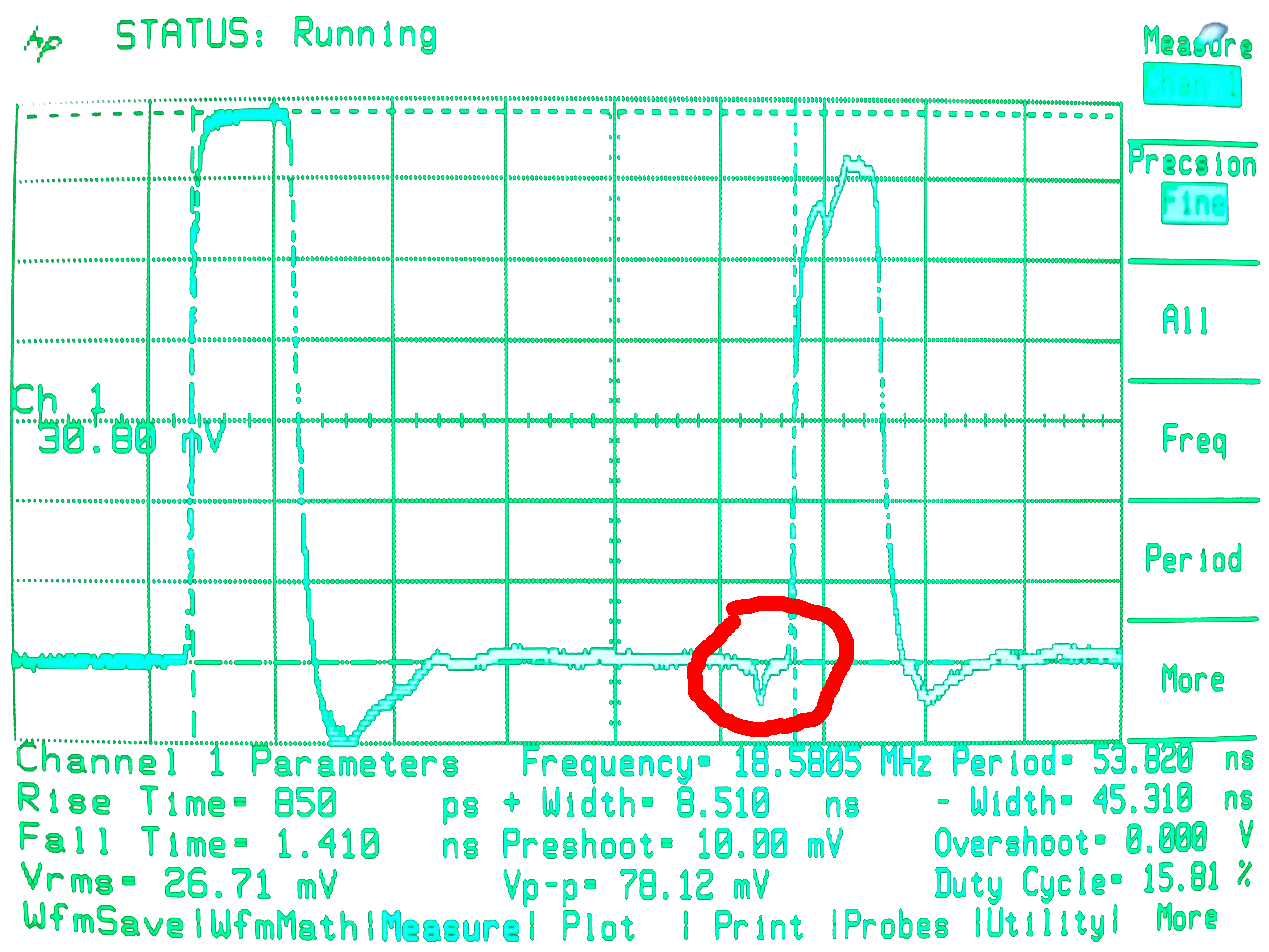
Oscillogram of an unterminated (open) 50 Ohm cable with defect some 35 cm form the end caused by being heavily pressed using pliers
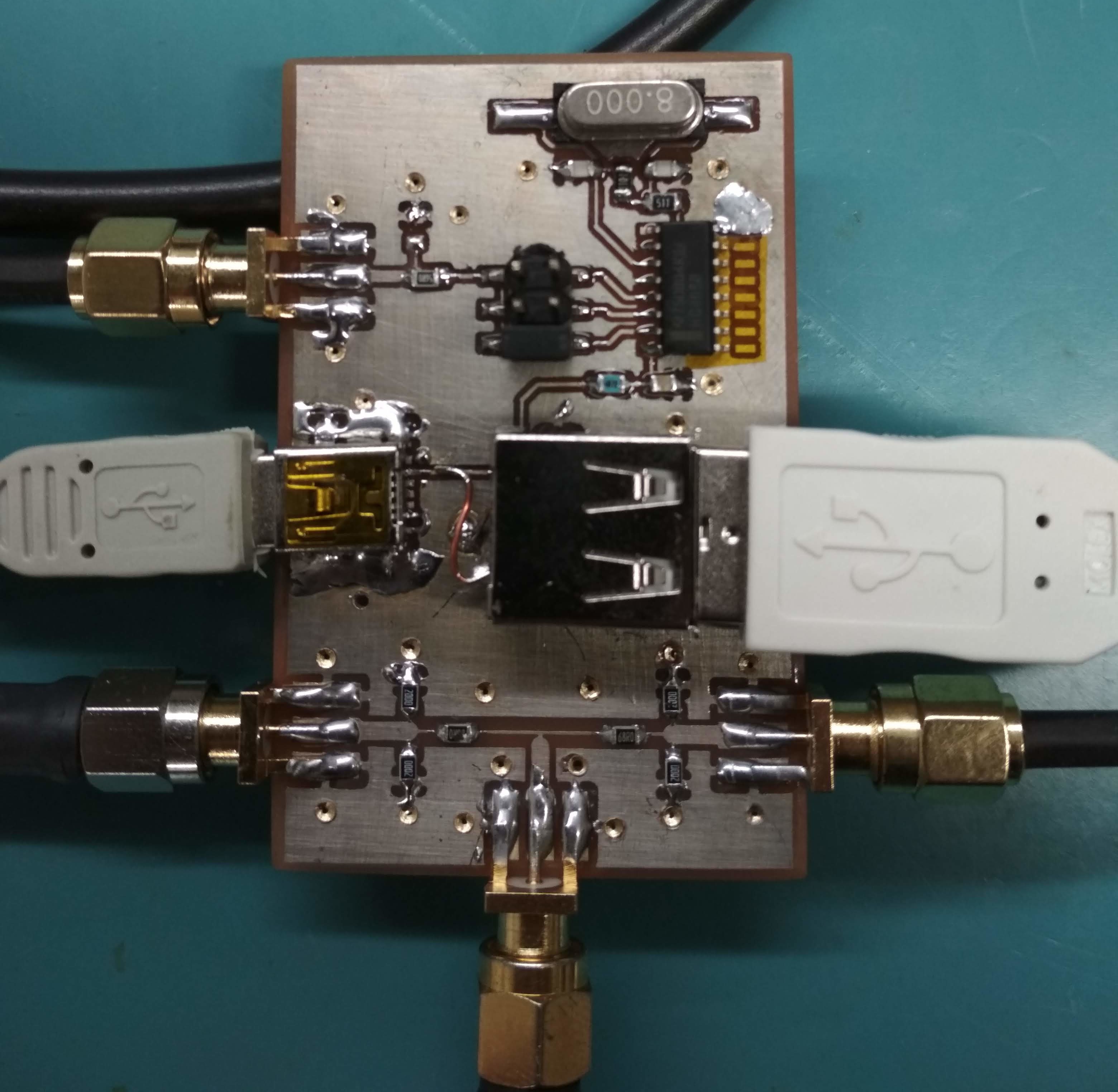
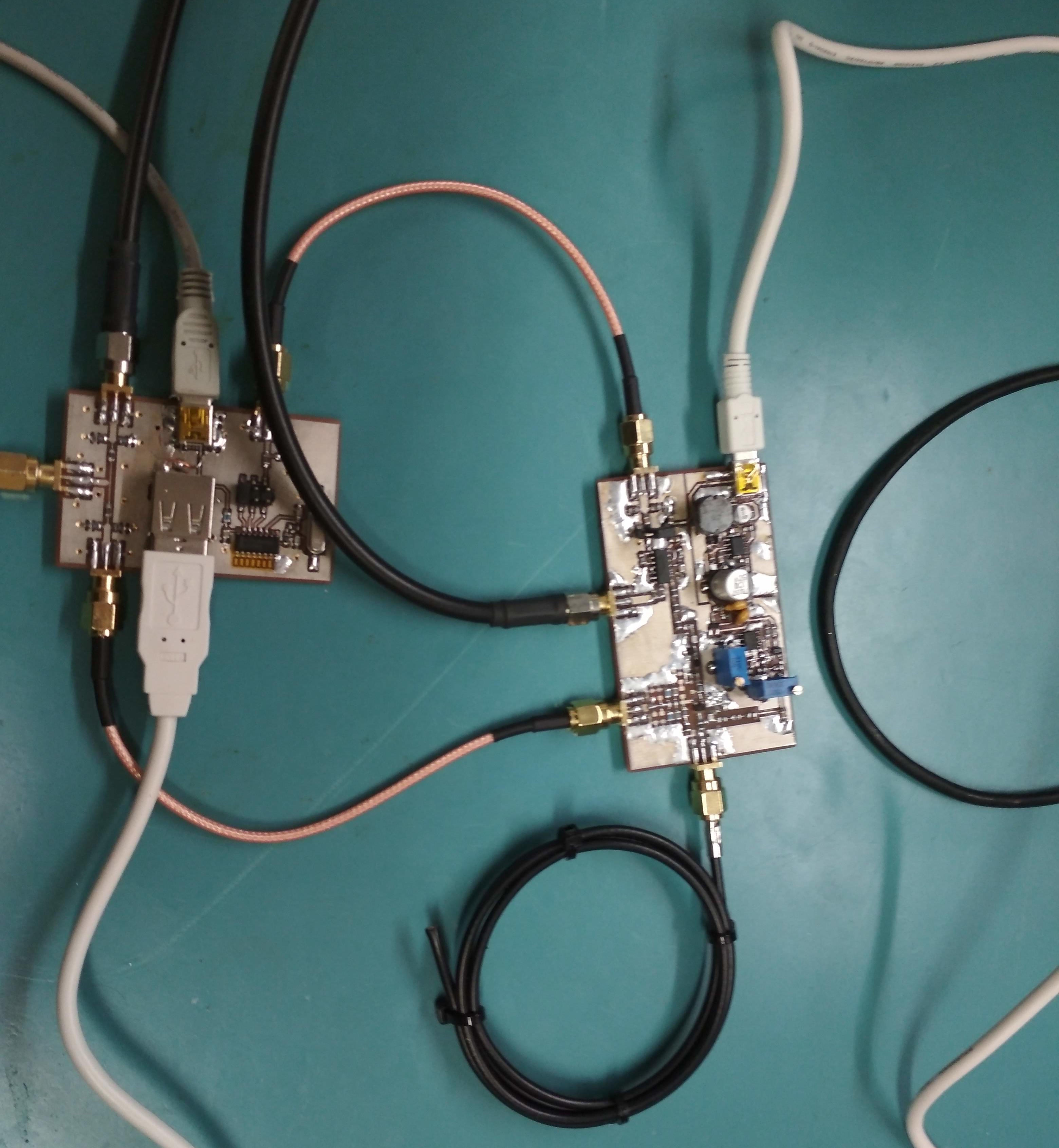
Closeup of the assembled board with all cables connected (please note that the bad IC footprint is already corrected)
Both the avalanche pulse generator and splitter connected:
Sidenotes
The PCB uses coplanar waveguide designed for use on standard 1.5 mm FR-4 substrate with 35 um copper (double-sided). It is not very carefully designed and does not give perfect match, but as a prototype, its performance was sufficient. You can modify it for whatever impedance you want, just follow this rule: connect parallel to each of the terminal ports resistor equal to 2x the load impedance, the series resistors should be 4/3x the load impedance and don't forget to update the coplanar waveguide according to the desired impedance.
 hesam.moshiri
 Just4Fun