 MS-BOSS
When I was designing this TDR, I was trying to avoid using expensive parts. Thus, ECL delay lines were out of question. I found a few articles which were using other ways to achieve equivalent-time sampling.
For example, there was a project which used two oscillators which were slightly out of tune. The problem was that it was highly "academic". The time step was dependent on the frequency of those two free-running oscillators, thus it depended on temperature, supply voltage and moon phase. Good idea, but not useable in such form. See the original article on IEEE XPlore (or look it up using SciHub or Library Genesis if you do not have access to scientific articles) A 16ps-resolution Random Equivalent Sampling circuit for TDR utilizing a Vernier time delay generation.
There were also several projects which used FPGA which implemented a DDS. This DDS generated a sinewave whose phase could be arbitrarily set in very small steps. Then this sinewave was turned into square wave. This way, the researchers were able to generate pulses for generating a pulse for the TDR and sampling pulses in one FPGA and a handful of components. The sampling was performed by a fast latchable comparator. In my opinion, this is the best architecture of TDR which I have seen in scientific articles, however I wanted to avoid FPGAs. See Miniaturized FPGA-Based High-Resolution Time-Domain Reflectometer
Then there was project which utilized D-type registers in the FPGA to directly store a train of pulses. Very imprecise, temperature dependent and needs a re-evaluation each time you generate bitstream for the FPGA (yuck). I hate non-deterministic digital circuits also, so this one was also out of question. See A Time Domain Reflectometer with 100 ps precision implemented in a cost-effective FPGA for the test of the KLOE-2 Inner Tracker readout anodes
Delay-line based reflectometers also turned up, however these are too expensive and too limited. See Sequential sampling time domain reflectometer
And then there was the usual bag of sh** which you can find in scientific articles, usually from universities which have to publish articles, even though they have nothing to show. This usually revolves around connecting pulse generator to oscilloscope, several pages of description of the splitter used for connecting together the generator, oscilloscope and DUT, then several pages covered in equations describing everything from Maxwell equations to the effect of solar eclipse on price of donuts after Easter 1919.
And so it seemed I had to come up with something new (almost). I was playing with dual-VCO PLLs Si5351 at the time, so I thought if I could use them for this purpose. The answer was "probably yes, why not try it". And so I did. These PLLs allow you to set frequency of the two VCOs which can be non-integer. The fractional part allows the two frequencies to differ by less than 1 ppm. And the relation is precisely controlled as opposed to the "Vernier" article. So, nothing really new, just using newer and more interesting parts. When set to exactly 1 ppm difference in frequency, one can get one million of samples during one measurement cycle. I set the measurement cycle to 10 microseconds so it could be easily measured by internal ADC of STM32 microcontroller. This gives the ability to measure 1 million of samples 10 picosecond apart.
The frequency of the two VCOs is below, parameters a, b and c are the integer and fractional part of multiplier, d is the divider.
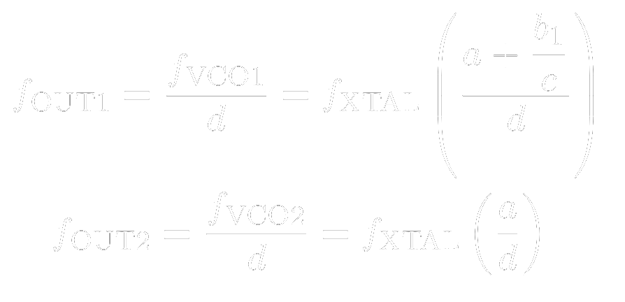
The time step of sampling is then given by the next equation:
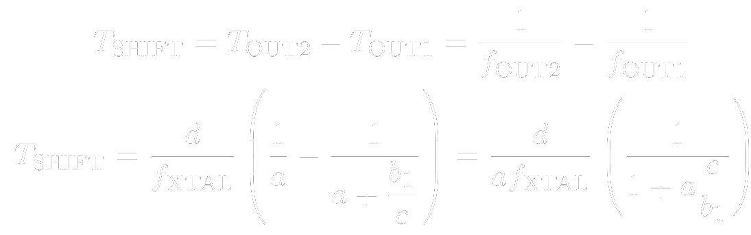
From these equations, you can find out how to set the parameters to suit your needs (time step, number of points, measurement length).
Discussions
Become a Hackaday.io Member
Create an account to leave a comment. Already have an account? Log In.