 Grant Giesbrecht
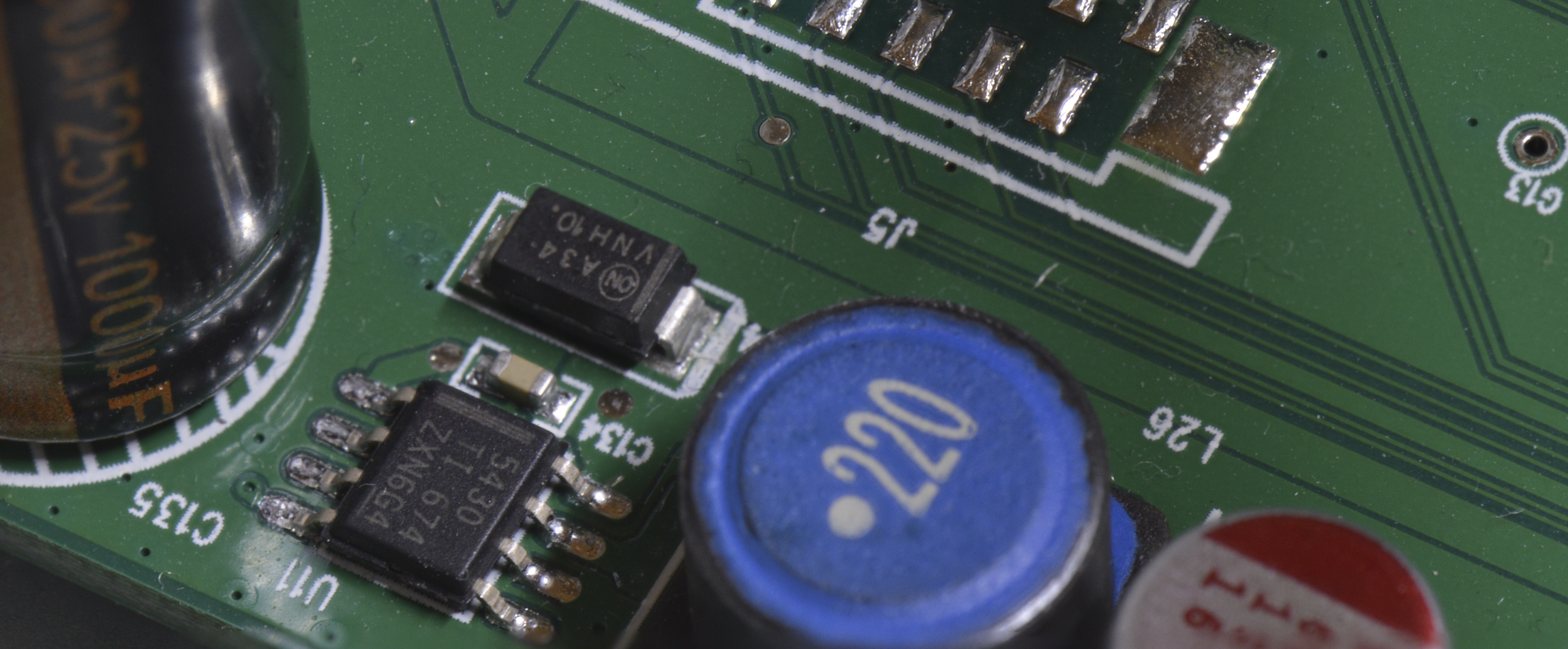
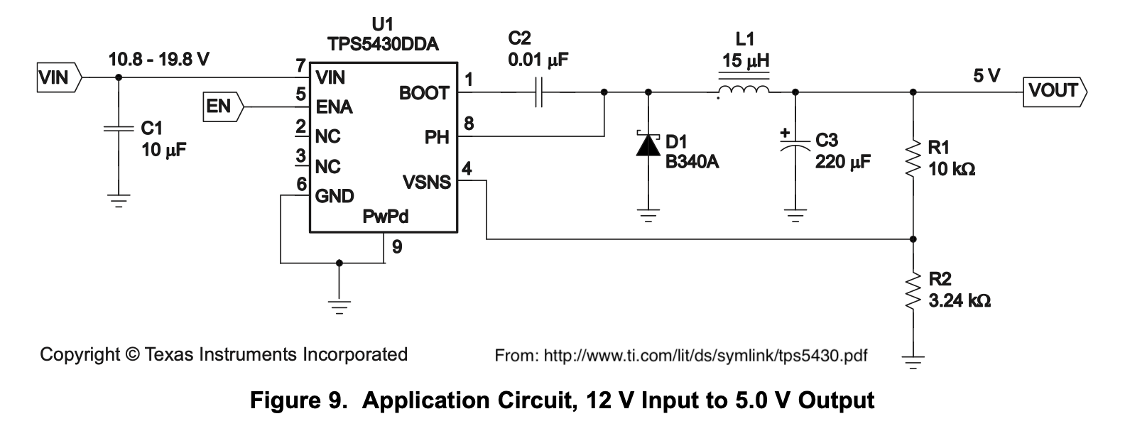
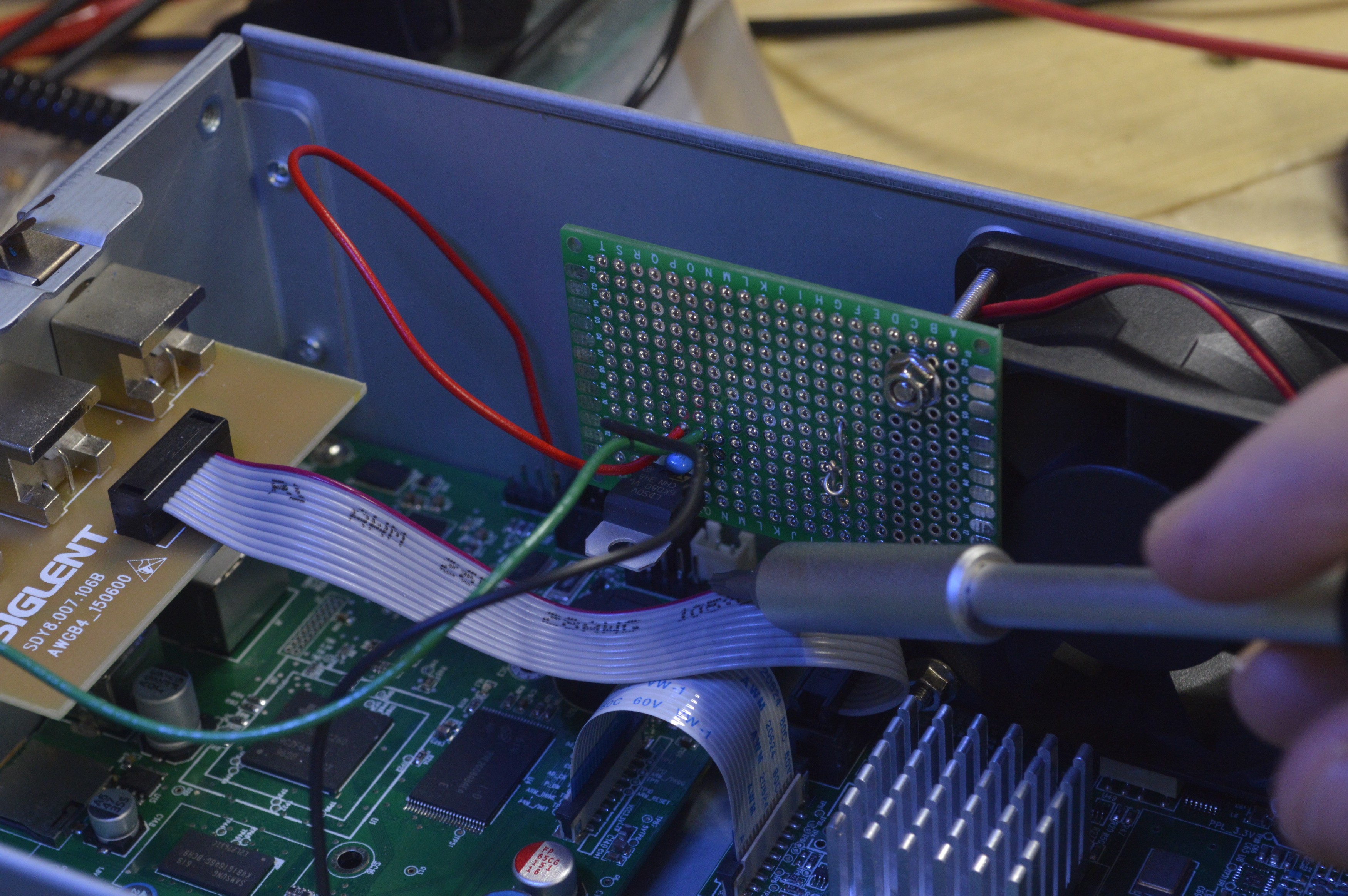
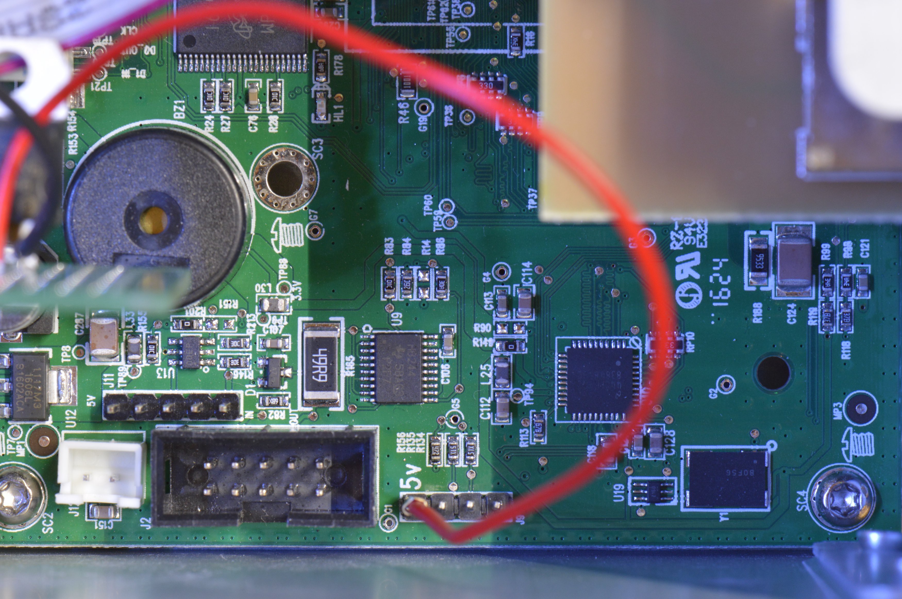
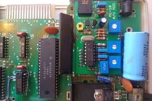
If you want more details on what exactly failed in my machine, the circuit for the 5V supply, how I fixed it, etc let me know in a comment below.
0%
0%
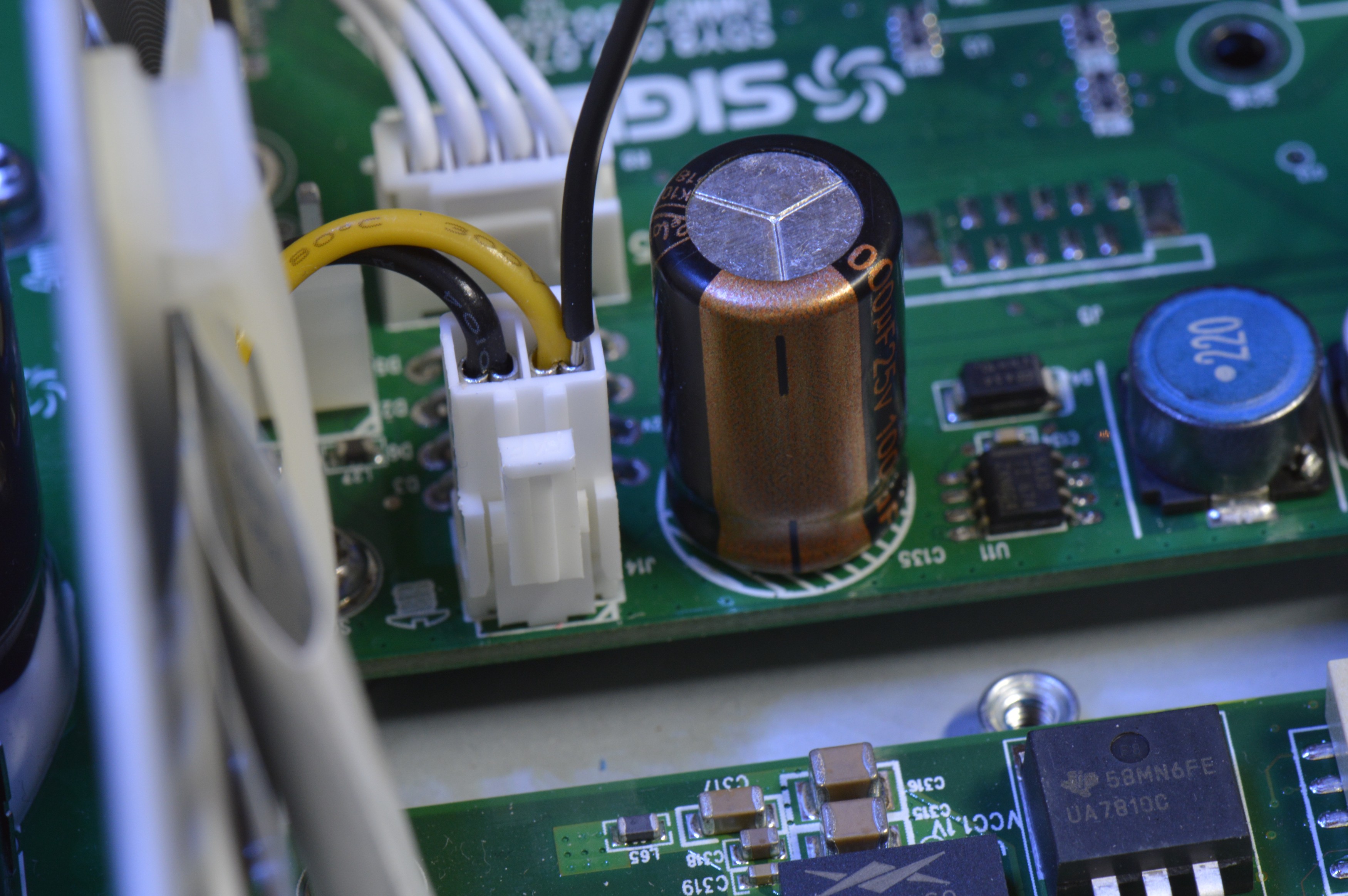
SDG2042X Repair
My waveform generator gave up the ghost, I fixed it with a homemade mod board
Become a Hackaday.io member
Already have an account? Log in.
Just one more thing
To make the experience fit your profile, pick a username and tell us what interests you.
Pick an awesome username
hackaday.io/
Your profile's URL: hackaday.io/username. Max 25 alphanumeric characters.
Pick a few interests
Projects that share your interests
People that share your interests


 danjovic
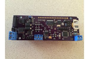
 Nick Sayer
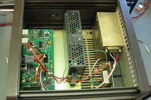
 Quinn
Quinn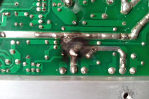
 ric866
Oh yes, please - I'd love to hear more details on this fix. How old was the unit when it died?