Abstract
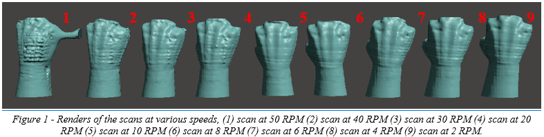
The goal of this study is to find the optimal scanning speed for the best scan accuracy when using a low-cost scanner. This will be accomplished by using a Sense™ 3D Scanner as the low-cost scanner in this pilot study. Each iteration of the tests increases the RPM of the stepper motor driving the 3D scanner arm and the resultant mesh is post-processed in the scanner’s software and exported to an OBJ format for the comparison metrics. The result of these tests showed that a scanning speed of eight RPM at a distance of six inches was an optimal scanning speed and distance when using a Sense™ 3D Scanner. These results can be used for inference when creating a new three-dimensional scanning unit.
Introduction
The digitization of an amputee’s residual limb has become a crucial step to prosthetic and orthotic socket design, which leads to investigations into where the resolution of the scan versus of the cost of the scanner can be maximized [1], [5], [7]. In addition, stable platforms for the creation of the scan need to be implemented that are repeatable and reliable to ensure the same scan quality every time as this will allow for repeatable socket quality [4], [6]. To fabricate a comfortable socket that will cause less discomfort for a patient, an accurate scan is required to closely fit the socket [2], [3].
Common techniques to do this include using devices such as the Microsoft Kinect, the Creaform HandyScan, and the Sense™ 3D Scanner [5]. In addition to these devices, a protocol and apparatus is most likely needed to accurately and reliably perform the scan [6]. To this end, a custom 3D printed scanning apparatus is used along with a custom electronic control system so the scanning speed and the movement of the arm can be controlled [cite].
The purpose of this investigation is to experimentally find an optimal scanning speed that will create the best scan quality using a low-cost 3D scanner. In this study, a Sense™ 3D Scanner is used to this end along with a custom 3D scanner apparatus that can reliably move about the central axis of the scanned limb.
Methodology
Low Cost Scanner Implementation
The low-cost scanner being implemented in this study will be a Sense™ 3D Scanner, which prices at 499 USD as of the date of writing. This scanner, according to its specification sheet, is able to create scans with an accuracy of around 1mm with a resolution of 1mm [10]. The scan range covers between seven and seventy-two inches, but from our previous studies utilizing this scanner we have noticed that a distance of around twelve inches is ideal for limbs [cite]. Finally, the associated software for the scanner can output the scan into four formats: OBJ, WRL, STL, and PLY [10].
The scanning apparatus used for this study was a custom design that rotates about the limb’s central axis using a stepper motor and custom driving circuitry. This was shown in a previous study to create reproducible quality of scans and can complete a scan in only thirty seconds.
Simple Arduino Test Code
/*
 * Simple test code to perform scanning speed experiments
 * Original Copyright (C)2015-2017 Laurentiu Badea
 *
 * This file may be redistributed under the terms of the MIT license.
 * A copy of this license has been included with this distribution in the file LICENSE.
 */
#include <Arduino.h>
#include "BasicStepperDriver.h"

#define MOTOR_STEPS 200
#define RPM 10

#define MICROSTEPS 8

#define DIR 12
#define STEP 6
#define ENABLE 4
#define MS1 13
#define MS2 5
#define MS3 10

BasicStepperDriver stepper(MOTOR_STEPS, DIR, STEP, ENABLE);

void setup() {
  while(!Serial);
  pinMode(MS1, OUTPUT);
  pinMode(MS2, OUTPUT);
  pinMode(MS3, OUTPUT);
  digitalWrite(MS1, HIGH);
  digitalWrite(MS2, HIGH);
  digitalWrite(MS3, LOW);

  pinMode(8, OUTPUT); //RST
  pinMode(9, OUTPUT); //SLP
  digitalWrite(8, HIGH);
  digitalWrite(9, HIGH);
  stepper.begin(RPM, MICROSTEPS);
}

void loop() {
    /*
     * Moving motor to original position using steps
     */
    stepper.move(-5*(MOTOR_STEPS*MICROSTEPS));
    stepper.move(5*(MOTOR_STEPS*MICROSTEPS));
    while(1)
    {

    }
}
Results
Sense 3D Scans
Discussion
The 3D scanner arm utilized in this study has the potential to be a reliable platform for researchers in the study of socket design and prosthetic production. Additionally, the platform may have the capability to be used in the approximation of limb volume, which has implications in medical condition management such as in lymphedema [6], [8]. Due to the low-cost nature of the scanner and the apparatus that is used to rotate it about the limb’s axis, it is accessible to researchers looking to explore new ideas in this field.
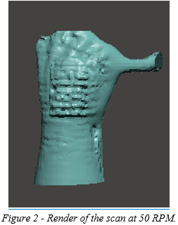
As can be seen in figure 2, as the scanner increases in scanning speed, there are artifacts that are captured. In addition, when using the Sense™ 3D Scanner, higher scanning speed can lead to loss of the software’s tracking fix, meaning that the scanner loses its place in the scan. These artifacts are also present in other scans as can be seen in figure X, so methods to remove these artifacts and acquire a cleaner scan should be explored.
Future studies have the potential to look at the scanner’s implementation in hybrid scanning systems, for instance using photogrammetry and laser scanning in parallel to reduce the deviation shown. By combining low-cost digitization strategies, the resolution of the resultant scan can increase and potentially match the limb volume accuracy of high-end scanners.
Acknowledgements
We would like to thank the Biomechanics Research Building at the University of Nebraska at Omaha for supporting this study with facilities and laboratory space to perform our experiments.
Funding Received
This research was supported by the NASA Nebraska Student Fellowship.
References
[1] Rosicky, Jiri, et al. “Application of 3D Scanning in Prosthetic and Orthotic Clinical Practice.” Proceedings of the 7th International Conference on 3D Body Scanning Technologies, Lugano, Switzerland, 30 Nov.-1 Dec. 2016, 2016, doi:10.15221/16.088.
[2] Krebs, D. E., Edelstein, J. E., & Thornby, M. A. (1991). Prosthetic management of children with limb deficiencies. Physical therapy, 71(12), 920-934.
[3] Jin, Yu-An, et al. “Additive Manufacturing of Custom Orthoses and Prostheses – A Review.” Procedia CIRP, vol. 36, 2015, pp. 199–204., doi:10.1016/j.procir.2015.02.125.
[4] Commean, P. K., Smith, K. E., & Vannier, M. W. (1996). Design of a 3-D surface scanner for lower limb prosthetics: a technical note. J Rehabil Res Dev, 33(3), 267-78.
[5] Comotti, Claudio, et al. “Low Cost 3D Scanners Along the Design of Lower Limb Prosthesis.” Proceedings of the 6th International Conference on 3D Body Scanning Technologies, Lugano, Switzerland, 27-28 October 2015, 2015, doi:10.15221/15.147.
[6] Buffa, Roberto, et al. “A New, Effective and Low-Cost Three-Dimensional Approach for the Estimation of Upper-Limb Volume.” Sensors, vol. 15, no. 6, 2015, pp. 12342–12357., doi:10.3390/s150612342.
[7] Koutny, D., Palousek, D., Koutecky, T., Zatocilova, A., Rosicky, J., & Janda, M. (2012, December). 3D digitalization of the human body for use in orthotics and prosthetics. In Proceedings of World Academy of Science, Engineering and Technology (No. 72, p. 1628). World Academy of Science, Engineering and Technology (WASET).
[8] McKinnon, J. G., Wong, V., Temple, W. J., Galbraith, C., Ferry, P., Clynch, G. S., & Clynch, C. (2007). Measurement of limb volume: laser scanning versus volume displacement. Journal of surgical oncology, 96(5), 381-388.
[9] Sanders, J. E., & Fatone, S. (2011). Residual limb volume change: systematic review of measurement and management. Journal of rehabilitation research and development, 48(8), 949.
[10] “Sense™3D Scanner.” 3D Systems, www.3dsystems.com/shop/sense/techspecs.
[11] Sanders, J. E., McLean, J. B., Cagle, J. C., Gardner, D. W., & Allyn, K. J. (2016). Computer-manufactured inserts for prosthetic sockets. Medical engineering & physics, 38(8), 801-806.
Discussions
Become a Hackaday.io Member
Create an account to leave a comment. Already have an account? Log In.