0%
0%
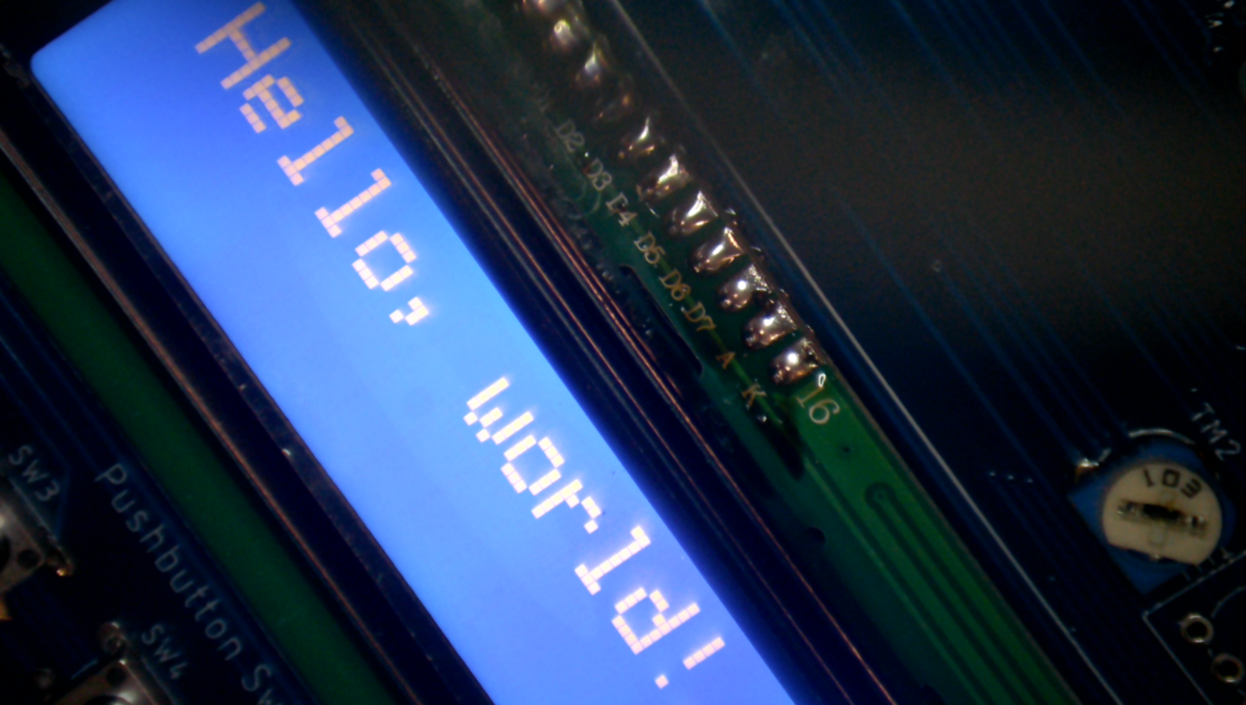
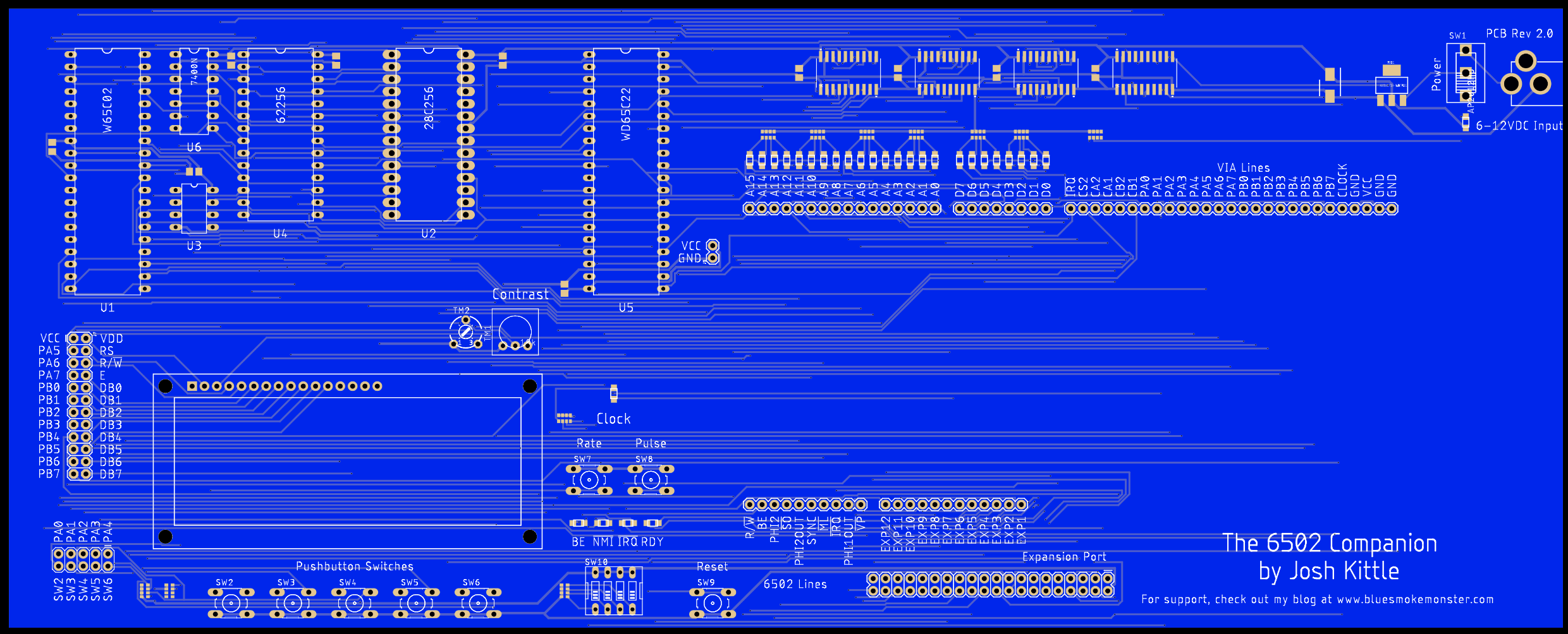
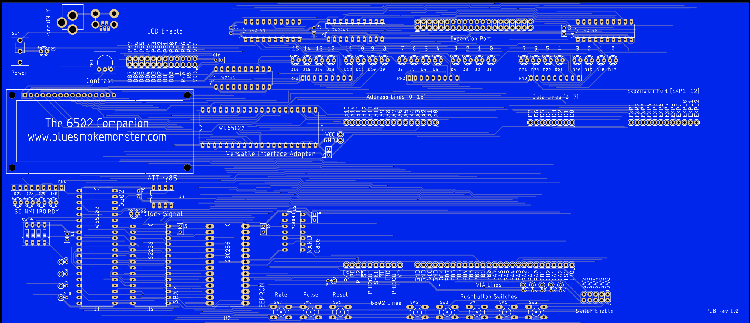
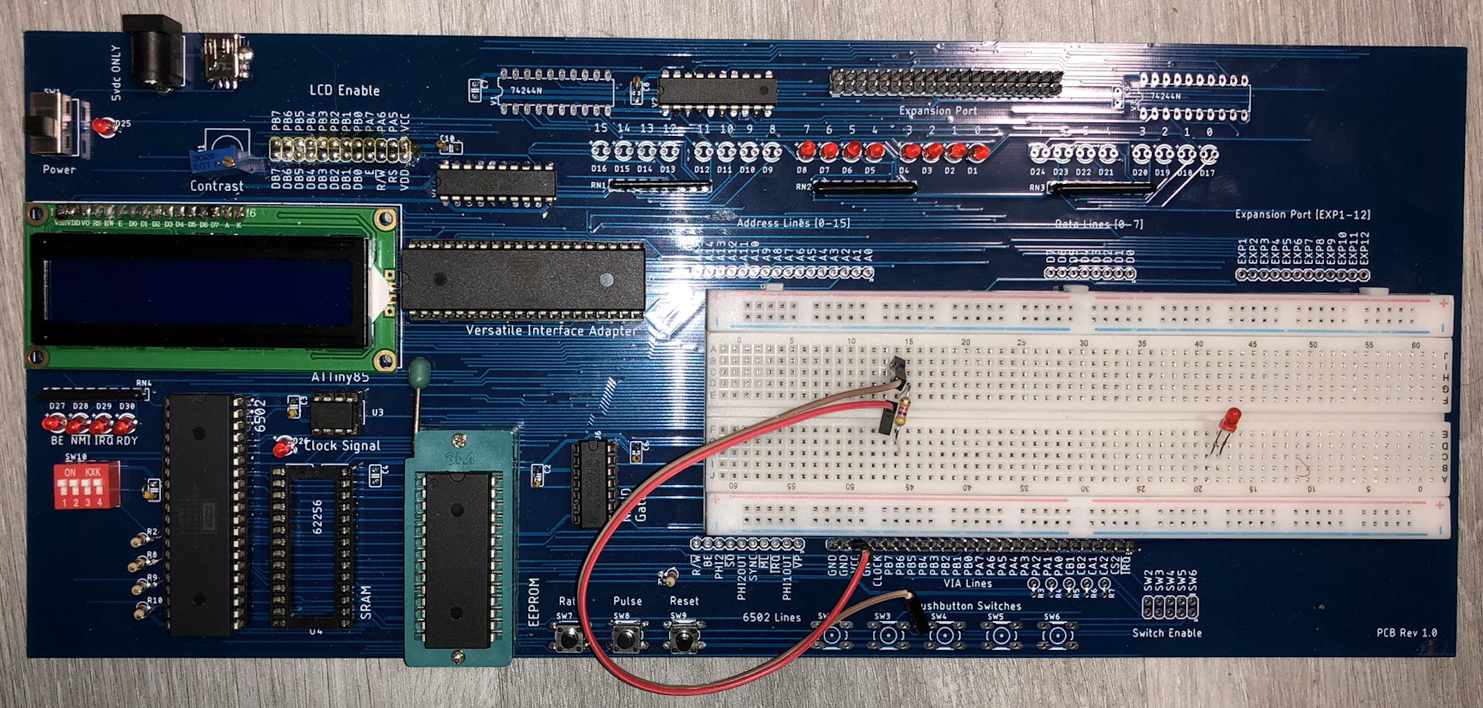
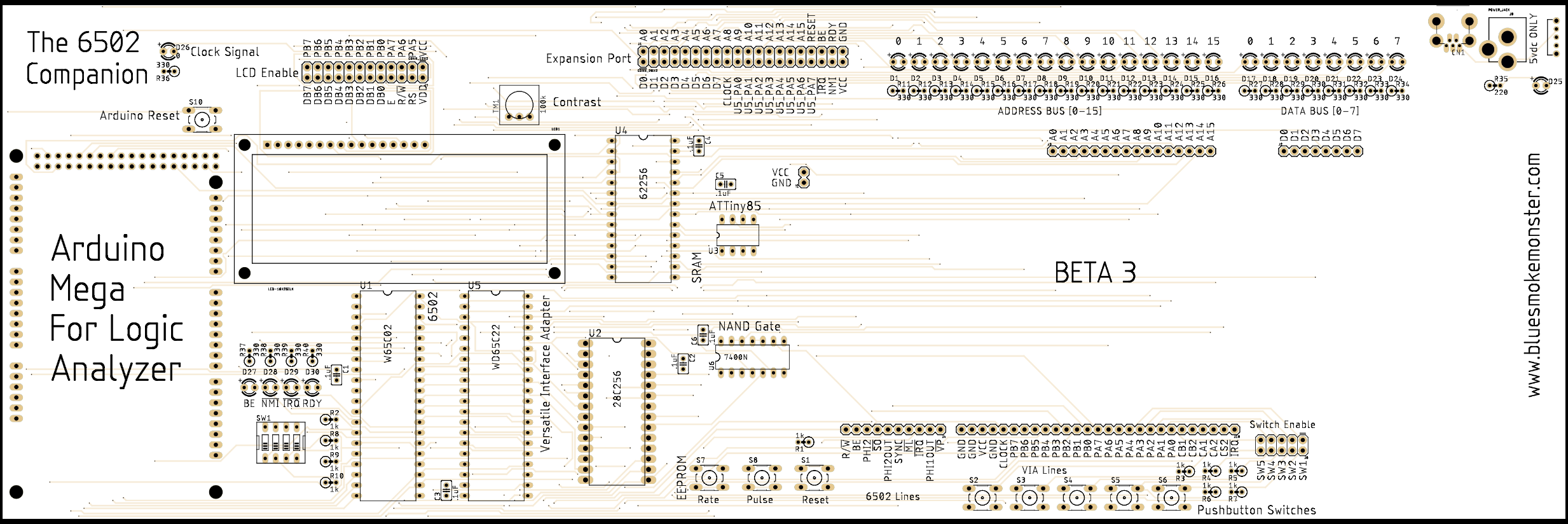
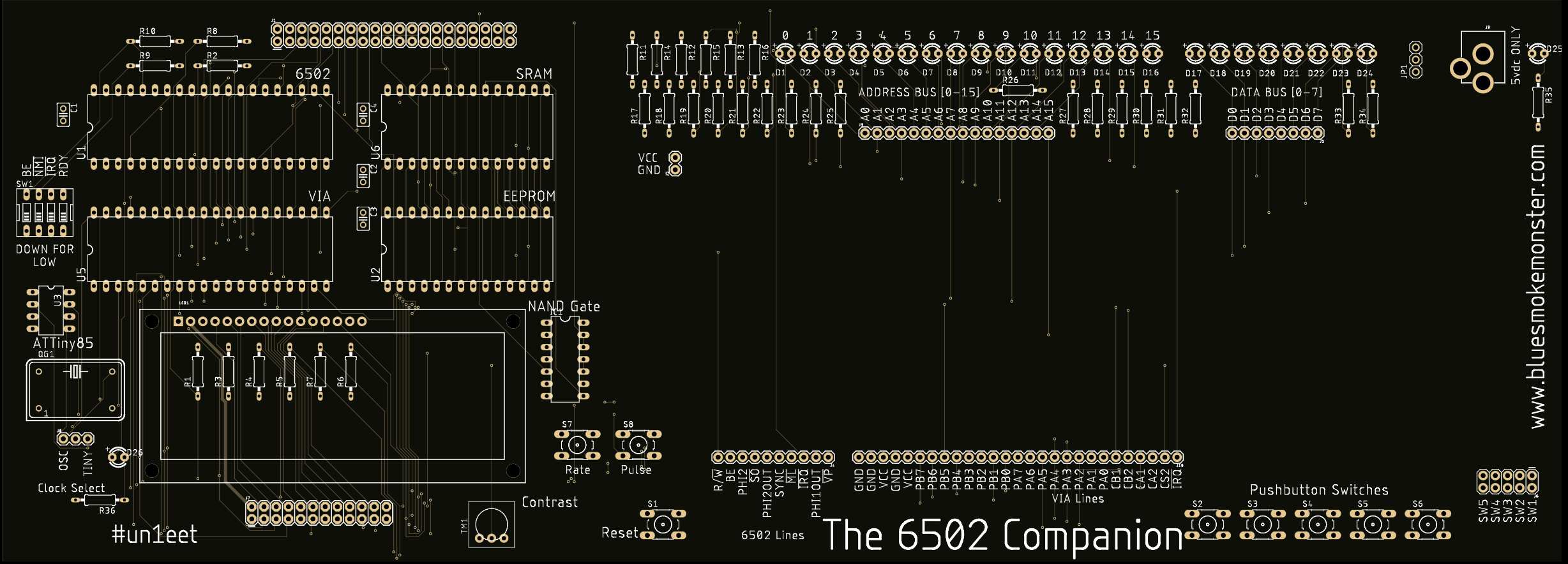
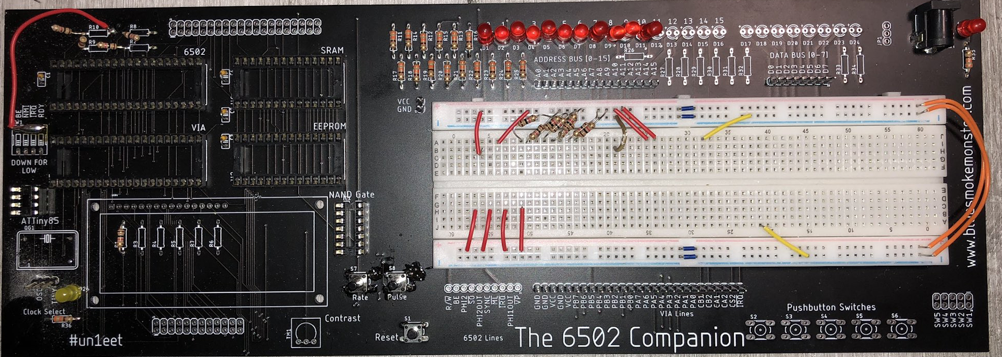
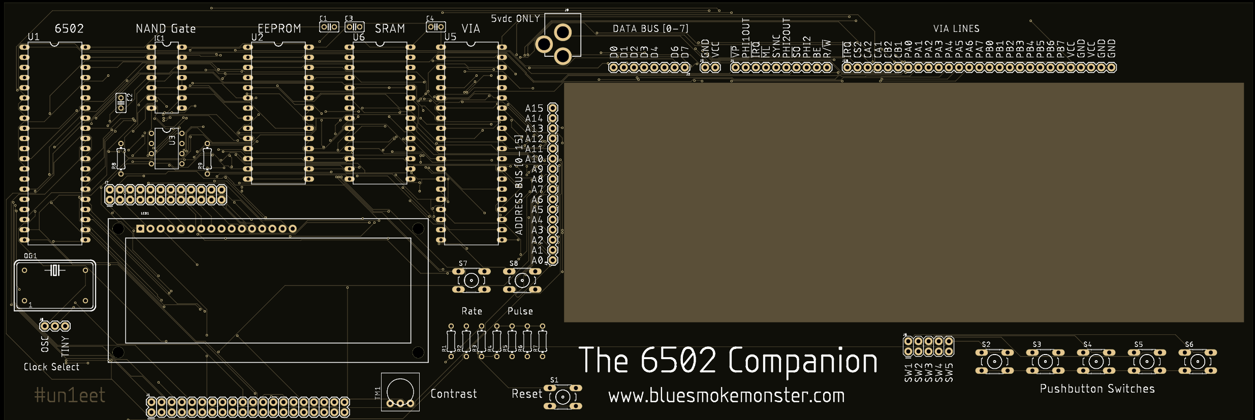
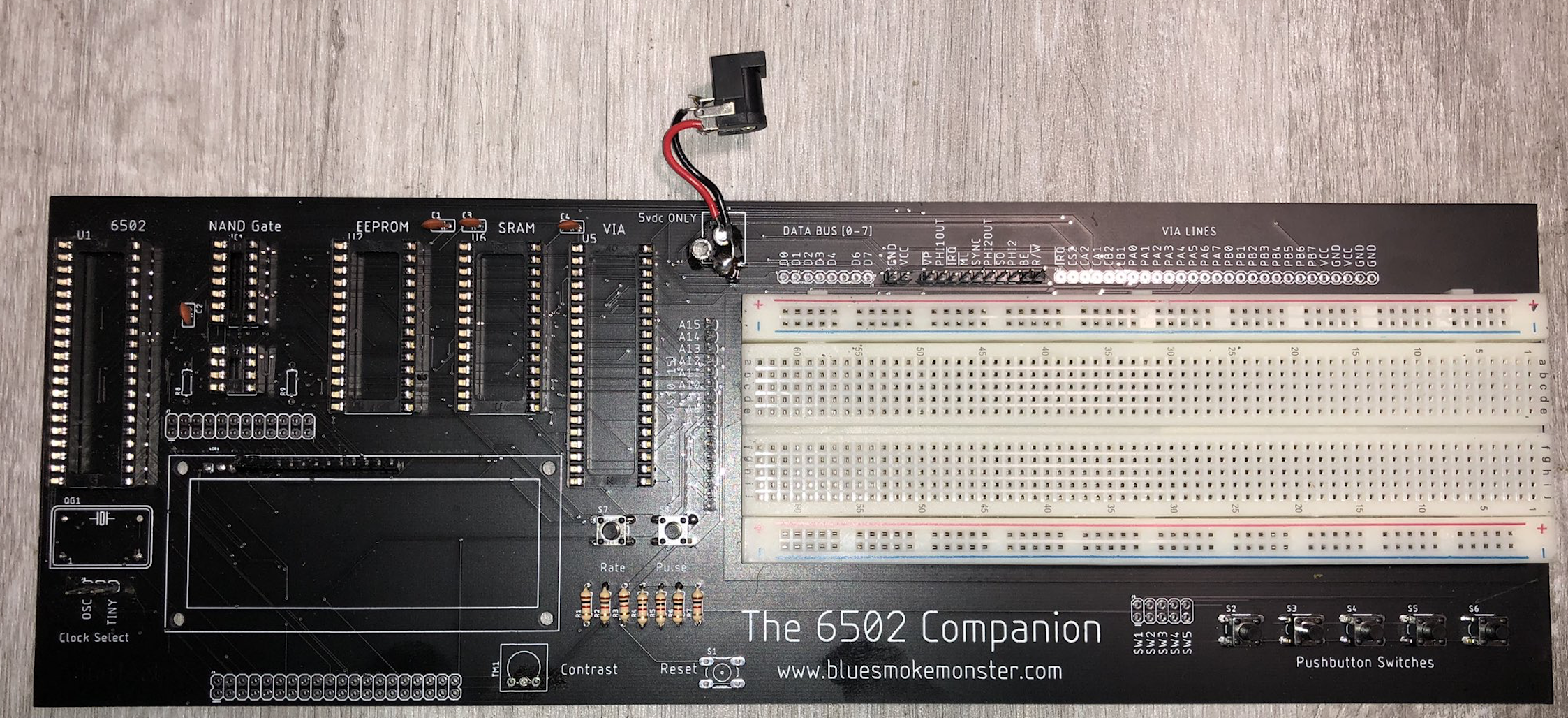
The 6502 Companion
The 6502 Companion is intended to be a development / learning environment for the 6502 microprocessor.
 Josh Kittle
Become a Hackaday.io member
Already have an account? Log in.
Just one more thing
To make the experience fit your profile, pick a username and tell us what interests you.
Pick an awesome username
hackaday.io/
Your profile's URL: hackaday.io/username. Max 25 alphanumeric characters.
Pick a few interests
Projects that share your interests
People that share your interests


 Dylan Brophy
 Michael Delaney
 Mike Teachman
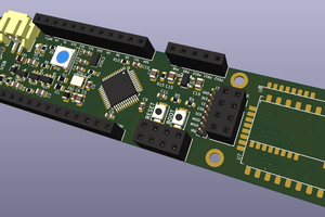
 Flavio
That board looks really cool in blue. I'm sure it will bring many hours of pottering joy to aficionados. I almost wish I had a history with the 6502 but my hardware contact was limited to the KIM-1, so I'm not really invested. Look forward to seeing more.