 Sophi Kravitz
Exploring an idea for a neuroscience application.
0%
0%
Tiny PCB weighing 2.5 grams w/ a few features
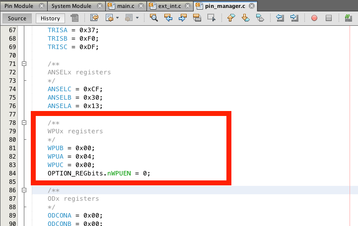
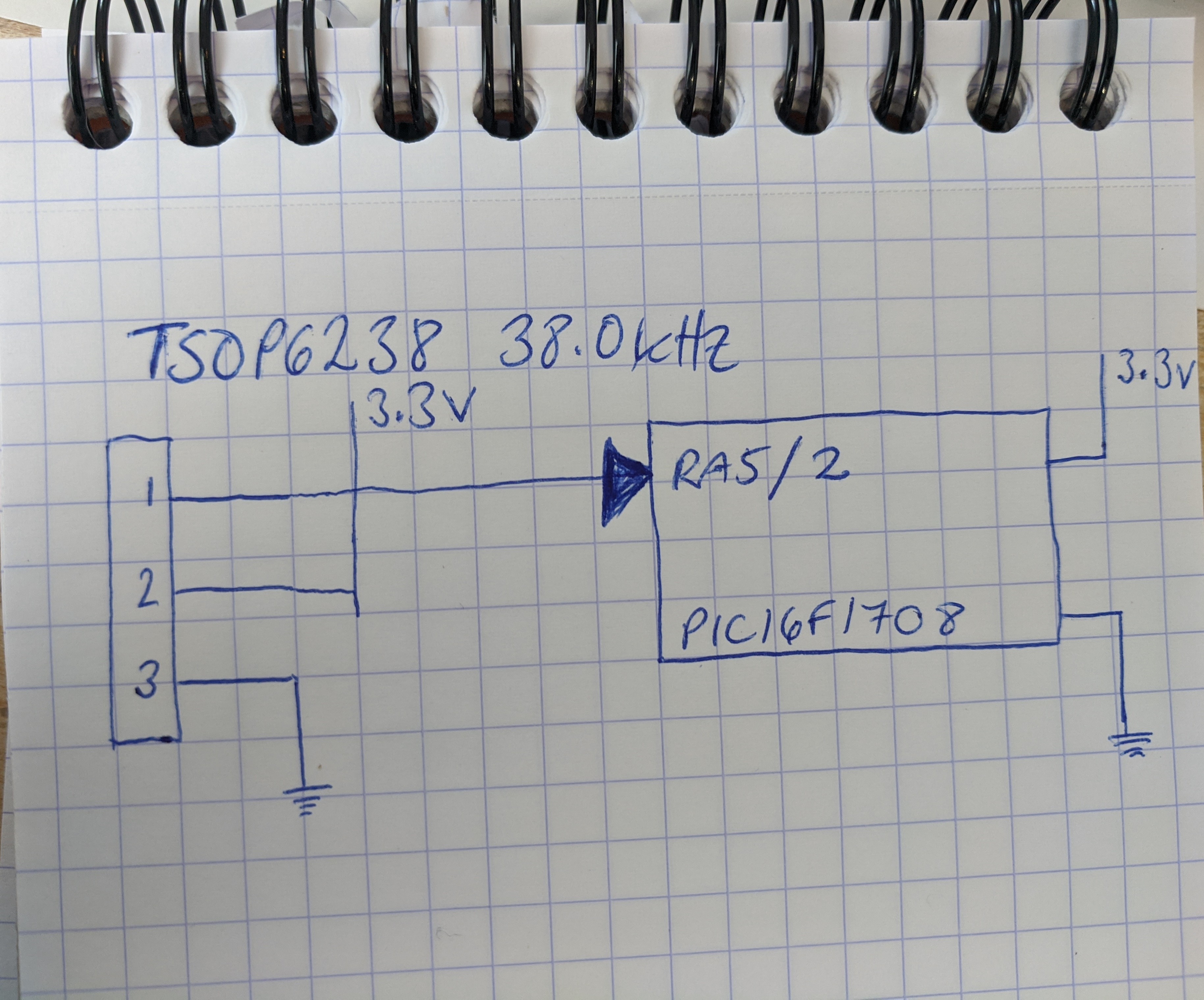
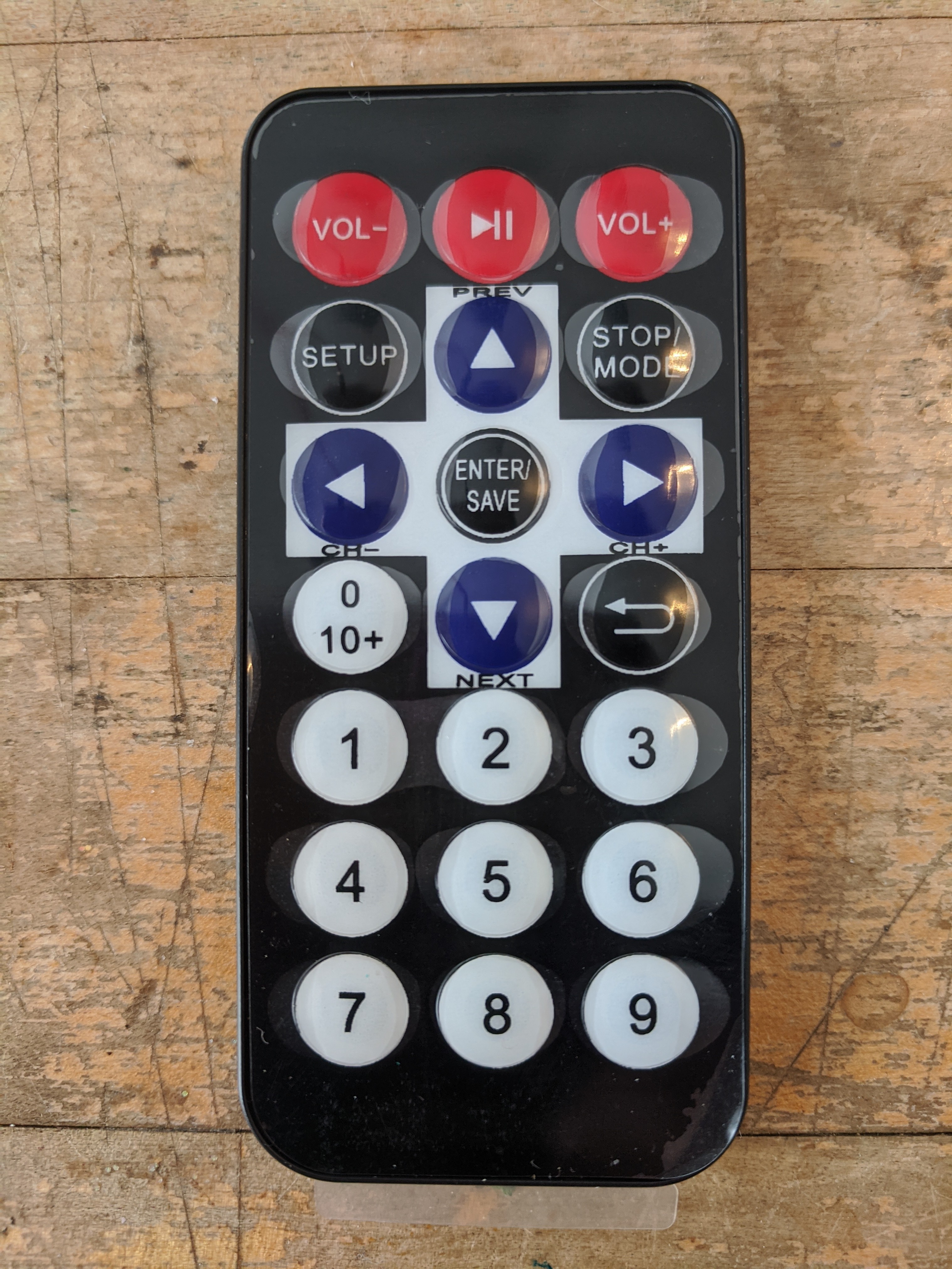
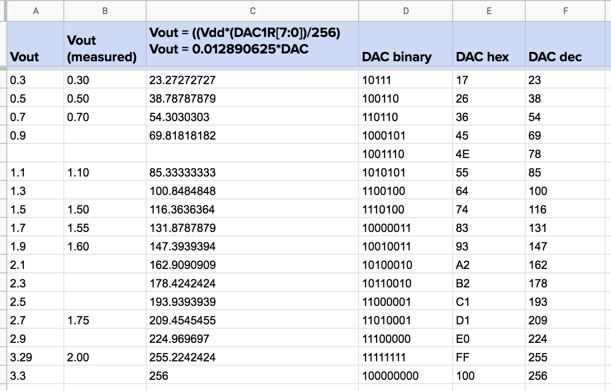
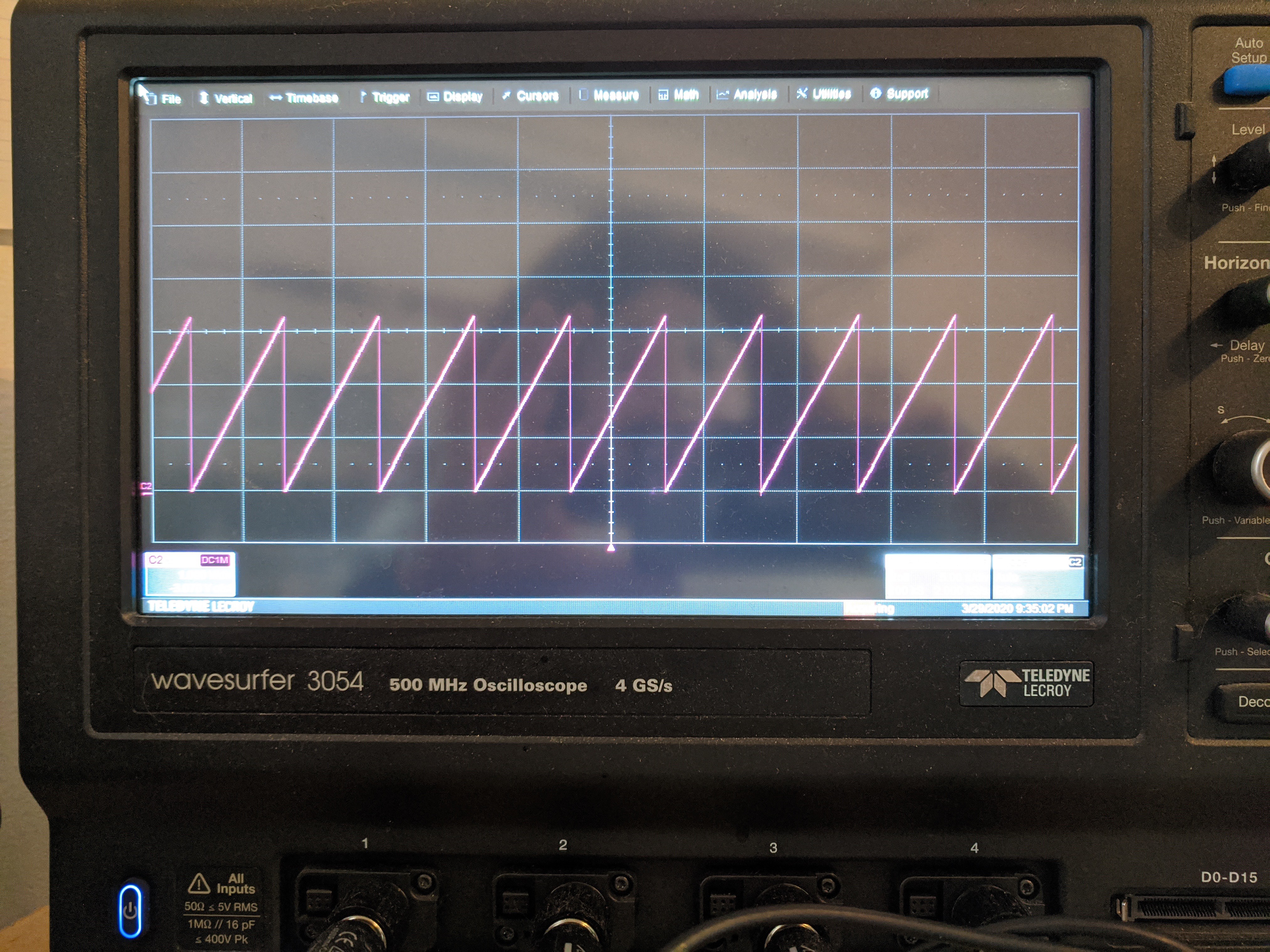
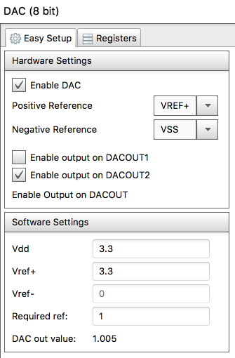
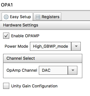
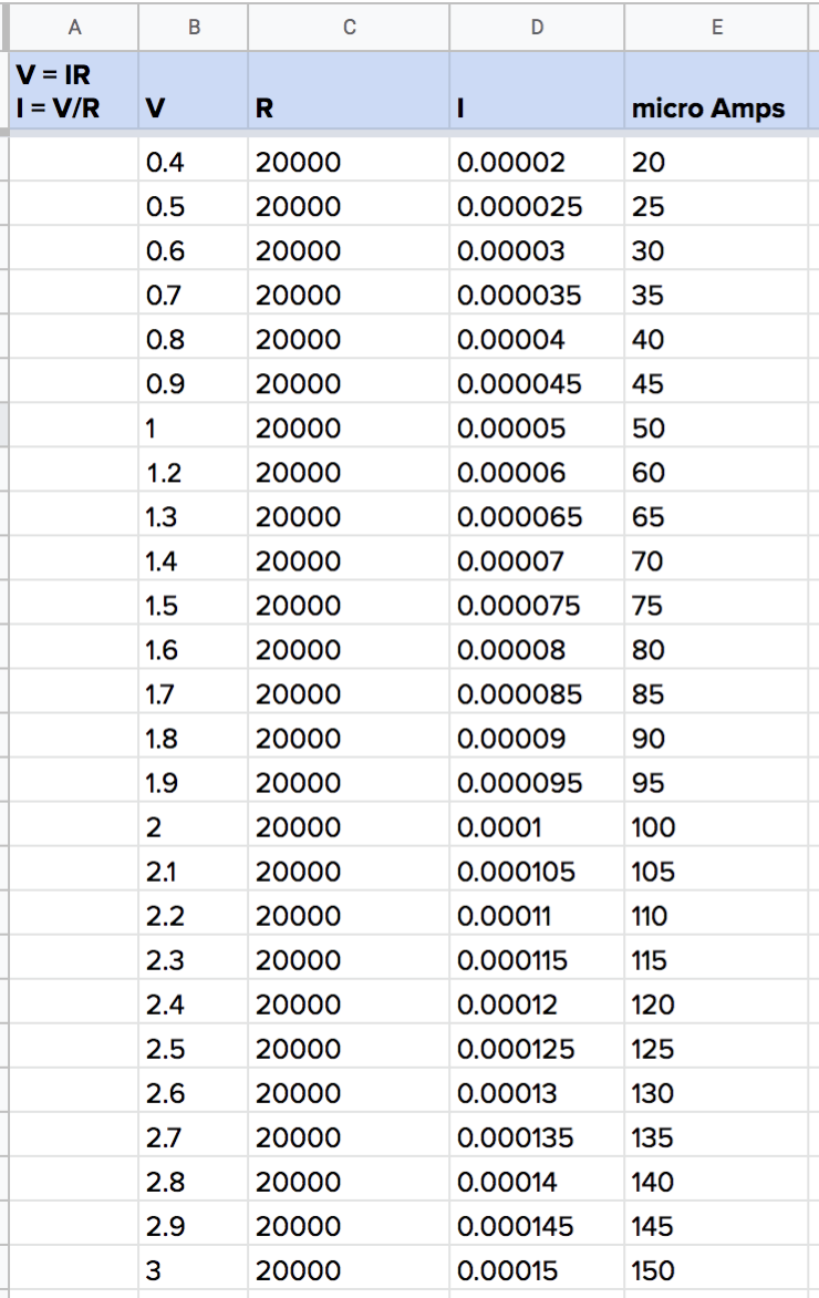
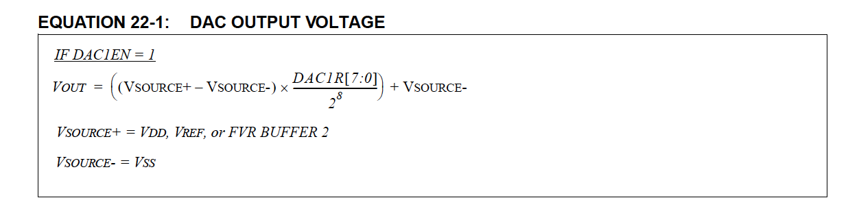
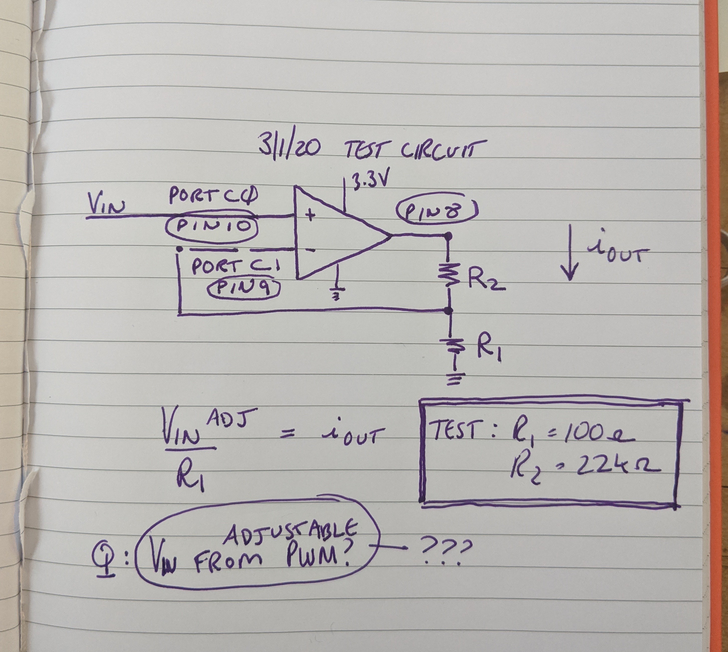
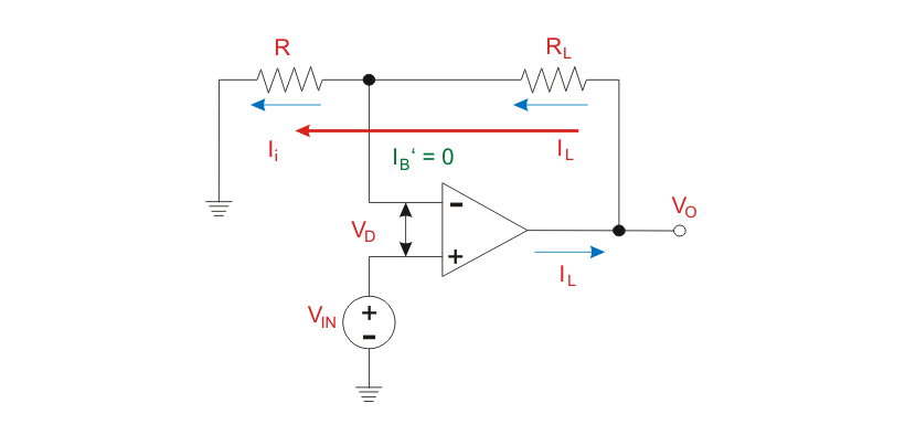
2 channel constant current programmable output, IR communications, weight < 3 grams
Become a Hackaday.io member
Already have an account? Log in.
Just one more thing
To make the experience fit your profile, pick a username and tell us what interests you.
Pick an awesome username
hackaday.io/
Your profile's URL: hackaday.io/username. Max 25 alphanumeric characters.
Pick a few interests
Projects that share your interests
People that share your interests
 Phil Wright
 Steven Gann
 Yann Guidon / YGDES