0%
0%
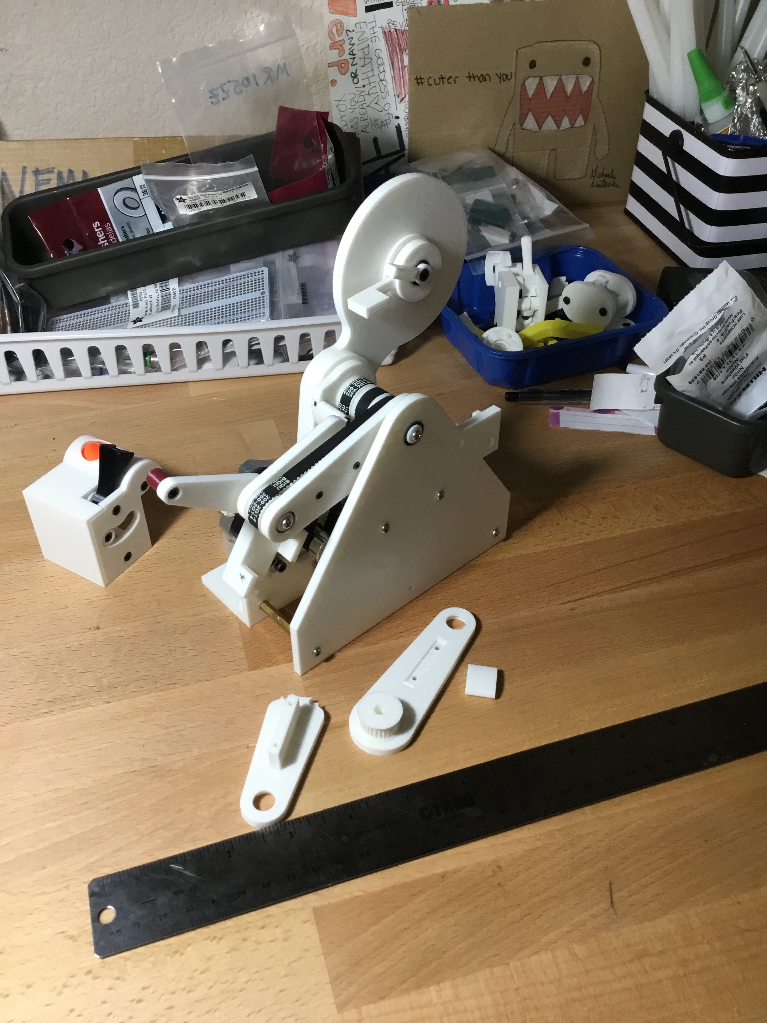
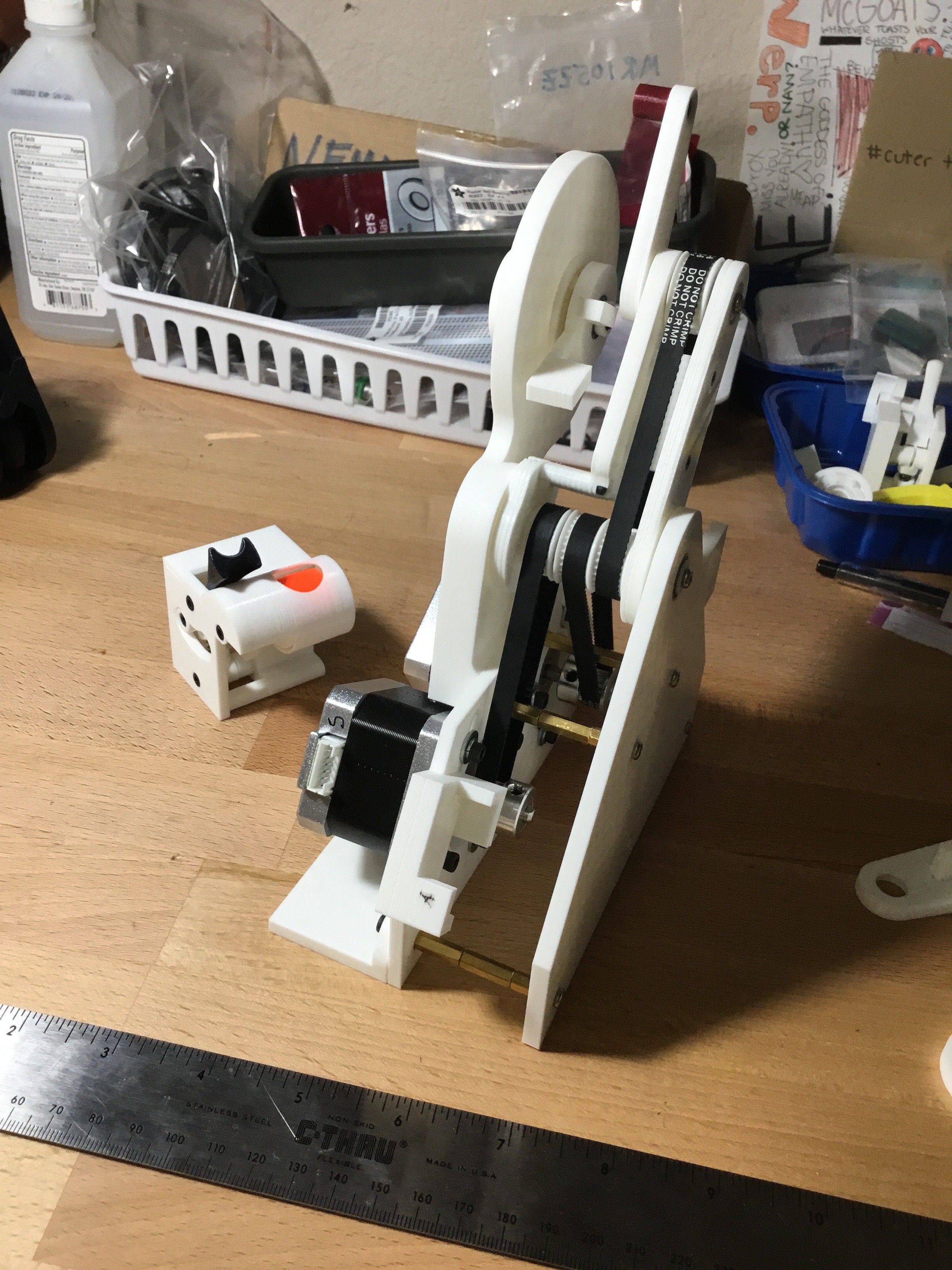
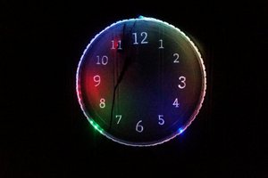
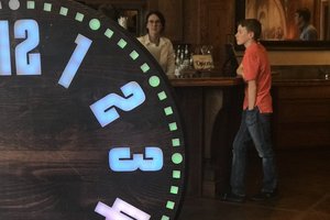
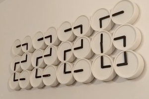
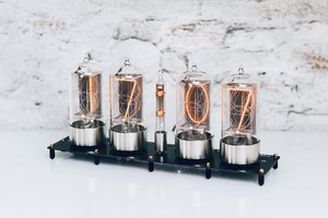
Temporal indicator: About every five minutes
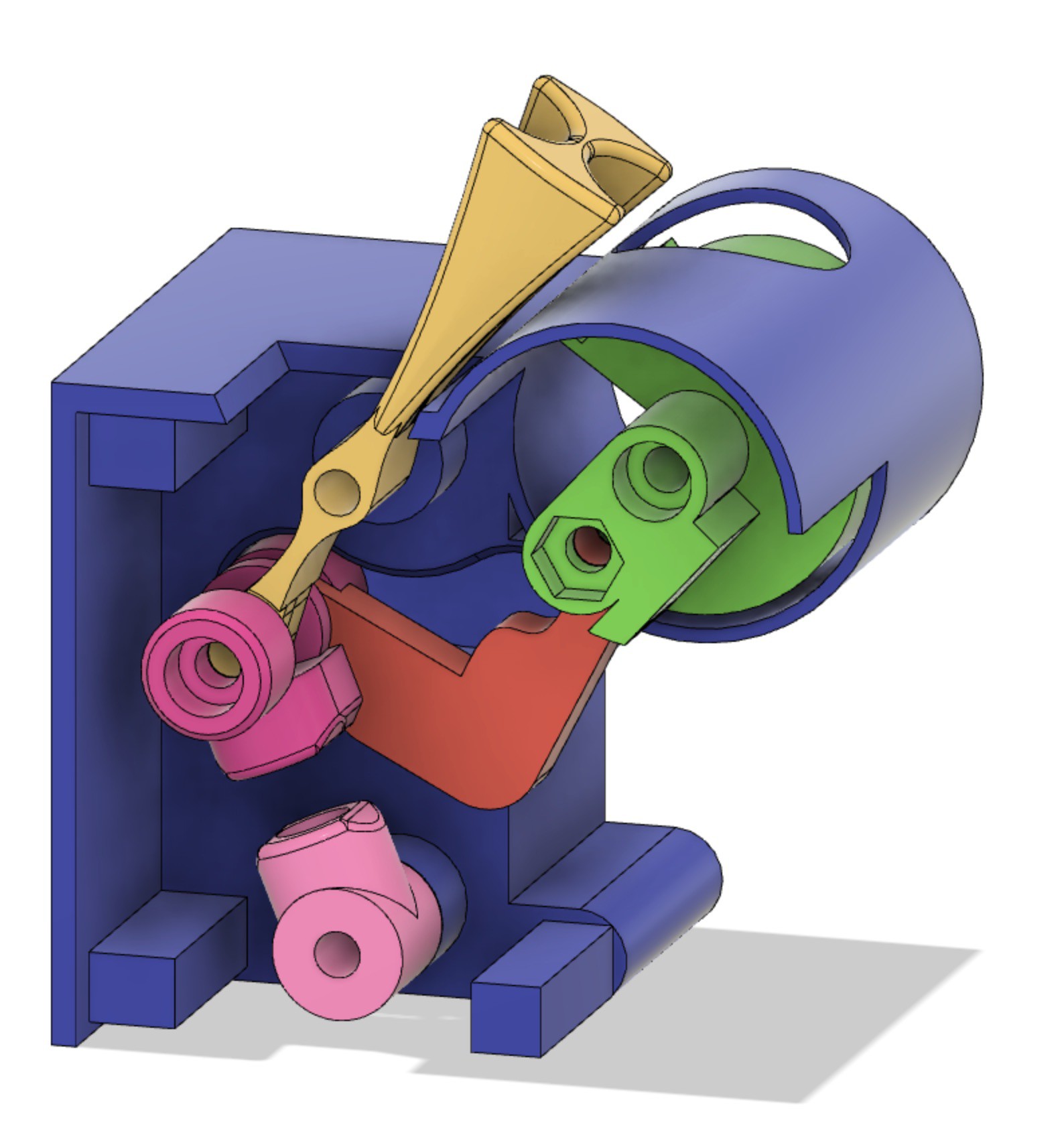
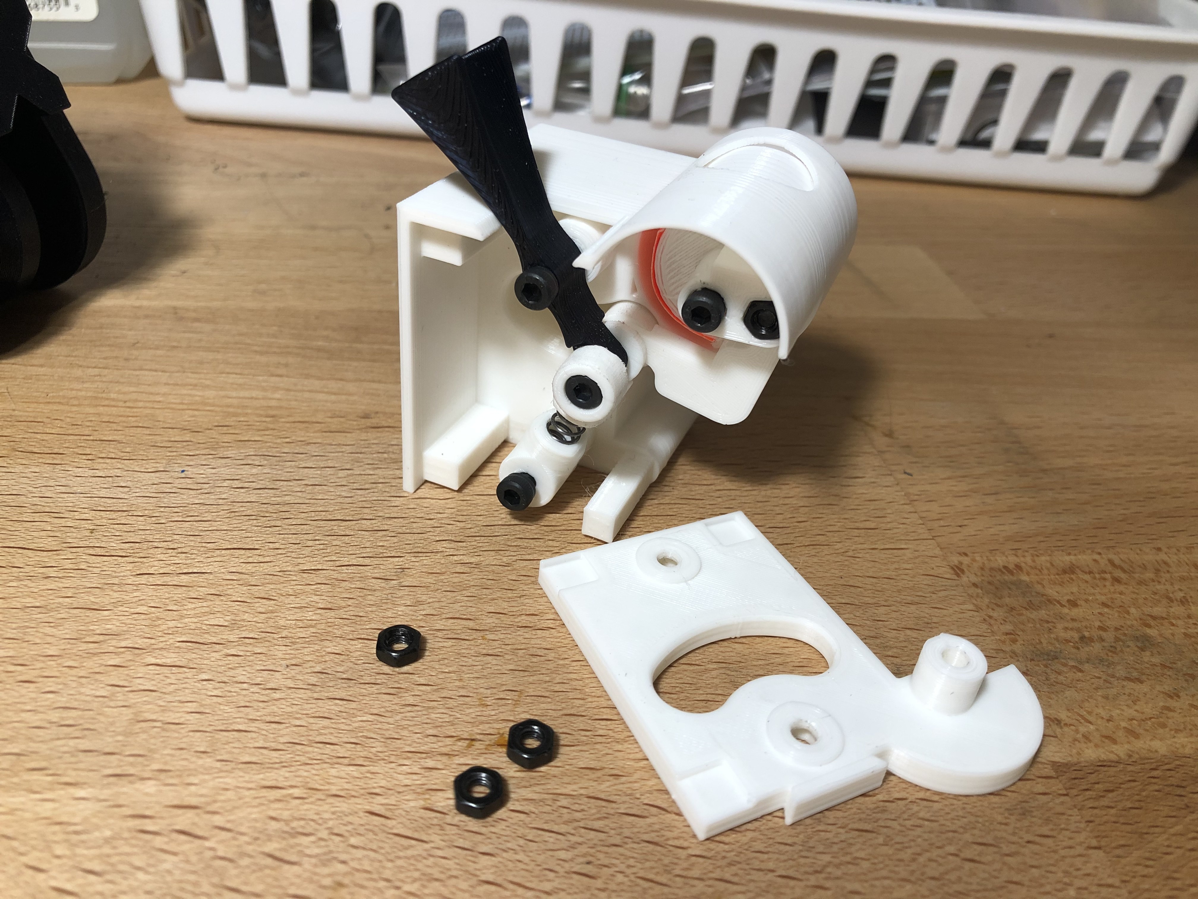
I call it a temporal indicator but you may call it a clock. Topics Learned: steppers, reverse kinematics, bimodality and friction.
 kmatch98
Become a Hackaday.io member
Already have an account? Log in.
Just one more thing
To make the experience fit your profile, pick a username and tell us what interests you.
Pick an awesome username
hackaday.io/
Your profile's URL: hackaday.io/username. Max 25 alphanumeric characters.
Pick a few interests
Projects that share your interests
People that share your interests


 Sebastian