 Andy
AndyThe board to design is really simple and straightforward. I'm going to put down a footprint for the MT25QL512ABB and an 0805 capacitor. The bottom will have the 2x4 1.27mm SMD female socket. Also by adding some 1x4 1.27mm pin header on each side this guy could double as a tiny general purpose MT25QL breakout. The WPDFN-8 footprint is not included in the KiCAD library, but I already one that I had made from a project past. SnapEDA has one, but I've not tested it, so YMMV. All in all it's an incredibly easy board to lay out the only thing worth mentioning is that since the WPDFN-8 has a large EP pad on the bottom, I added a large via to that pad that will allow me to flow some solder under there to ensure a good thermal and electrical connection. The board is tiny and even with OSHPark's Super Swift service, it only costs 3.20USD delivered! Here's what the render of the board looks like:
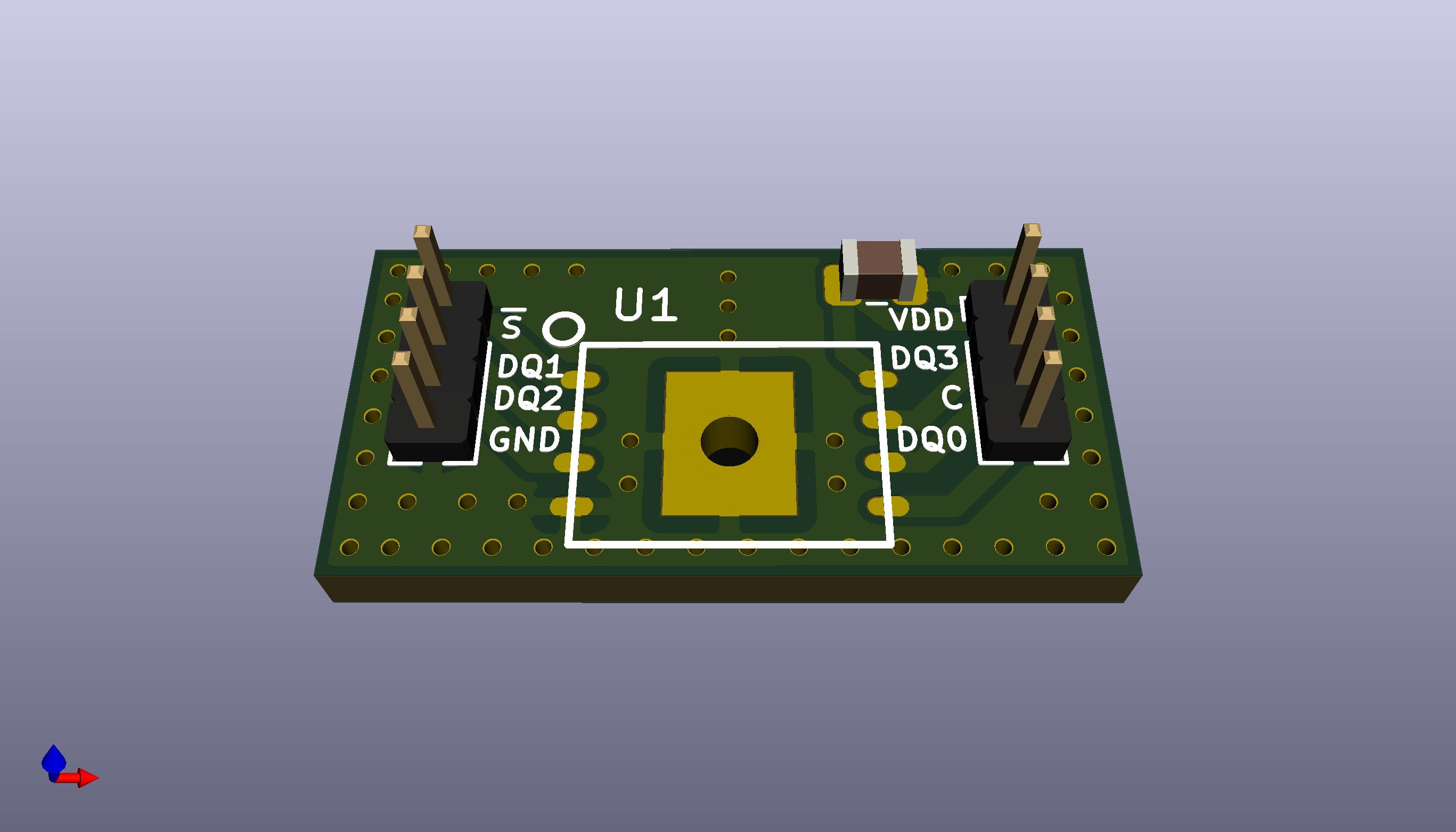
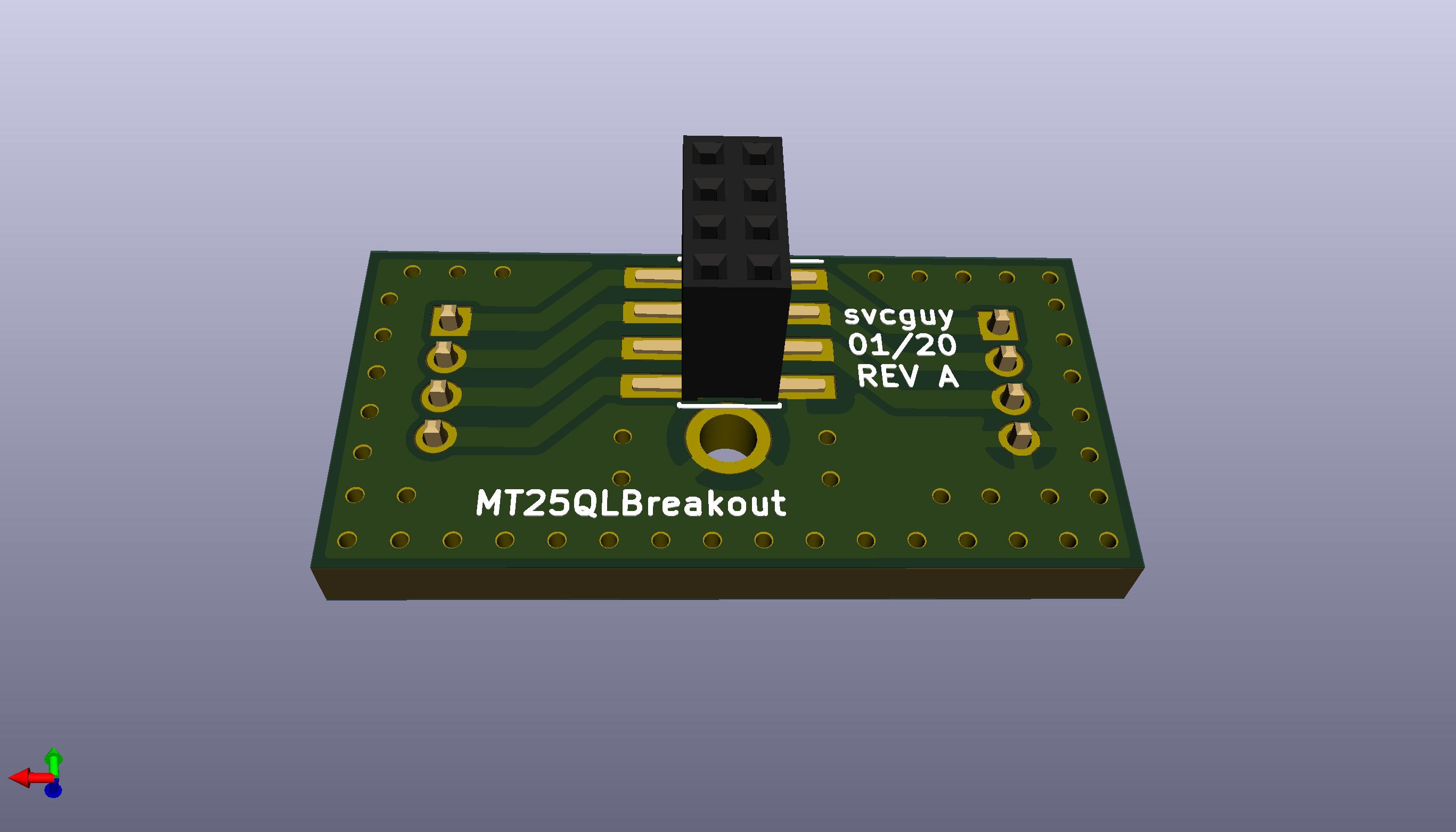
The Samtech female connector will be much shorter than pictured here.
Here's the BOM
U1 - MT25QL512ABB Digikey 557-1786-ND
C1 - 0805 0.1uF 16V X7R (any will do) (not strictly necessary)
J2 (bottom connector) - Digikey SAM13109CT-ND
J1, J3 (top pin header) - Digikey 952-3600-ND (not necessary)
Mating connector for J2 - Digikey SAM13898CT-ND
Here's the board file on OSHPark:
Next up, build it when everything comes in!
Discussions
Become a Hackaday.io Member
Create an account to leave a comment. Already have an account? Log In.