Close
0%
0%

Racing Spider

Flexapod (Servo-less Octapod)

Public Chat
Similar projects worth following
A playfully terrifying mechanical spider with a unique drive system

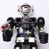
I built this for the challenge, I was inspired to improve upon the ideas that (former Mythbuster) Jamie Hyneman shared in his project videos from 2015. 

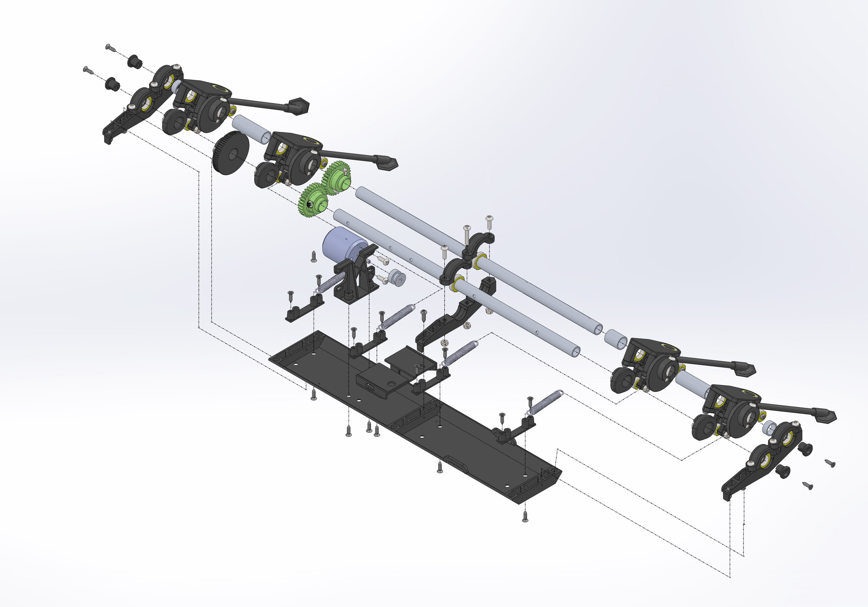
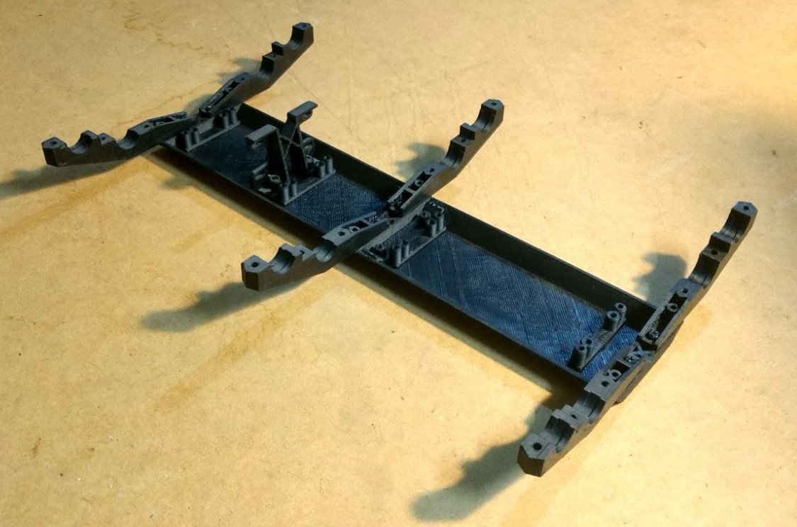
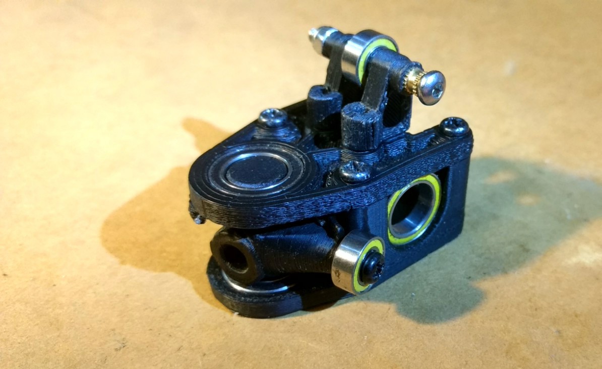
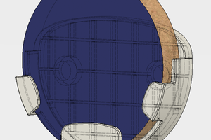
The key my version of his creepy crawly is what I'm calling a Flexapod mechanism. An Arrangement of cams, shafts and bearings that enables super radpid movement and adaptability over rough ground. Also it is quite capable of making people's skin crawl and squirm.

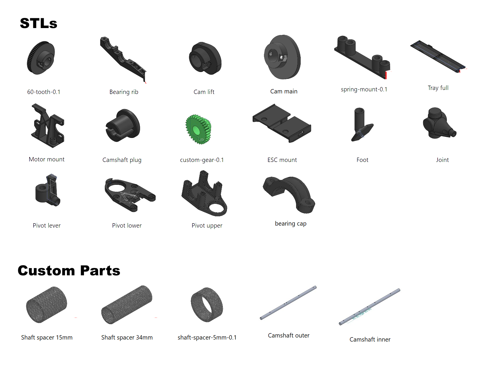
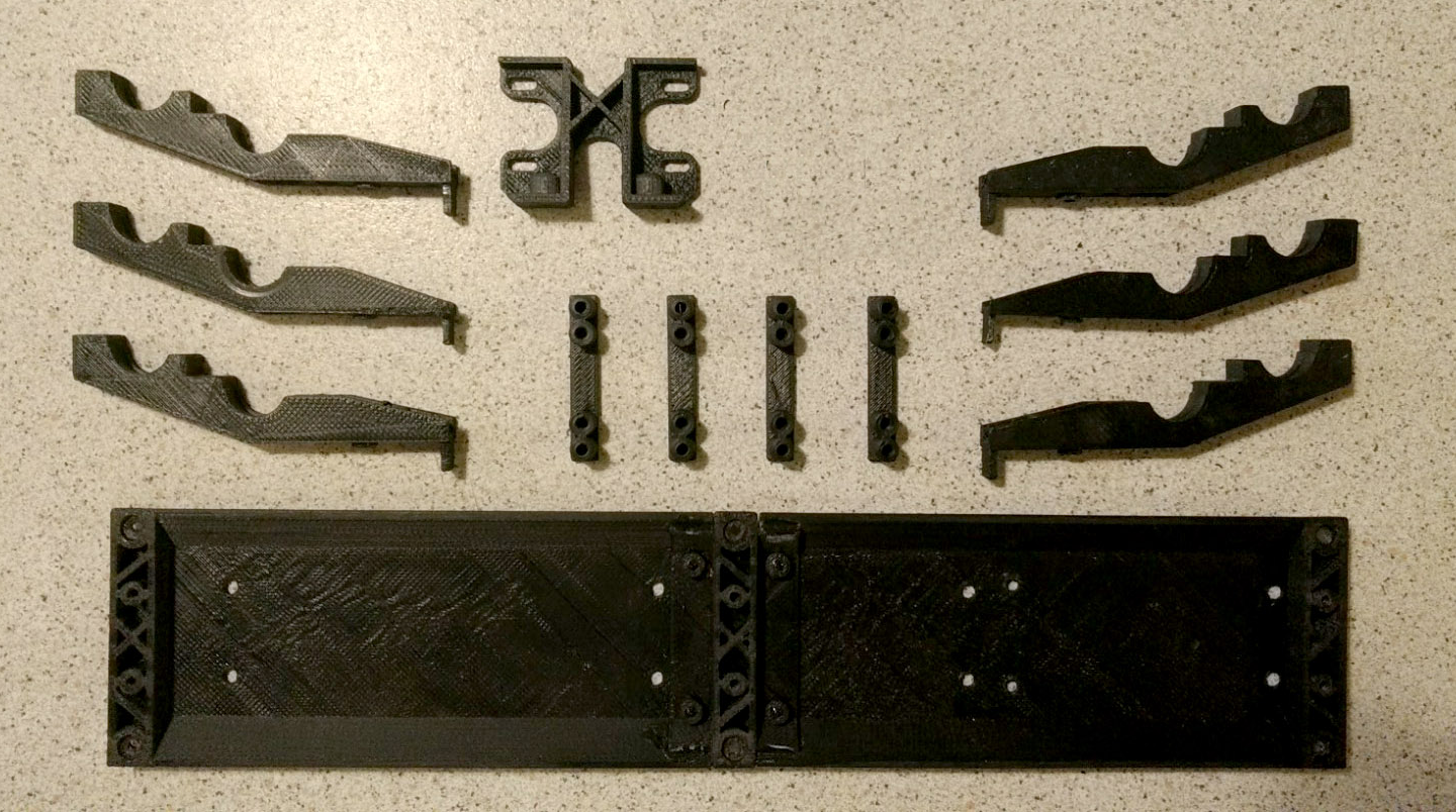
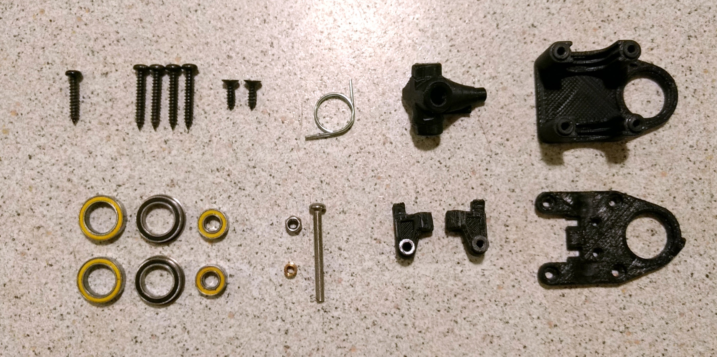
It uses 3D printing and off-the-shelf  RC parts: battery, bearings, motors, controllers, screws, bolts aswell as a few custom bits. All of which I will explain as I endeavour to share this project for those who want to build one of their own.

So if you keen to build it, let me know and I will help you where I can.

x-zip-compressed - 26.48 MB - 02/20/2023 at 02:10

Download

  • Assembly graphics

    Russell Munro02/15/2020 at 12:49 0 comments

    These are graphics of the machine's assembly and operation. 

    Exploded view of the tray and left hand side. The right hand side is a mirror copy. Not shown is the drive belt between motor pulley and camshaft pulley. 

    Exploded View of the "hip" sub-assembly. 8 of these are assembled first, 4 left orientation and four right. 

    This animated gif illustrates the cams working together to create a walking gait. Notice how the main cam (show as semi-trnsperant) rotates on the same axis that the leg pivots upon. This is the key to the independant suspension of the legs.

  • BOM and STLs

    Russell Munro02/13/2020 at 13:33 2 comments

    Bill Of Material (BOM) 
    Link to the BOM. Most of the parts are off the shelf or 3D print. The four camshafts are custom made, I will explain these in a future instruction post. 
     
    STLs and Printing Tips
    Link to STL zip. The STL parts where designed to print on my Lulzbot Mini 6" with 0.5mm nozzle. Your results may vary so I recommend you print one of each part before printing all the parts, just in case you need to make some printing adjustments.  
     
    Print cam-lift.stl and cam-min.stl with strong or stiff material like nylon or PLA. All the other parts I used ABS. Use whatever material you like but the cams need to be a strong material because the bearings impart a lot of cutting stress during opertion. 
     
    gears.stl and 60-tooth-pulley.stl may speifically need a small (0.5mm) print nozzle. This is because of the detail required in the teeth. I've never tried to print them on a nozzle bigger than 0.5mm. If you try a bigger nozzle please let me know how it turns out. 
     
    Don't print all the Tray files; choose the '12 inch printer' file if you have that size print bed. Used the other 3 files if you have smaller print bed. 
     
    Print all the parts in the XYZ orientation that they come in. This is to maximise component strength. Also, some parts will require support material.  
     
    Except for 60-tooth-pulley.stl, print all the parts with maximum fill. Be careful that sometimes 100% fill can bulge a part. So, you might be better off with 90-95% fill. 60-tooth-pulley.stl can happily live with 10% fill. 
     
    If you find any mistakes please let me know. Thanks for following. 

View all 2 project logs

  • 1
    Tray and mounts

    Parts to Print
    1x Tray-full.stl  (or A, B & C for 6" print bed)
    6x Bearing-rib.stl
    4x spring-mount.stl
    1x Mount-mount.stl

    Parts
    6x 10mm screw
    10x 10mm counter-sunk screws (+4 for 3 part tray)
    18x 3mm nyloc hex nuts

    Tools
    Screw driver
    Soldering Iron

    Assembly

    a) If you had to print the three piece tray joint them together now with 4 counter sunk screws. When assembled the whole tray should sit level on a flat surface. If it arching up you may need to clean up the underside of tray-join to help it sit better with the front and back pieces. 80 grit Sand paper on sanding block should help.

    b) Push 18x nuts into the resecess underneath the 6 Bearing-rib prints. You may need to use a solding iron to heat the nut, melt the surounding plastic and set the nut in fully. If you do, make sure to temporarily attach an m3 bolt to keep the nut thread aligned with the bolt hole.

    c) Attach 6x Bearing-rib to the tray with 12x 10mm screws. 

    d) Fit Spring-mounts with 8x counter sunk 10mm screws, from underneath the tray. Do the same for the Motor-mount. Make sure the flat side is facing away from the tray centre.

  • 2
    Knee joint

    Parts to Print
    1x Joint-left.stl (or Joint-right.stl)
    1x Pivot-upper.stl
    1x Pivot-lower.stl
    2x Pivot-leaver.stl

    Parts (for 1 of 8)
    2x Bearings 15x10mm flanged
    2x Bearing 15x10mm
    2x Bearing 10x5mm
    1x Torsion spring LH (or right hand)
    2x 10mm screw - counter sunk
    4x 20mm screws - button head
    1x 16mm screw - button head
    1x m3 Bolt 25mm
    1x m3 lock nut
    1x m3 spacer

    Tools
    Screw driver
    Hobby knife
    3mm drill bit (or 2.9mm if you like a tight fit)
    Pliers - preferably needle nose

    Assembly

    Part fit may vary from printer to printer. If you are able you may like to refine you printer settings to suit after the first hip is assembled.

    Depending on your print results you may like to drill out the holes. I make point of drilling all of my parts holes, to ensure constant fit.

    a) Assemble the 25mm bolt, m3 spacer, 2x Pivot-leaver, bearing and assemble as illustrated. Tighten bolt and nut until the Pivot-leavers parts fit inside the bearings up to the stops.

    b) With the above sub-assembly, push the dove tails into pivot-lower.stl and fasten with 2x 10mm cs screws.

    c) Insert 2x flanged bearing into pivot lower and pivot upper. The flanges need to be a snug fit to the prints. If the flange bearing doesn't fit tight and flush use your hobby knife to gently carve out a happy home. 

    d) Cut down spring to the correct size.

    e) With upper pivot flat on its back, slide in 2x 15mm bearing. Push joint into flanged bearing with spring edge facing up. Ensuring you have the correct spring left or right hand - place torsion spring on-top of joint.

    f) Place lower pivot onto of upper pivot. Before attaching with 4 20mm screws make sure the plastic parts mate nicely - tight without needing to be forced. When driving in screws in, check for bending plastic and use a hobby knife to trim plastic where it's interfering. 

    Use needle nose pliers to grab the end of the spring leg and move the spring and legs into the "sprung" position.

    Put the last bearing on the tip of pivot.stl and insert the screw.

    g) finished left hand assembly. Rinse and repeat for remaining 7 hips. 

  • 3
    Shafts Preperation

    Parts to Print 
    Shaft-jig-inner full (or A & B for 6" print bed)
    Shat-jig-outer (A & B for 6" for print bed)

    Parts and Supplies
    1x 10x15 bearing - note: the particles from this sanding process will wreck this bearing.
    4x 280mm - 10mm aluminium extrusion tube
    120 grit Silicon Carbide sandpaper - a dozen sheets. Silicon Carbide works best on aluminium
    Small Bowl

    Tools
    Drill press
    2.9mm drill bit - to match M3 bolt diameter

    Instructions

    The four shafts are the only parts that require some hand crafting. (Until I can find an affordable way to manufacture them)

    Here's the problem; the 15x10mm bearings have a precise 10mm inside diameter. The aluminium shaft we will use is about 10mm but needs to be about 9.97mm (+-0.1mm) to fit smoothly through the bearings.

    The process below describes using sandpaper to remove ~0.03mm of aluminium to allow this bearing/shaft fit to happen. This is a low tech approach for those that do not have access to a metal lathe and precision measuring tools. 

    But before we can begin, head to a hardware store to buy some 10mm aluminium tube stock.

    Take with you a 15x10mm bearing (and digital calipers if you have them) test some of the tubes. Aluminium extrusion tube can vary a little in diameter so try and find some that is undersized. It will save you a bunch of time in sanding steps. Buy what you need and don't forget the sandpaper and 2.9mm drill bit. (Perhaps take the project BOM and see what else you need while you're there. )

    A) 3D Print the two shaft jigs, inner and outer. If you have to print the 6" bed version, glue the pieces to a strip of wood.

    Before you glue making sure that the distances between the holes across the halves matches the dimensions on the drawing below. 

    B) Cut of a length of tube 280mm long and insert into the a jig. 

    Drill the holes first because they don't always come out perfectly straight and you want to find out before the time consuming sanding part.

    Make sure the shaft ends sit flush with the ends of the jig so the holes will be drilled in the right place.

    Place the 2.9mm drill bit in your drill chuck leaving only 2cm of drill bit showing. Adjust the drill press plate close to the drill tip.

    When drilling the holes it's important not to use force to make it drill faster, this will cause the drill bit to drift on the round tube and result in unparallel holes and therefore unsynchronized leg movement.

    C) Begin drilling the holes, apply light pressure and let the drill bit do the work. Drill all the way through both sides of the tube.

    D) When all holes are drilled, extract the shaft from the jig. This may require some effort, if it does mount some spare aluminium tube vertically in a bench vise. Pull the new shaft down onto the spare tube to push it out.

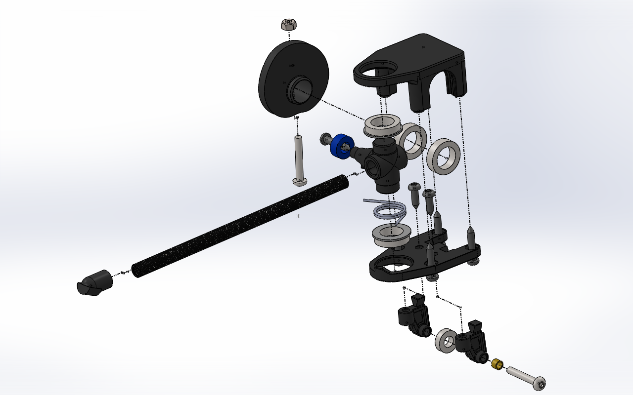
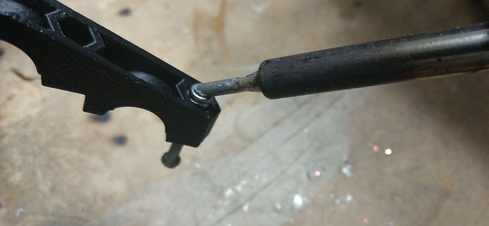
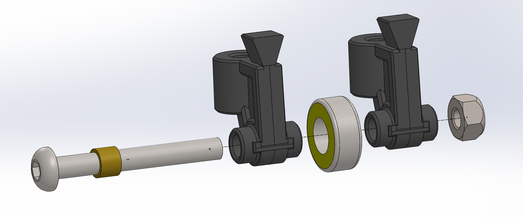
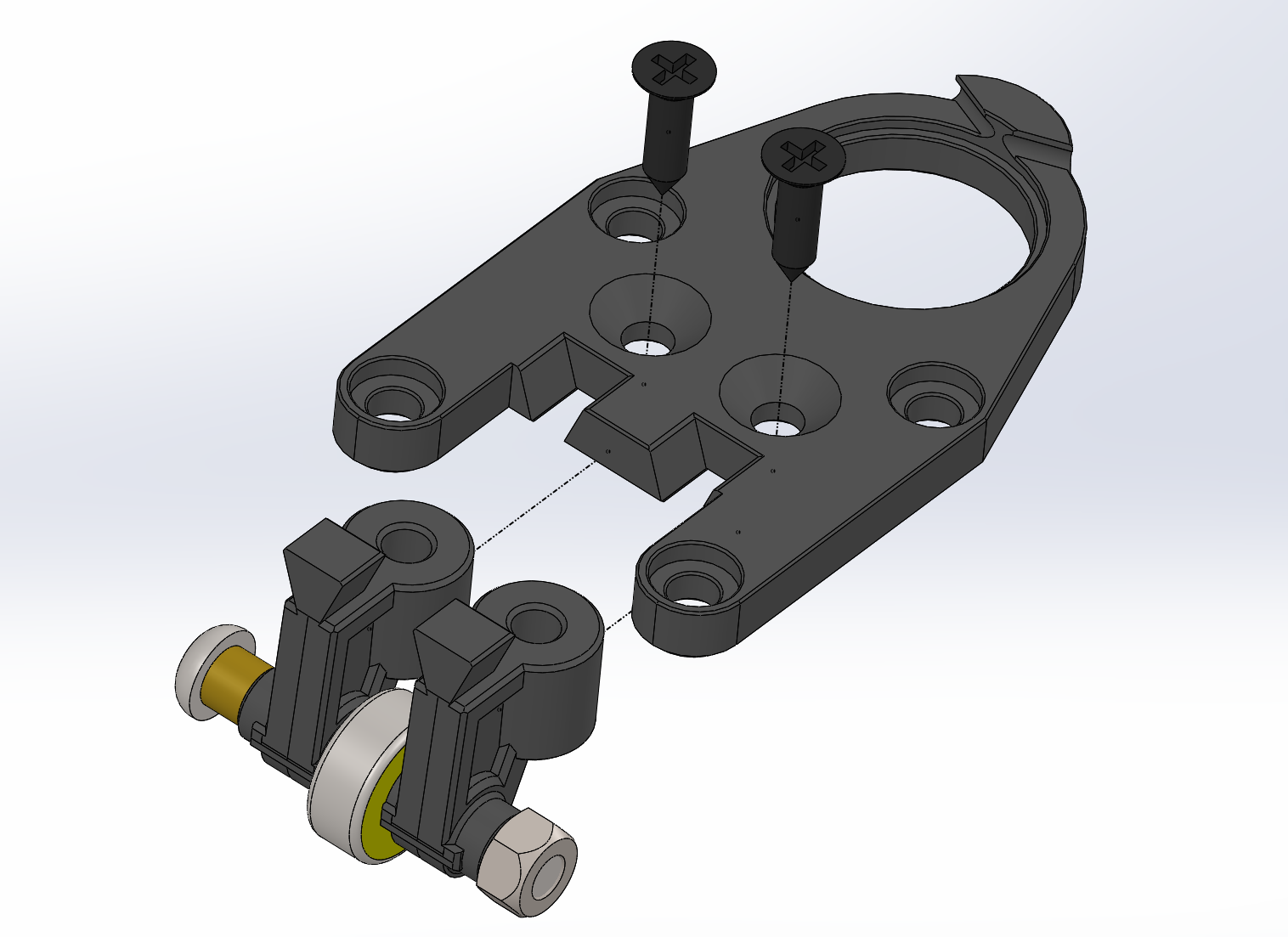
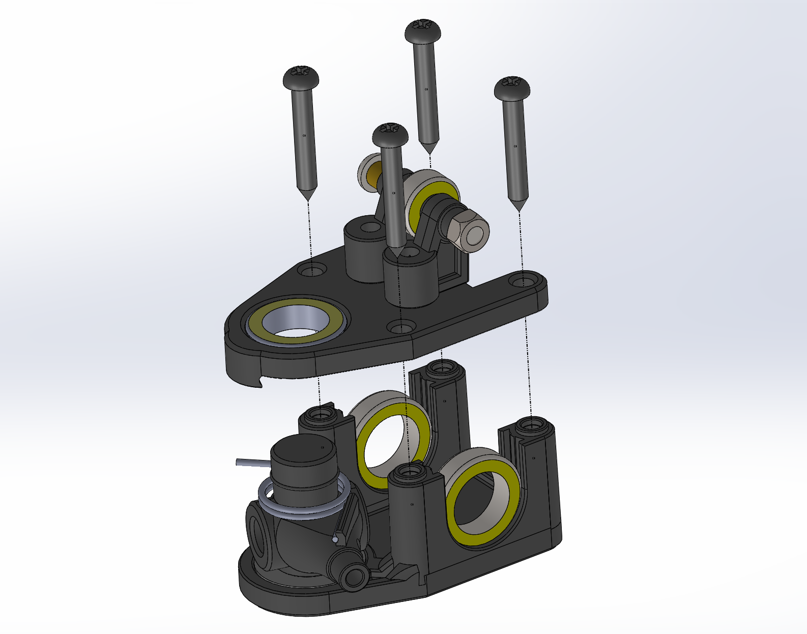
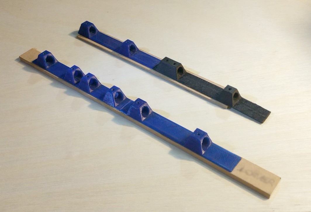
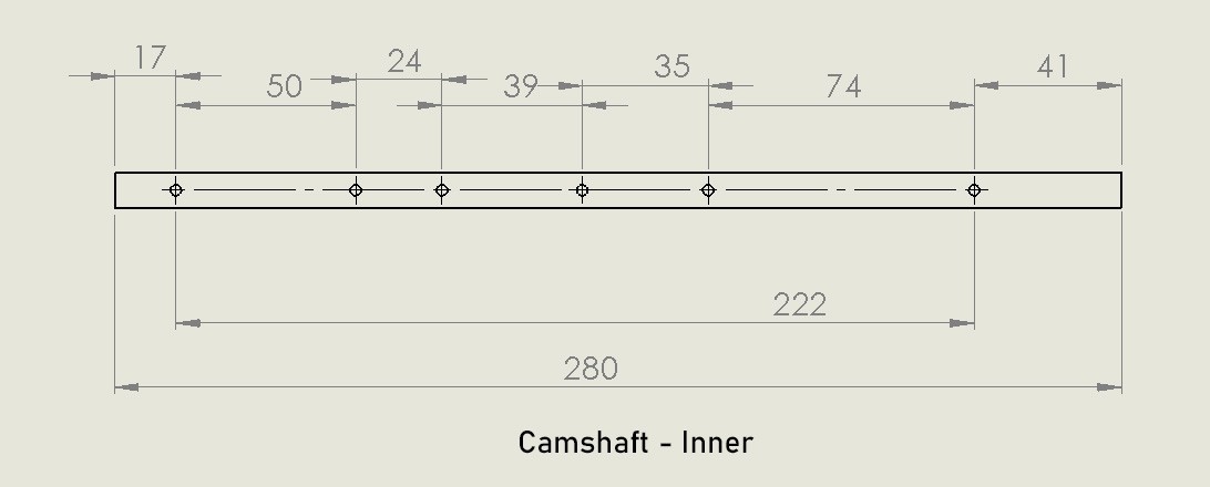
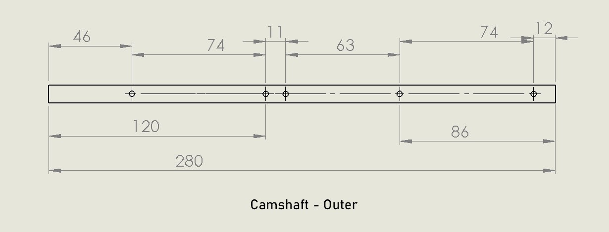
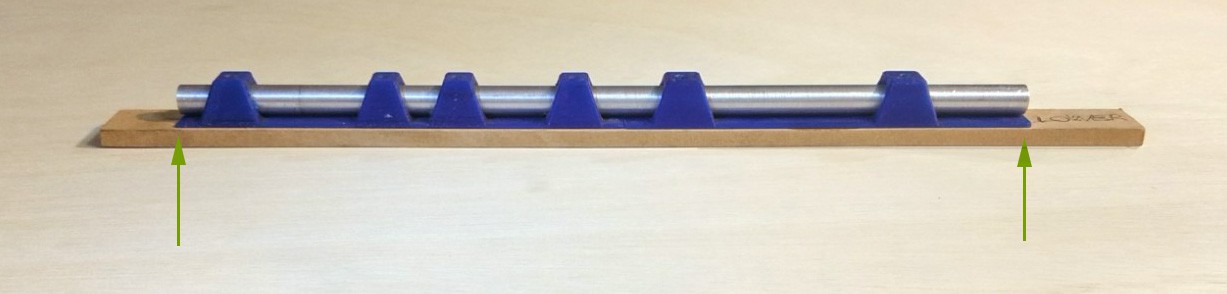
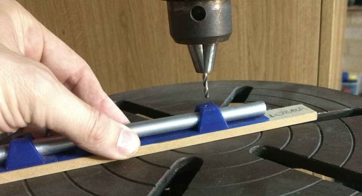
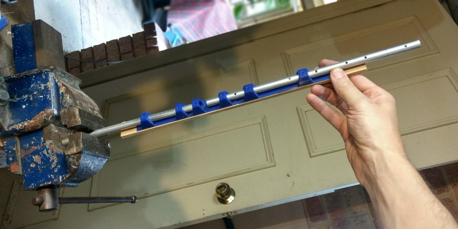
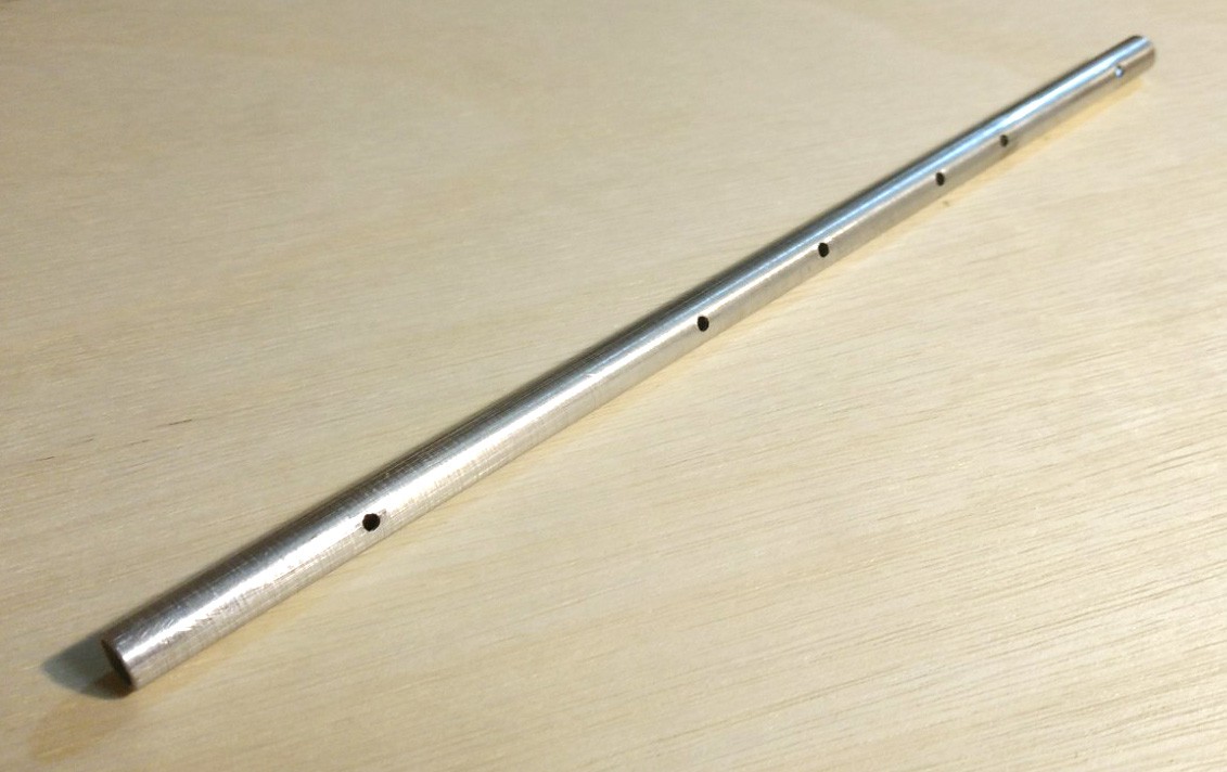
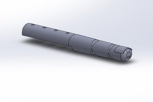
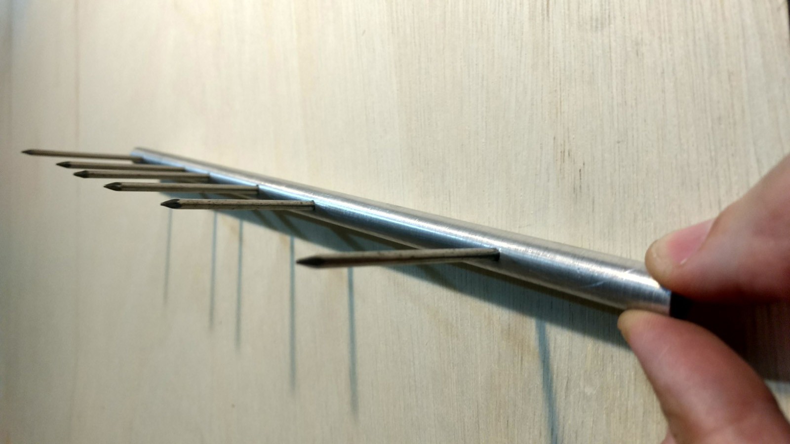
    E) Check the alignment by inserting M3 bolts or nails into the holes and look along the length of the shaft. Ideally all the bolts/nails should all be parallel. If not you should check that your drill bit is nice and sharp and consider drilling a new shaft.
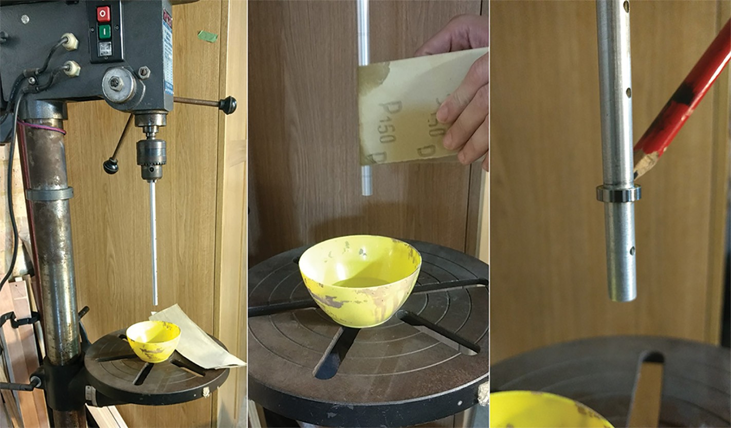
    Shaft Grinding

    Drill press setup: drop the drill press table, clamp the shaft into the chuck using light pressure, put the bowl beneath and fill with a little water.

    A) Using a spare bearing try to push the bearing onto the bottom end of the shaft.
    If the bearing DOES fit on skip to step C).
    If the bearing DOESN'T fit, read on.

    B) Switch on the drill, using a dampened 2"ish strip of sand paper start sanding.

    Start low and work upwards, slowly, methodically repeat for 5-10 sweeps. Always starting low and sanding upwards. Push/pull the paper to use all the sanding surface.

    Stop the drill, wipe down the shaft with a rag. Go to step A.

    C) If the bearing does fit, slide it as far up the shaft as it will go using light wiggling pressure. 

    Draw a pencil mark on the shaft where the bearing is, then remove the bearing.

    This pencil mark is your new start point DO NOT sand below this line.

    Return to step B start from pencil mark. Once the bearing reaches the drill chuck swap shaft ends and repeat step B for the remaining unsanded part of the shaft. 

    You should now have a completed shaft.

    Repeat the whole process three more times making sure to make two inner shafts and two outer shafts.

View all 5 instructions

Enjoy this project?

Share

Discussions

Ossum wrote 03/25/2020 at 07:54 point

This project looks fantastic. It's very seldom that I see something that makes me want to just print and build someone else's work without that obsessive desire to recreate it myself, but the work you've done on the cams etc. is really impressive, and the results speak for themselves!

Bit of a bummer that we're stuck in lockdown for 21 days, time to start pricing the parts at least I guess!

  Are you sure? yes | no

Russell Munro wrote 03/25/2020 at 08:15 point

that's a high compliment! Thanks Ossum. 

  Are you sure? yes | no

Russell Munro wrote 03/15/2020 at 07:20 point

Are you keen the job this project? I would like to use a PS2 controller to drive the spider instead of an RC controller. Using something like an Arduino or similar with Bluetooth and outputting pwm to signal the motors controllers. 

I have the skills to do it but not the time. If you are keen to help develop the above i would love to hear from you.

  Are you sure? yes | no

Russell Munro wrote 03/13/2020 at 00:44 point

@smitty97 so glad you are keen to build! You will need difference Cam profile for 6 legs and you may have balance issues but I will help you out where ever I can. 

  Are you sure? yes | no

smitty97 wrote 03/13/2020 at 00:51 point

Think so?  i was going to make the gait LRL and RLR sort of move together.  Speed might be a little off when doing turns but looks like the legs move fast enough for it not to matter.

  Are you sure? yes | no

Russell Munro wrote 03/14/2020 at 01:52 point

consider that the 8leg unit weighs about 1kg, each leg spring provides about 250g of force. so 4 legs need to be in contact with the ground at one time. with Using 8 leg parts for 6 leg version and using a RLR and LRL config you will have 500g of force on one side and 250g on the other, and you will like see flip-flopping from side to side as it tries to walk.  

  Are you sure? yes | no

smitty97 wrote 03/13/2020 at 03:06 point

Hey would you mind sharing a parasolid export of the assembly?  Would make mods i need to do much easier to make.

  Are you sure? yes | no

Russell Munro wrote 03/13/2020 at 04:39 point

Sorry mate, I'm not too keen to give those out. I can give you drawing files with dimensions so you can create new parts accurately? 

  Are you sure? yes | no

Enrico wrote 03/06/2020 at 10:04 point

So fast! Just call it Valentino ;)

  Are you sure? yes | no

Russell Munro wrote 03/05/2020 at 00:21 point

Wow! followers doubled over night?! Did this project get posted online somewhere that I dont know about?

  Are you sure? yes | no

Daniel Hansen wrote 03/04/2020 at 21:07 point

Simply.. AWESOME!!!

  Are you sure? yes | no

Russell Munro wrote 03/05/2020 at 00:12 point

Thanks Daniel!

  Are you sure? yes | no

Jeff wrote 03/04/2020 at 17:19 point

throw a small hull on the bottom and turn the feet slightly and you would have a high speed water bug :)  Love the project.

  Are you sure? yes | no

Russell Munro wrote 03/05/2020 at 00:13 point

I'll have to try that one day , thanks jeff! 

  Are you sure? yes | no

H wrote 03/04/2020 at 17:02 point

Love its speed and the off-road demonstrations. I also like how you used spring-loaded cams instead of fixed crankshafts which makes it more compliant. Do you think it would still work if you reduced the legs to 6 or 4?

  Are you sure? yes | no

cr0sh wrote 03/04/2020 at 20:49 point

I bet it'd work fine as a hexapod - but might have problems with movement as a quadruped. 

It basically is relying on having a stable number of legs on the ground at any one time, like most non-dynamic walkers. But maybe if it moves the legs fast enough, there'd be a stable "base" of legs on the ground even with only four. 

If it could keep at least three on the ground at any one time, it might just have a chance. 

It's a very interesting and fun-looking project, that's for sure!

EDIT: 

I meant to add that it might be neat to make a "centipede" like this, but with each segment having only two or four legs, with each segment connected to each other using some other kind of ball joint or other "universal" means. 

There would probably have to be a shock-absorber system added, too. Two motors per each segment, and perhaps a single controller, and some kind of network backbone connecting them all (or daisy chain - CAN bus would be perfect). 

Make it as long and creepy as you wanted (at the expense of extra weight and power usage - maybe a battery per segment might be added - that shares power with the entire system?)

  Are you sure? yes | no

H wrote 03/06/2020 at 06:16 point

I've heard non-dynamic quads can lift two legs at a time and not fall over as long as the legs move fast enough. I should get around to trying it on my quad.

  Are you sure? yes | no

Russell Munro wrote 03/04/2020 at 22:57 point

I've been exploring 6 feet, the issue is that the driving cam becomes very lumpy and reverse becomes difficult. I'll explain in a post on the future.

  Are you sure? yes | no

H wrote 03/06/2020 at 06:11 point

Oh yeah I can see how powering one leg then two would make the drivetrain uneven, though I'm surprised reverse is difficult. I'll check your post when you make it.

  Are you sure? yes | no

smitty97 wrote 03/12/2020 at 15:49 point

I'm going to make a 6-legger.  parts ordered!

  Are you sure? yes | no

Russell Munro wrote 02/16/2020 at 13:20 point

Thanks Dejan! 

  Are you sure? yes | no

Dejan Ristic wrote 02/16/2020 at 13:06 point

VERY cool. As an extra bonus it has that uncanny valley creepyness of the Boston Dynamics robots. Will follow this project for sure.

  Are you sure? yes | no

Similar Projects

Does this project spark your interest?

Become a member to follow this project and never miss any updates