 Jeff Cooper
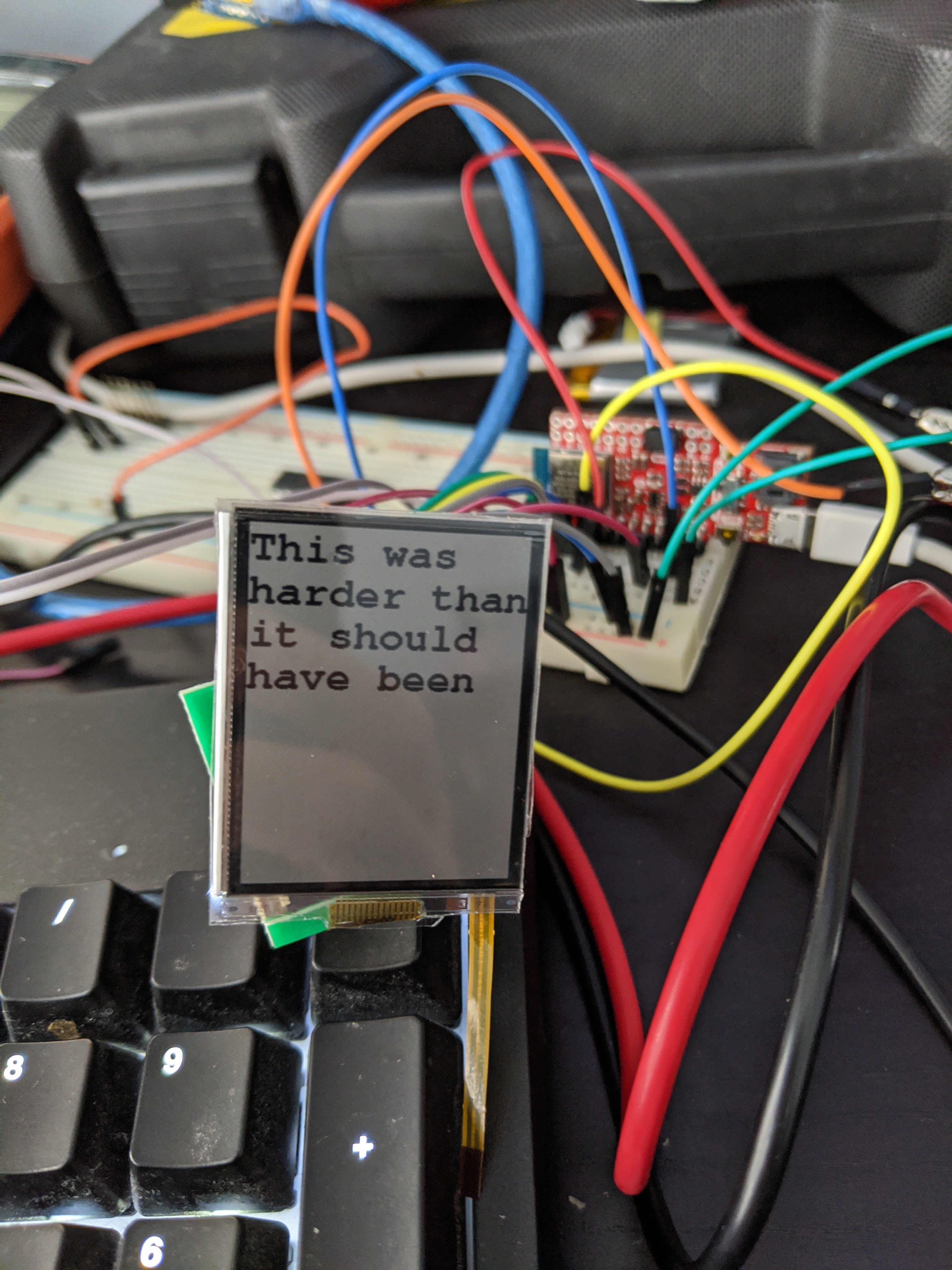
Headline first: the new display arrived on Friday, and it works! It took some wrangling, though.
With no code modifications, I was able to plug in the new display and flash it black and white. However, the "white" looked kind of gray. When I looked closer, I saw that every other line of pixels was actually black. Trying to print some text also had some funny interlacing effects, as if every other line was getting skipped, and the remaining ones were being stretched out.
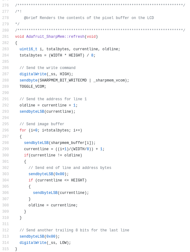
I puzzled over this for an hour or so, then decided to look closer at the datasheet versus the code. Here are the relevant sections (datasheet from Sharp, code from Adafruit). See if you can spot what might cause every other line to be skipped:
Okay, that's not obvious. Does this help?
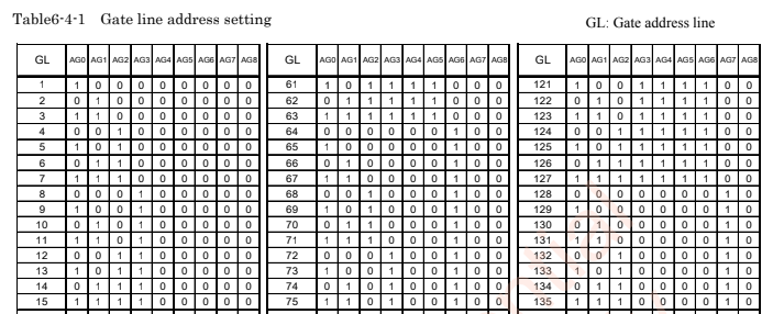
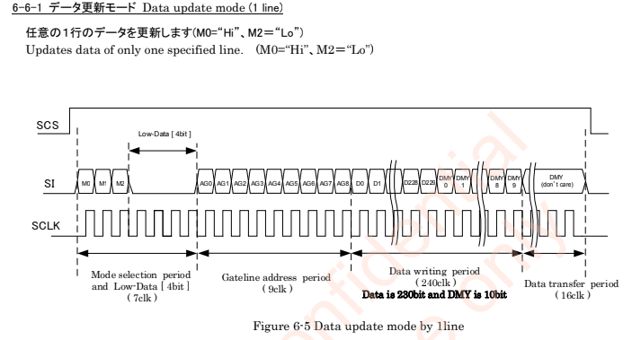
The problem, as it turns out, is that the Adafruit library was sending 8 bits of mode selection (all zeroes, line 303 in the screenshot) followed by 8 bits of line address (306). The "sendByteLSB()" method clocks a byte least-significant-bit first. But wait! The spec says that there are seven clocks of mode select (3 meaningful bits, then 4 bits of "low data") followed by nine bits of line address. This makes sense; there are 303 lines on this display, which is more than would fit in 8 bits of address. Now look at the AG0 column in the address table. The first bit that's sent is the least-significant bit of the line number, represented in binary. If we're sending an extra zero of mode select bit, that gets interpreted as AG0. Then we send the least-significant 8 bits of the line number, which effectively get shifted by one, meaning that we only send data for the even-numbered lines in the table (where AG0 = 0).
Making a local copy of the library and modifying it to send seven and nine bits rather than 8 and 8 solved the problem.
Next up, I wanted to get rid of that big "NO OPTICAL BONDING" sticker so I could actually see what I'm doing. "Optical Bonding" essentially refers to the process by which you can put a protective layer on top of a display without interfering with its optical properties. Adnan from FLEx had sent me this in our correspondence:

I, being the lazy mechanically-challenged hacker that I am, decided to ignore this advice. I had a spare adhesive plastic protector for a cell phone screen laying around, so I cut a piece to size with an xacto knife and stuck it on. After trying this on the broken display first, which digikey said I didn't need to send back, I proceeded to do it on the working one. As you can see in the photo at the top of this post, it doesn't seem to interfere with the optical properties of the display itself. Then I turned on the frontlight. In what should absolutely not have been a surprise, the manufacturer knows what they're talking about, and the light was super blotchy. Unfortunately I can't get a picture of this, since I can't find anywhere that sells a 1mm pitch, 2-position FFC connector. I was only able to power the light by holding jumper wires to the contacts on the ribbon, which required both of my hands. In my opinion, this isn't a huge deal: if I'm using the light on my watch screen, it's probably because I want to see the time in the dark, not because I need to admire the screen or read a large block of text.
At this point, I think I have everything I need to order the first round of PCBs, which I have re-laid-out and re-routed five times at this point.
Discussions
Become a Hackaday.io Member
Create an account to leave a comment. Already have an account? Log In.