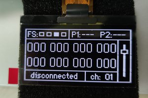
I had a rough idea of what I wanted to do, and a rough idea how to go about it. I wanted to design a meter that would take three differential inputs, calculate the phase relationships between them, and display the result as a phasor diagram. I needed three inputs so that the meter can be used to teach three phase theory as well as reactance and impedance.
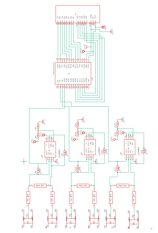
The electronics is fairly simple; a microprocessor to process the input signal; high impedance input circuit to protect the meter; de-amplification to reduce the input voltage down to the ADC range; and a display to output the results to.
I chose an ESP32 as the microprocessor because it’s fast and has a good amount of memory. The DEV Kit is relatively cheap at £7.00 so I decided that it made sense to use the dev kit as a component, and not design the chip and its communication and timing circuits separately into the PCB. I chose to protect the inputs with 22MΩ 10,000V axial resistors. I used LM358 op-amps for the amplification circuit, and also as a buffer to a potential divider to provide a dc offset to the input signal so that it can be read by the ESP32’s ADC. Below is the schematic of the instrument before the voltage regulator and de-coupling capacitors are added.
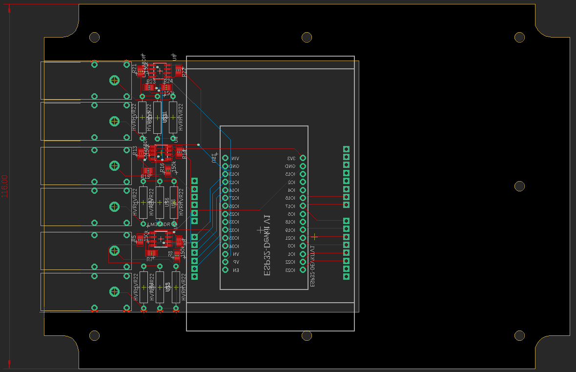
I used Eagle Free Edition to produce the PCB, however this software has a limited PCB area. You can import a bigger PCB footprint, but you can only place components in a limited area. I drew the PCB outline to fit the enclosure I had chosen, and imported it into Eagle as a DXF file (import has to be in the Dimension Layer). As you can see in the board layout below all the components are placed in the small area available in this edition of Eagle.
I will post a commentary on the software development in a later post. Meanwhile here is a video of the Phasor Display in action
 Marius Taciuc
 tomcircuit
 Ghani Lawal