 CD Xbow
I had an old i5 Dell laptop die after it was challenged by a cup of coffee. I knew things were bad when it went "FFFFFT", a feint smell of smoke was evident and darkness took over the machine. After fiddling with it for a bit and getting nowhere, I decided it had gone to silicon heaven. I pulled it apart and removed the hard drive, DVD drive and a few other bits and pieces.
I recycled the hard drive into an old i5 Toshiba laptop with a stuffed drive. The gods must have been smiling on me because the machine booted perfectly and I only needed to do a little argy bargy with drivers before it all worked perfectly. Feeling to be on a bit of a roll I thought I might try and reuse the LCD display with a Pi using one of those driver boards you can buy online. The one for my Dell was this one:
HDMI+DVI+VGA LCD Lvds Controller Driver Board Kit for Panel LTN140AT16 1366X768
A modest $23 USD from Amazon. You need to get one to match the display, this includes electrical and cable compatibility. Your panel number eg LTN140AT16 is essential for choosing a compatible board. You can find it on the back of your display or look it up online if you have a name brand machine that you can find detailed specs.
Blow me down if this didn't work first time when I hooked a pi 4 up to it.
Feeling flushed from success, I decided I would reuse the chassis of the Dell with the LCD and mount the Pi4 inside the case along with the driver board and a PSU.
The main body was a nicely made magnesium one but needed significant adjustment with an angle grinder to get the parts to fit. Magnesium makes very satisfying sparks when it contacts with a grinder. WARNING - Make sure you file off any rough edges, they are very hard and sharp
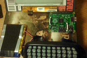
The first picture shows the stripped chassis and most of the magnesium cross pieces removed. I was worried it might start to flex, however the remaining magnesium shell is still stiff and rigid.
Next I laid out the parts in the case (Pi4, driver board, keyboard) and hooked up the LCD to the driver board. Pi4 booted, displayed properly and the Bluetooth keyboard/trackpad connected OK. So all working well. Next the fiddly bits.
The second picture shows the layout of the major components. The driver board had to go to the left back so the ribbon cable could reach the display. Note the some of the other inputs are still accessible so you could have video in functionality, to the screen at least.
The Pi4 occupies the right back with view cables hanging out of it. In this position the USB and network connection face out the back of the case on a very convenient way. Not so convenient to change the SD card, but life is full of compromises.
The keyboard/Trackpad sits at the front.
There remains space to the left of the keyboard or between the keyboard for a power supply
To be continued.
2. The fiddly bits - putting it all together
3. Power Supply
4. Finishing it off
5. In use
5. Further mods.
 j0z0r pwn4tr0n
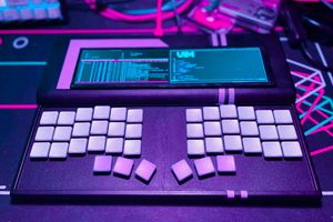
 0x17
0x17
 Bradley Austin Davis
 pcadic