 Michael Gardi
Motivation
So why would I want to undertake an H-500 Computer Lab reproduction? Because most of the projects that I have been working on lately follow the same pattern:
- They are reproductions of cool computer toys and devices from the 60's.
- Have tremendous educational value (when first released and even now IMHO). To that end they usually shipped with well written and instructive manuals.
- Feature unique and noteworthy designs.
- Due to their age they have become rare and thus expensive and hard to get.
- Perhaps most importantly I think that the devices themselves and their designers deserve to be remembered and honored.
- As a bonus for this particular project, I'm Canadian and the H-500s were manufactured in Canada.
So the H-500 is a very good fit for my interests and skill set. Plus I really want one ;-)
Design Goals
With this reproduction I hope to provide the best H-500 Computer Lab experience possible. What do I mean by that? Well...
- Visually my reproduction will be clearly recognizable as an H-500. I will strive to provide an outwardly accurate appearance of the original to the best of my ability and within the constraints of the implementing technologies. Bear in mind that I can't afford one of these so I will be working from images and the kindness of actual owners to provide me with details.
- Operationally my H-500 will perform like the original. A user will be able to work through the experiments in the Lab Workbook without change or issues.
- I would like for this project to be easy to well, reproduce. To this end I will only be using 3D printed parts and readily available components and materials.
- I will try to keep the total project cost to a minimum.
- A complete set of instructions, parts list, and STL files will be posted to Instructables at the completion of this project so that others could make one should they choose to.
So hopefully my H-500 reproduction will look and work like an original, but I can guarantee (at least for version 1) that the very cool PCB with "surface mounted" components used in the original will not be part of the final design in order to meet cost and reproducibility goals.
(Maybe version 2?)
Rocker Man
Well rocker switches is actually the reason that I started considering this project. At the end of my Mostly 3D Printed Rocker Switch project I posted the following:
With a workable and customizable rocker switch in my tool kit now, I'm looking at you PDP-8/I ;-)
 The remark was made somewhat tongue in cheek, but it did get me thinking about it since I love the look of the switches that they used. I actually started researching the possibility of making an 8/I replica. I soon discovered however that Oscarv had already created an awesome 2:3 replica the PiDP-8/I which I purchased (I'm just waiting to finish this project before assembling it). So not much incentive to duplicate his great work.
A short while later I was looking at the System Source Computer Museum Toy Computers page and I saw the DEC Computer Lab. WOW. This was actually a much better fit for both my interests and skill set. I have made replicas of six of the other computer toys on this page five of which I created myself. And the DEC Computer Lab uses the same rocker switches as the PDP 8/I. Perfect.
Making the Switches
My starting point was an STL version of the PDP 8/I rocker switch that I found at Vince Slyngstad's PDP-8 Stuff page.
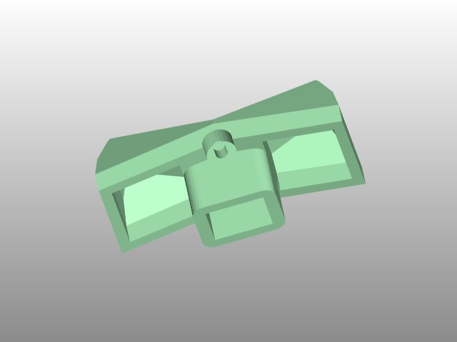
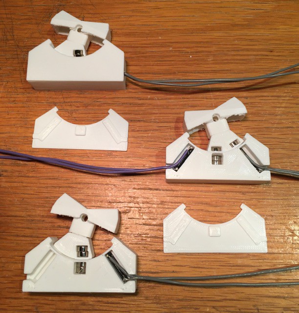
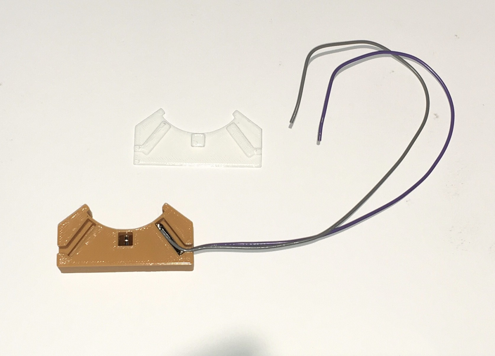
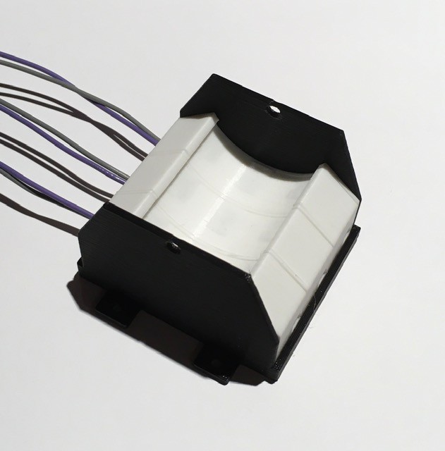
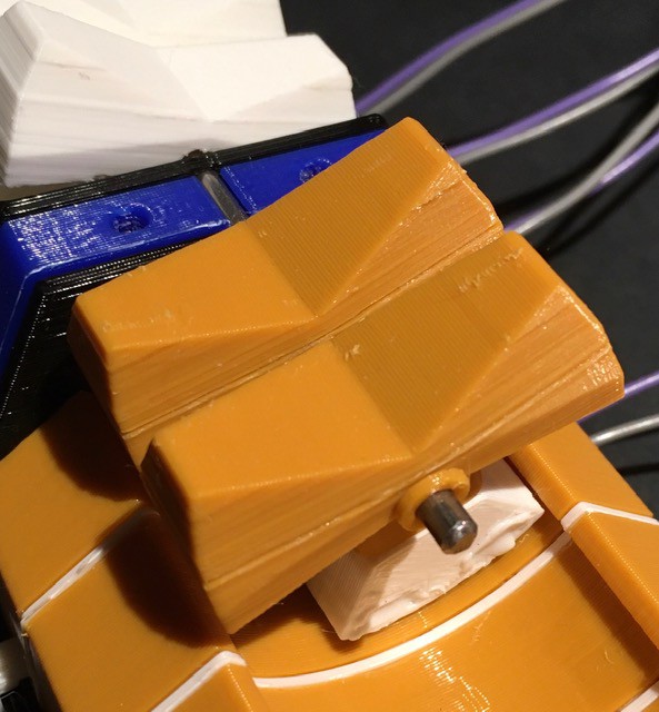
I modified it slightly to have a hole at the pivot point instead of a shaft. Then I modeled a "counter weight" to hold the switch magnets and a corresponding base for the "reciprocating" magnets and the reed switches. You will notice that there are two kinds of counter weights. That's because there are two kinds of rocker switches required, a momentary "spring" return for the three H-500 pulse switches, and an ON-ON variant for the eight input switches.
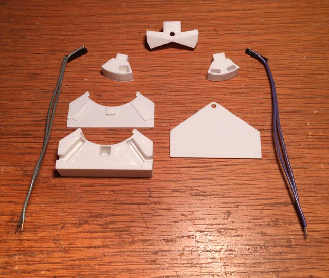
The base has slots and wire guides for each of two magnetic reed switches ( Digi-Key part number 2010-1087-ND). The wires are soldered to the tips of the through hole pins.

Assembly of each switch is pretty straight forward. Insert the reed switches and magnets (making sure that the magnets in the rocker and the base are oriented to attract) then snap on the base end plate. Note that the momentary contact switches only need one magnetic reed switch.
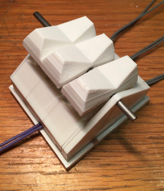
I printed a base and added end pieces to accept a 1/8 inch steel rod to hold the individual switches together for testing.
Finally here is a video of my switches in action. The end switches are "spring" return and the middle is ON-ON.
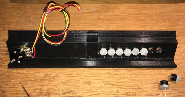
Switch Panel
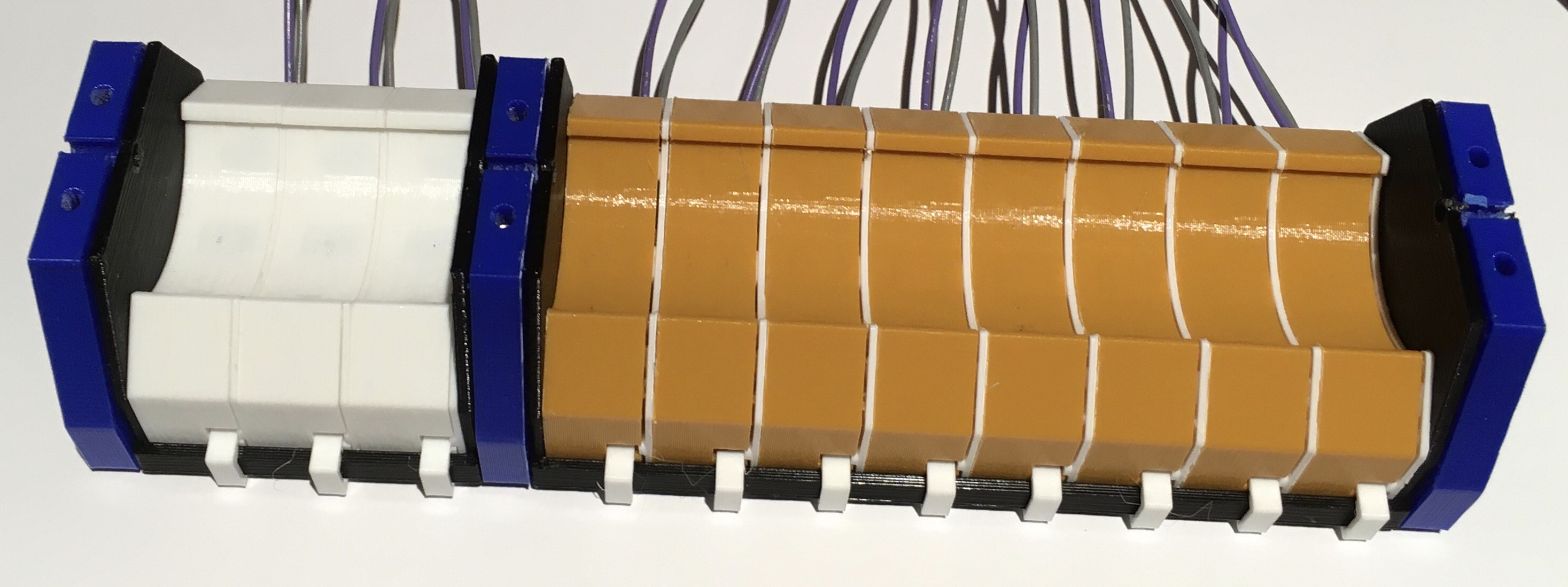
With the switch design complete I forged ahead and built the bottom part of the H-500.
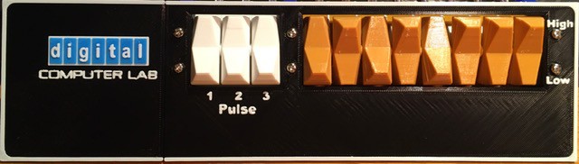
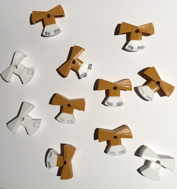
I started by preparing the eleven rocker switches required, three momentary "spring" return types for the H-500 pulse switches, and eight ON-ON variants for the input switches.
I found some "light brown" AMZ3D filament that I though might be a good fit for the 8 input switches. Before printing some test switches I split the STL file into two parts to avoid having to use supports.
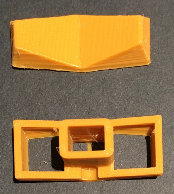
I'd rather spend a few seconds gluing, than 10 minutes removing support material. You end up with a small seam (where it will never been seen) but with a much cleaner print.
The above pictures appear way too yellow and do not do justice to the actual color which has a nice caramel/butterscotch look to it. The picture below is a better indication. It's certainly in the ballpark based on pictures of H-500s that I have seen online.
I took care and made sure that the magnets were all oriented the same way and used my 3D pen to secure them in place.
Next I prepared the eleven rocker switch bases. They are all the same as the one below. You will notice that there is only a single reed switch. I had already decided that I would use an Arduino to manage the clock and pulse signals (reading the clock rate, generating the clock signals, debouncing the pulse switches, etc., more on this later in the project) so I thought I would take advantage and generate the input switch signals based on a single reed per switch knocking about $20 off the BOM. Also I'm not sure what the final assembled layout will be so I attached extra long leads.
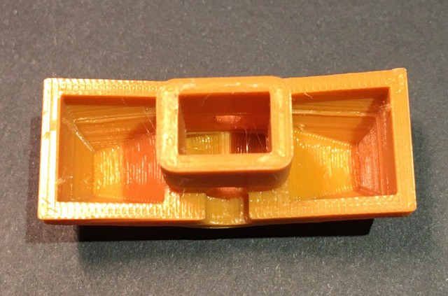
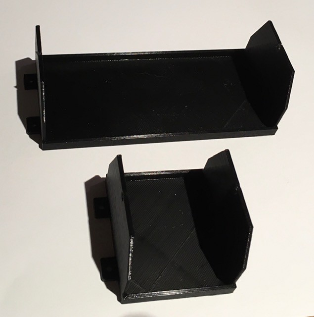
I designed two "cradles" to hold the switch bases.
The bases slide in snugly.
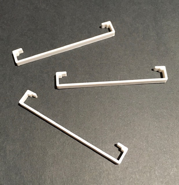
I made some simple clips to hold the base pieces securely in place.
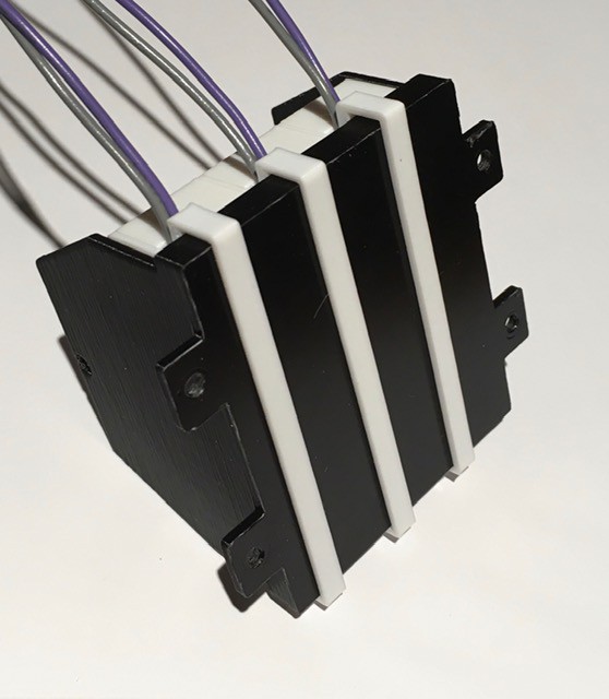
Same for the eight switch cradle. I'm running a bit low on filament so mixing colors a bit.

Next I printed some mounting plates. They have slots for M3 nuts to ensure a strong bond.

Connected the cradles to the mounting plates with M3 x 10 bolts.
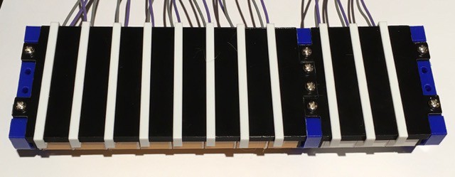
Cut a 1/8 inch steel rod to span the length of the combined switch assembly and printed some small spacers to help align the switches. (NOTE: In the final version of the assembly I switched the wires on the 8 toggle switches to the other side to make installation a little cleaner.)
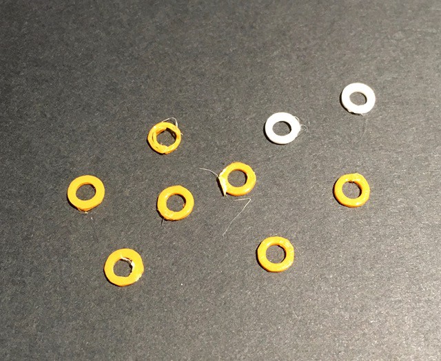
Starting from one end I began slowly sliding the rod through the pivot holes attaching the rocker switches with their counter weights as I went. Between switches I inserted one of the gaskets.
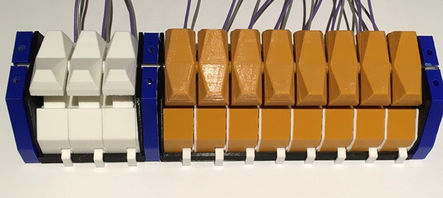
When done the switch assembly should look like this.
I printed the face plate for the panel (in two pieces, need a larger volume printer). I paused and changed the filament color multiple times to print the text and the logo. All that's left is to attach the switch assembly to the face plate. (Or is it the other way around, the switch assembly is quite massive.)
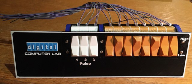
That's it. The switch panel is done. It is tweaked a bit from the original. I had to make the characters bigger by about 20% to get them "print" correctly when extruded. The switches when assembled ended up being a little wider than the originals. Since I had already printed the switches, I made the panel holes a little larger to accommodate them. When I get the chance I'll get some black steel bolts so the heads are less noticeable. All-in-all though I'm extremely happy with the result.
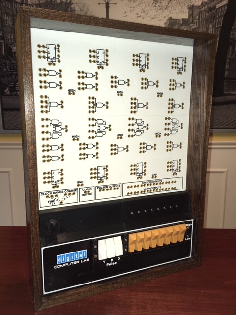
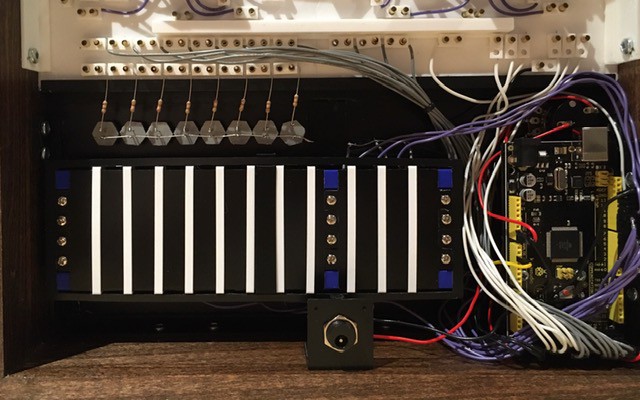
Light Panel
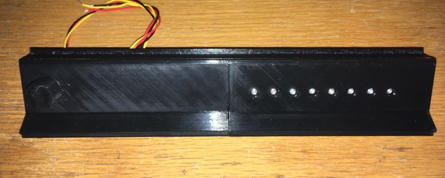
This piece separates the Switch Panel from the Plug Panel, holds the eight output lamps and the fine tuning knob for the clock speed, and also transitions from the higher switch level to the lower plug level within the wooden frame.
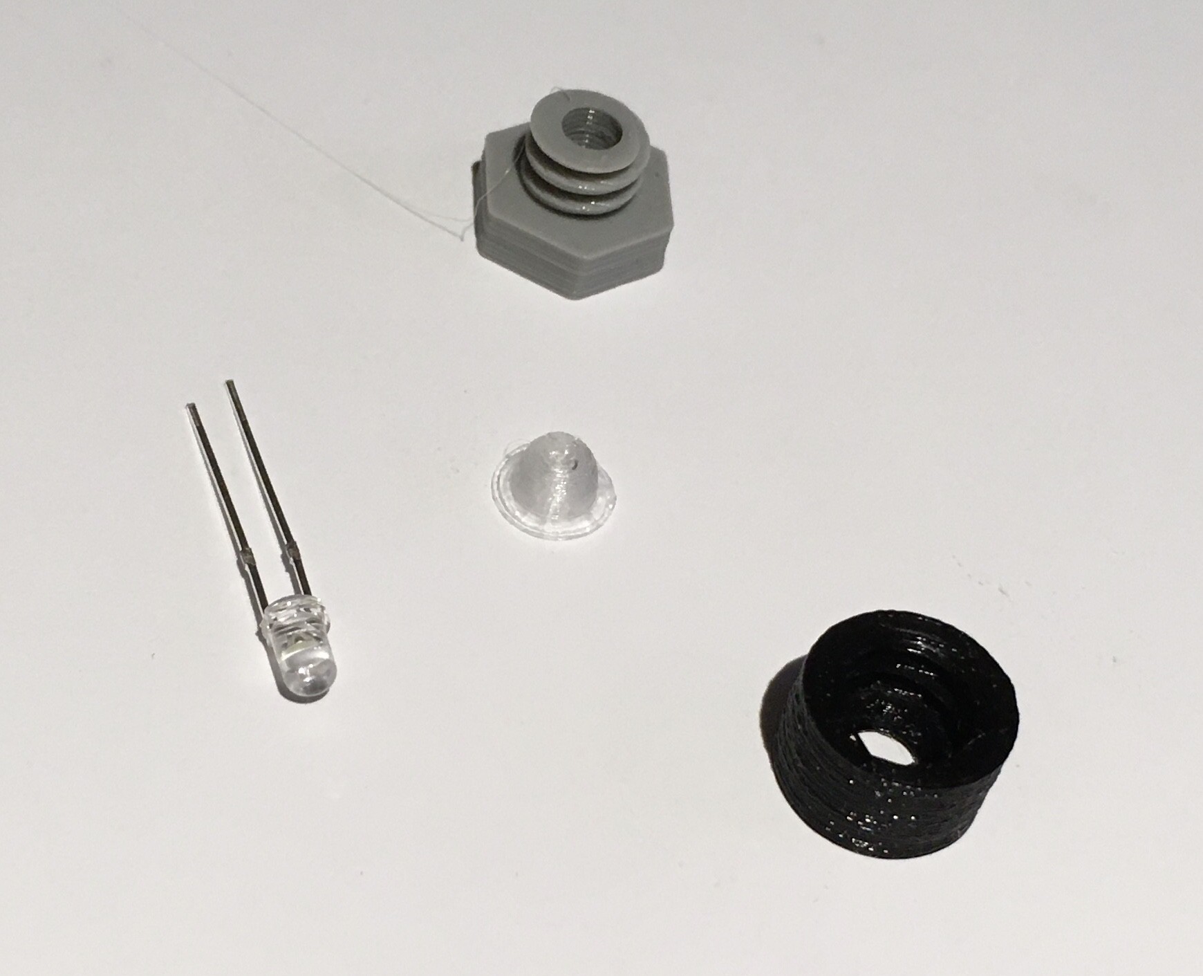
It's impossible to know from just pictures what kind of bulbs they used in the original, but if I had to guess based on the estimated size (about 4 mm) I would say grain of wheat bulbs. I could have ordered some but given the current lead times for delivery of non-essential items I decided to go with what I had on hand, LEDs. I modified my Panel Mounted LED Socket by adding a 4 mm diffuser printed with transparent filament.
When put together it looks like this.
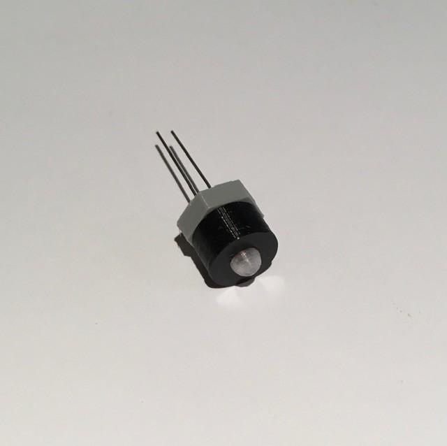
These bulb assemblies were slotted into holes on the back of the Light Panel. The panel itself was printed in two pieces and glued together with the aid of a reinforcing strip. You can see the clock fine adjustment potentiometer mounted on the back as well. (TWTADE/2Pcs wh138 10K Ohm Single Linear Taper Dimmer Potentiometer with On/Off Switch - Amazon)
From the front here is the fine tuning knob that I modeled...
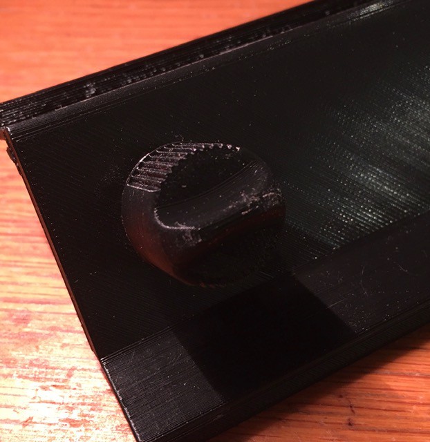
... based on the original.

The "bulbs" ended up looking pretty good. I found that I will have to add a 4K limiting resister to each LED to get the brightness down to incandescent levels.

The light panel is ready to go.
Tic-Toc, Click-Clack, and Blinking Too
All of the active controls for the H-500 are located in the lower part of the device.

These included (taken directly from the Computer Lab Workbook):
- Rocker Switches - Rocker switches can be used to provide either a HI or a LO logic level. If the upper side of the rocker switch is depressed, the two corresponding switch output terminals (directly in front of the switch) are taken to a HI level. If the lower side of the switch is depressed, the two corresponding output terminals are taken to a LO level.
- Pulser Switches - The outputs of the pulser switches are normally LO. When a pulser is depressed, the corresponding two terminal terminals go to a HI level. When the pulser is released its output terminals return to the LO condition. Internal circuits connected to the pulsers make sure that when a pulser is depressed or released, electrical noise generated in the switch is not transmitted to the pulser output. This special circuitry makes the pulsers useful in applications requiring noise-free transitions from one level to another. Rocker switches do not have this feature.
- Clock - The clock provides a continuous train of HI pulses. Clock pulses are 50 nanoseconds wide. The frequency of clock pulses can be continuously varied from less than one pulse per second to over 10 million pulses per second. The slowest range of the clock is obtained by connecting the common clock coarse terminal to the left-most speed-selecting terminal. The repetition rate of the clock increases with each terminal to the right. The fastest repetition rate is obtained by leaving the clock range selector disconnected. Repetition rates within each coarse range can be varied using the clock fine control. (Fully counterclockwise gives the slowest repetition rate; fully clockwise provides the fastest rate.) The clock range coarse terminals are to be used only for selection of clock repetition rate. The clock output is obtained from the two terminals labeled CLOCK OUTPUT.
- Lamp Indicators - The operation of experiments constructed on the COMPUTER LAB patchpanel is monitored by the lamp indicators. A lamp will be ON if its corresponding input is at a HI logic level. A lamp will be OFF if its corresponding input is at a LO logic level. If no connection is provided to a lamp, the lamp will be OFF. Lamps will respond to sustained logic levels and pulses of sufficient duration to activate the lamp filament.
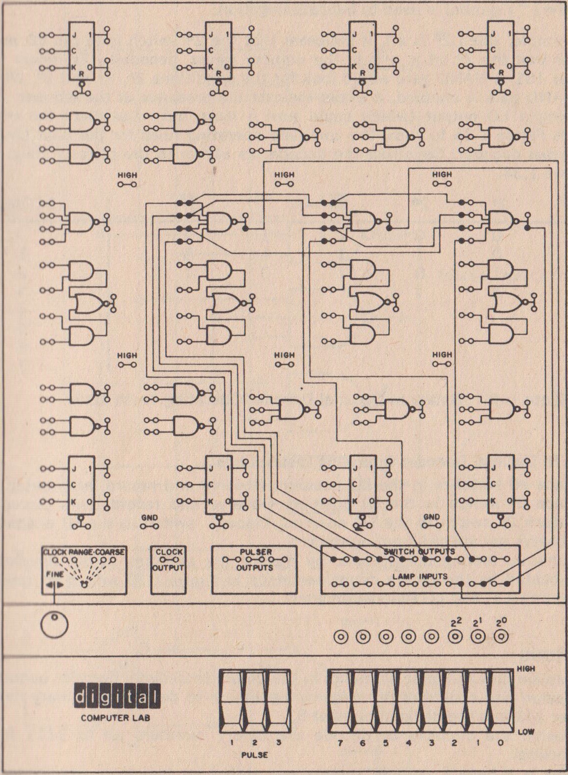
So how were these functions implemented back in the late 60's. Like this:
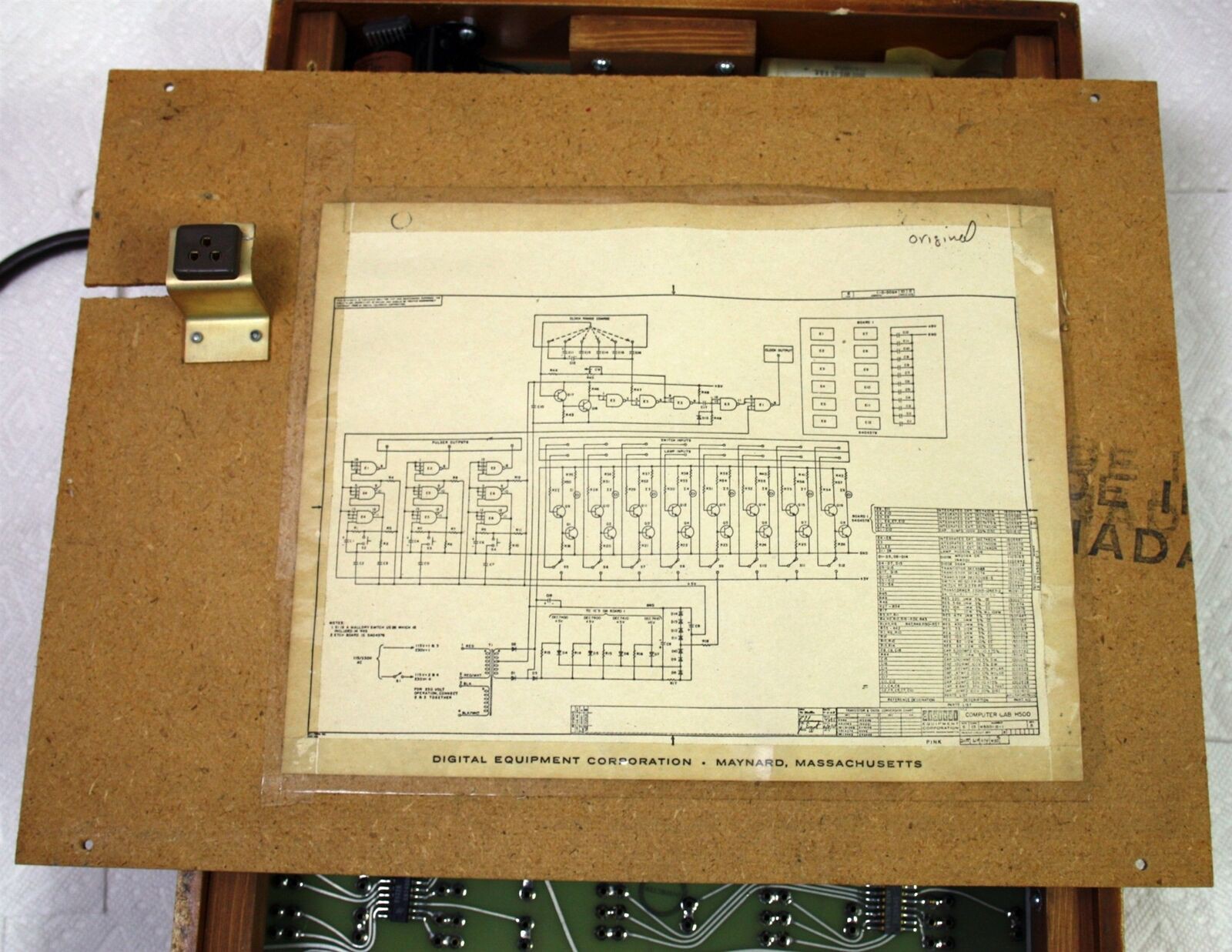
I apologize for the image quality. I'm trying to find a better photo. Looks like this schematic was taped to the back of the frame's rear cover.
Now I'm not going to pretend that I completely understand all of what is going on in this schematic. Electronics is not my strong suit, I'm more of a digital guy. (if anyone wants to help me out here with a short description of what the above circuit does I would be happy to include it in the write-up.) Suffice it to say that the complexity of implementing this circuit goes counter to two of my primary design goals with this project: make it easy to reproduce and not too expensive.
Fortunately I do know what the circuit is supposed to do. So what would be an easy and cheap replacement, understood by today's community of makers, well an Arduino of course. This is what I came up with:
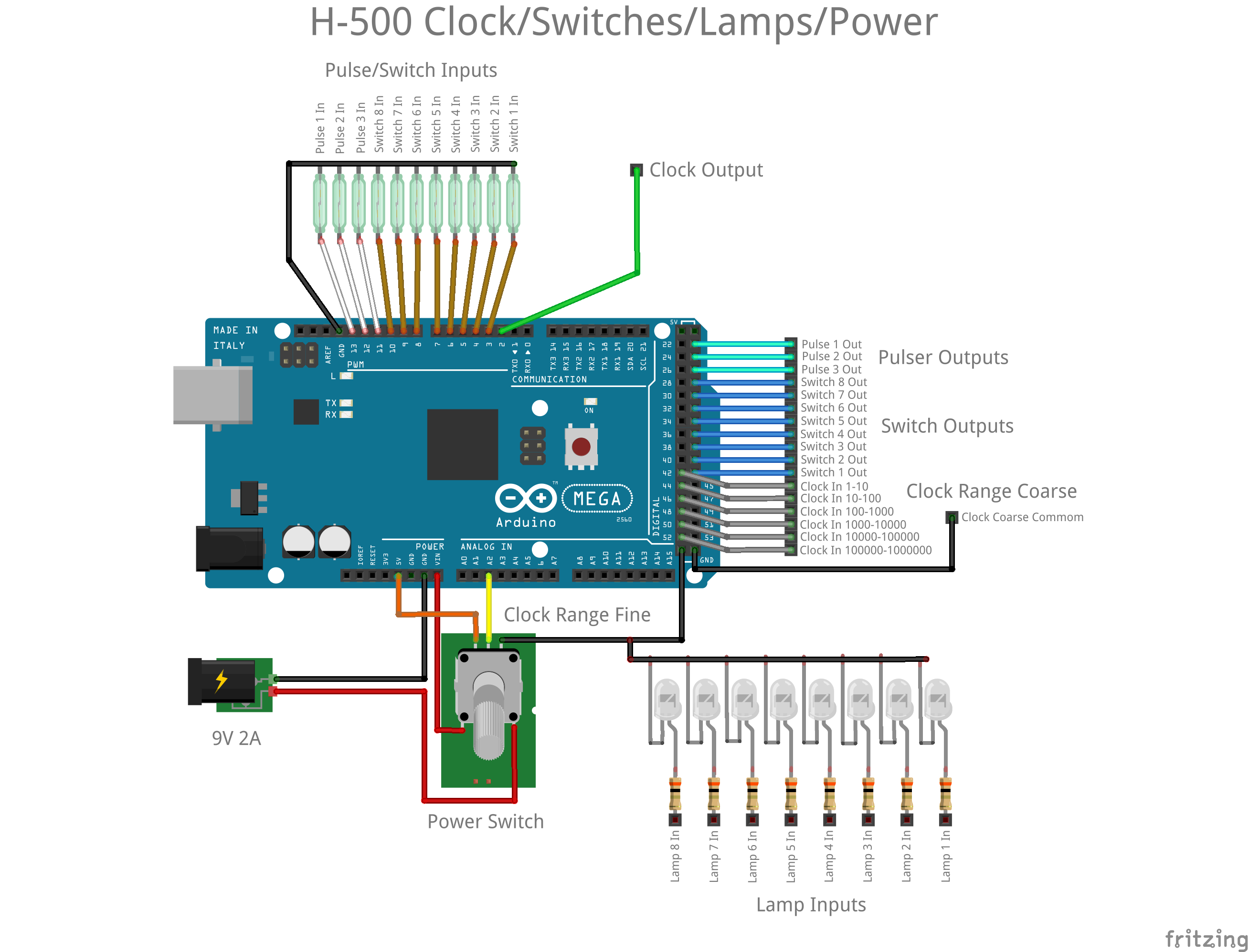
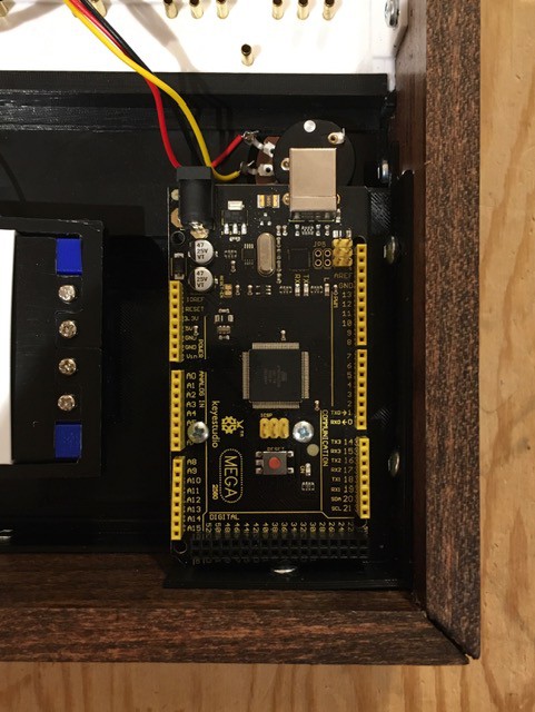
Rocker and Pulser Switches - The magnetic reeds of the rocker and pulse switches are monitored by eleven inputs that are set with their pull-ups enabled. When the normally open reed switch is "activated" by a magnet its input line will be pulled down. The Arduino sketch monitors changes to the reed switches and will only change the state of it's corresponding output line once the switch has been suitably debounced (three consecutive reads 20 milliseconds apart with the same state). In this implementation all switches are debounced, not just the pulsers. We are already at 22 I/O lines so it's a good thing that the Arduino I had lying around was a MEGA 2560.
Clock - Six more inputs with pull-ups enabled were dedicated to monitoring the clock range coarse jumpers. The clock frequency ranges that each enables can be seen on the diagram above. Ranges are checked from lowest to highest, stopping at the first one found to be enabled with a jumper. Also the potentiometer is read via an analog in line and converted to ten steps (1-10) and applied as a multiplier to the lowest value in the selected range. So if the clock range set is 10-100, as the potentiometer is turned clockwise, the clock frequencies will be changed to 10, 20, 30, ..., 100 clocks per second. If no coarse range jumper is set, I leave the clock frequency fixed at one clock per second. Clock pulses are emitted via a digital output line.
Lamp Indicators - Included in this diagram for completeness, the lamp inputs are not processed by the Arduino in any way. Just apply a Hi signal and they will turn on.
Power - A switched potentiometer is used to turn the device on and off as with the original.
Using an Arduino is not without some compromises. First of all I'm using the excellent TimerOne library to implement interrupt driven clock pulses. It tops out at about 1,000,000 interrupts per second, so that's my maximum frequency as well, 1,000,000 clocks per second. On a similar note the clock pulse itself is generated using the digitalWriteFast library. Within the clock interrupt the code is simply:
digitalWriteFast(2, HIGH);
digitakWriteFast(2, LOW);
According to the documentation the digitalWriteFast() "call" takes about 125 nanoseconds to execute. So that means that the clock duration will be somewhere between 125 and 250 nanoseconds. (I'll know more precisely when I can get back into my maker space (kwartzlab) and access a scope.) A little more than the 50 nanosecond duration the original could produce, but I think it will be adequate for my purposes.
I know that I will probably get some feedback for using a "microprocessor" in this project. If were trying for a more authentic replica I would totally agree. However in this case, where I and am shooting for more of an H-500 Computer Lab working reproduction, the Arduino allows me to simply replace a bunch of discrete components with a cheaper, faster (at least for me), easier, better understood solution.
I've added my Arduino sketch to the Files section of this project. It's not pretty but gets the job done.
Plug Panel(s)
After a day and a bit of Fusion 360 modelling and twenty-six plus hours of printing, the Plug Panel "panels" are done.
Printed in multiple parts to accommodate my print bed, and the text is slightly larger than original to work at 3D printer resolutions, but a pretty good result I think. My big "discovery" for these panels was the "Hilbert Curve" option for the top layer.

I was unaware of this PrusaSlicer feature until now, and would certainly have used it in some of my other projects had I known about it (Minivac 601 and Digi-Comp II for sure). It produces a beautiful even matte finish unlike the somewhat "streaky" result I see with the default Rectilinear option. The downside is that Hilbert is quite a bit slower. It added an extra forty minutes or so to each of the four panels I printed. Totally worth it in my books.
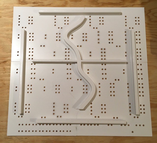
I glued the four panel pieces together. Since the Plug Panel itself needs to be pretty rigid to support the insertion and removal of the patch cables, I designed and printed some support beams and glued them to the underside.
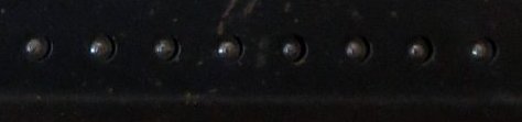
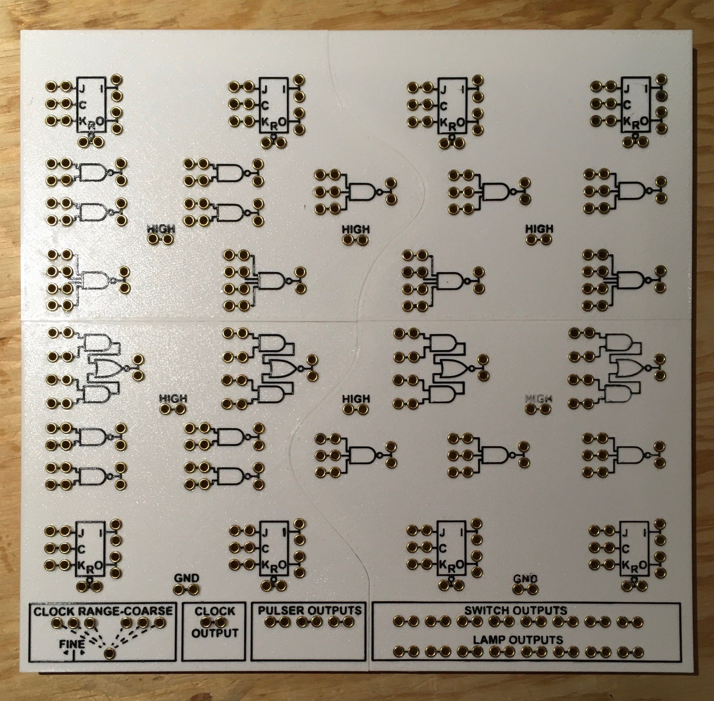
Then it's just a simple matter of installing some rivets onto this panel. By my count, there are 335 "terminals" that patch cords can be plugged into. These rivets are Rolled Flange Head Eyelets sourced from a local supplier (Spaenaur E-412).
I had done a number of test to try to get the perfect hole size so that the rivets could be just pushed in with a nice friction fit. Unfortunately halfway through printing the panels I made a small adjustment to my first layer height. So in the end the two right panels worked as expected, but the ones on the left required a small dab of glue applied to the side of each rivet.
Plug Panel Wiring
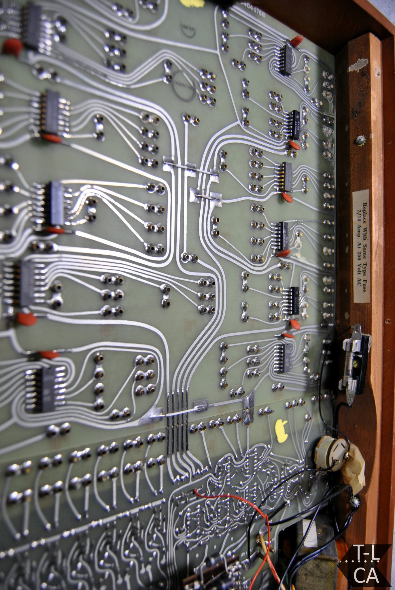
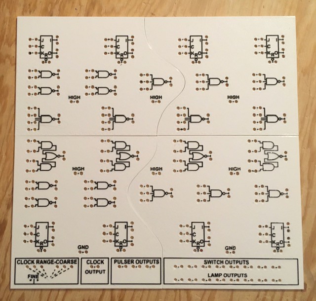
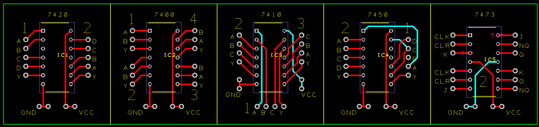
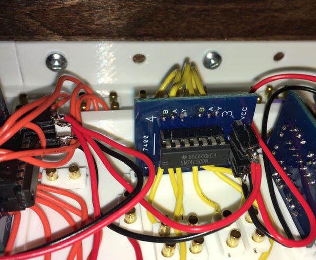
The circuits represented by logic symbols on the top of the board are implemented with a dozen 7400 series ICs underneath.

By looking at the logic symbols and using pictures of the wiring for the original H-500 I was able to determine the chips used:
- SN7400 - 2 Quadruple 2-Input Positive-NAND Gates
- SN7410 - 2 Triple 3-Input Positive-NAND Gates
- SN7420 - 2 Dual 4-Input Positive-NAND Gates
- SN7450 - 2 Dual AND-OR-Invert Gates
- SN7473 - 4 Dual J-K Flip-Flops with Clear
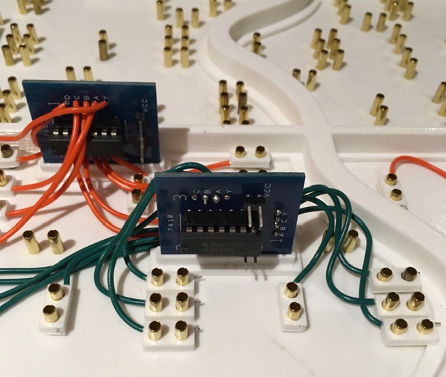
Part way through this is what it looked like:
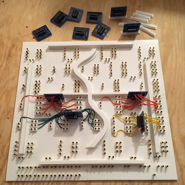
There's a few things to note here. First of all I decided to make my life a little easier by creating some breakout boards for the 74XX chips. My initial though was to just "dead-bug" the chips and solder the leads directly to the pins. It would have worked but the appeal of re-arranging the pin-outs to be more consistent with the layout of the panel, plus having a label on each pin won out. Here's the PCB:
I created a small base for the PCBs so that I could stand them upright since there was no room to lay them out.
My plan was to solder the wires coming from the break-out boards directly to the brass rivets. It turned out that this was a lot harder than I thought it would be. I really should have tested this much earlier in the process. I don't know if the brass was coated with something but the soldering iron had to be applied to the rivets way too long to get a good join. As a result the panel holes melted and got too large to hold the rivet securely in place. I needed a plan B.
They say the necessity is the mother of invention, and I think the solution I came up with is actually better than if the soldering had worked. I made some mechanical "fittings" to securely attach the wires to the rivets:
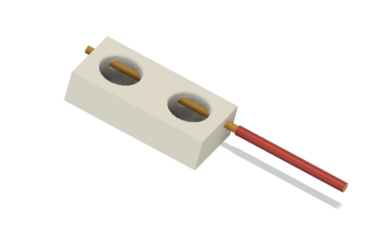
Just insert the wire into the horizontal hole and slide the fitting over a pair of rivets representing a circuit lead. These work great, are quick and easy to install, and actually reinforce the rivet's attachment to the panel. An additional benefit is that a whole PCB "circuit" can be removed from the panel should the need arise to troubleshoot. Here's a closer look.
So with the bugs ironed out, I finished the Plug Panel wiring.
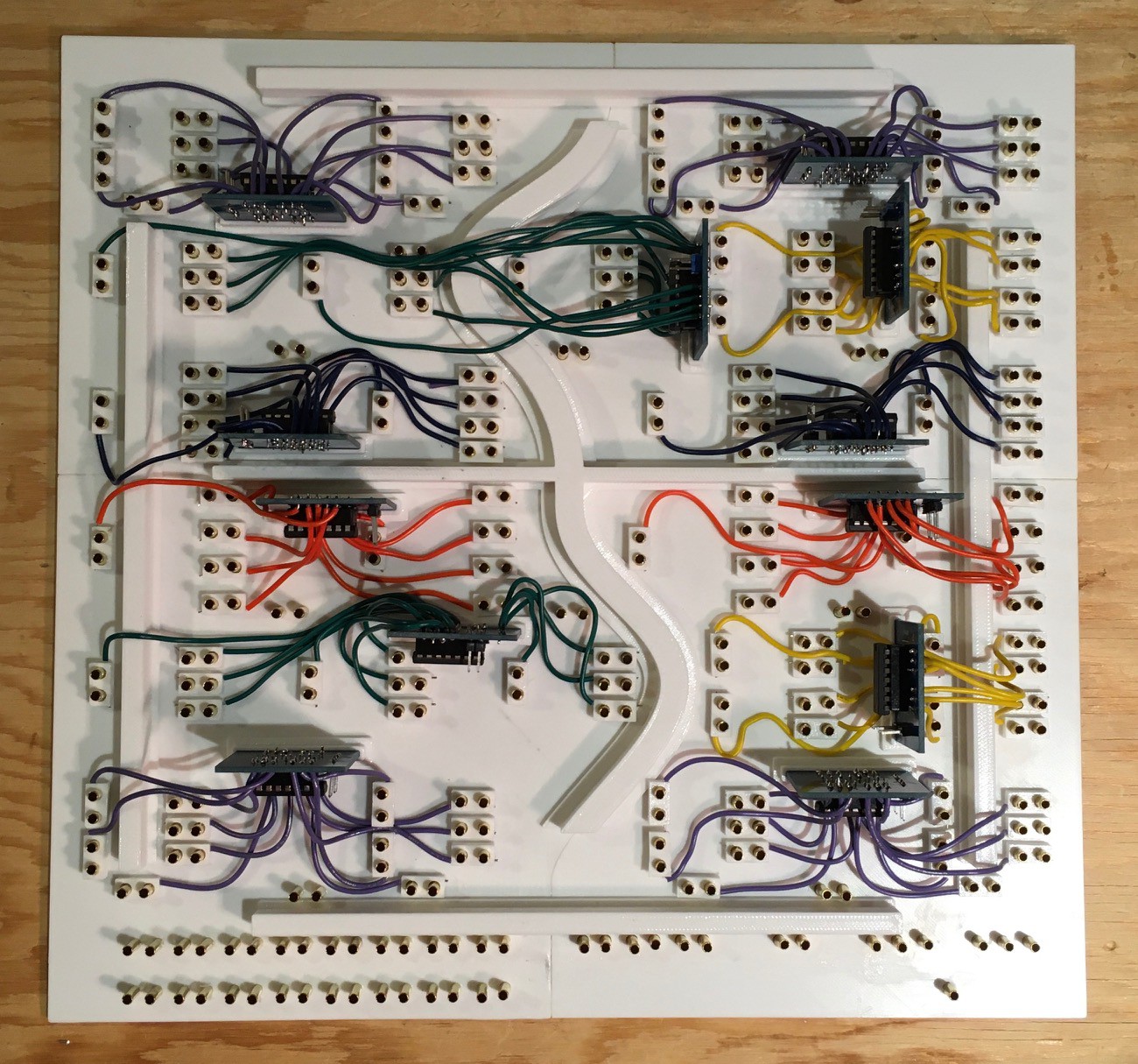
And here you go. All the logic elements are now wired except for power which I'll run when I put all of the pieces together. Next I'll knock together a frame to mount everything in.
Framing
If I had access to my local maker-space (kwartzlab) I probably would have ripped something down to the required 1/2" x 3 1/4" board size that I needed, but I was "lucky" enough to find some "craft board" at Lowes in the required size.
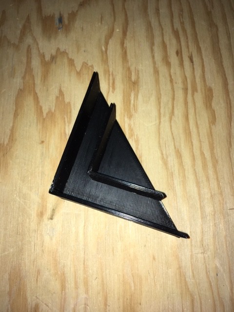
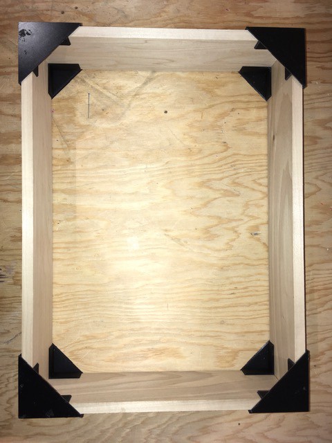
The other maker-space thing that I missed was access to their fine selection of corner clamps to put the frame together, so I had to improvise. I ended up printing some corner guides that worked quite well.
I mitered the corners of the frame and used the guides to align the boards while I glued and popped in a few brads.
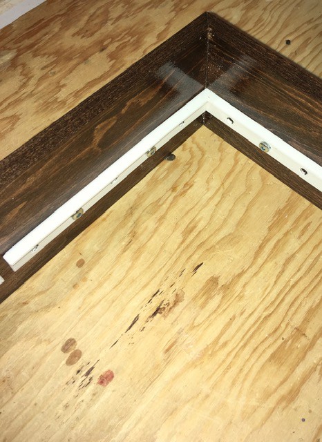
 Once dry I stained the boards then applied a few applications of clear coat. I was a little disappointed in the stain as I was expecting it to be a little lighter and redder like the original's "simulated teak". But given how long it took to get the stain I went ahead and used it.
I printed some supports to hold the Plug, Light, and Switch Panels in place at their appropriate depths (1/2" for the Switch Panel and 1 3/4" for the Plug Panel) within the frame and attached them to the inside faces with 1/2" wood screws.

I attached the panels onto the frame supports with some E6000 Adhesive.
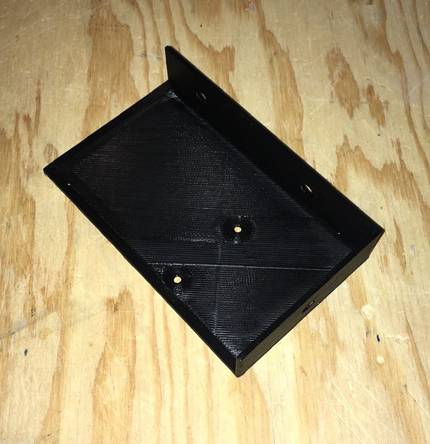
Finally I printed a mount for the Arduino Mega...
...and installed it in the corner of the frame underneath the potentiometer.
Wiring the Lower Half
The first thing that I noticed when I started the wiring was that the switch assembly wires (purple) and the light panel LEDs (grey hexes) were overlapping, making my life harder than it had to be.
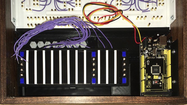
So I removed the switch assembly and rebuilt it, moving the eight brown rocker switch wires to the bottom of the assembly (the pulse switches were OK). There is a nice channel on that side to run the wires between the frame and the assembly itself. Following this wiring diagram...

...it was pretty clear sailing and here is the result:
For reference the wire colors are:
- purple - switch inputs to Arduino
- grey - switch outputs from Arduino
- white - clock out and clock delay control from and to Arduino
- yellow - potentiometer input to Arduino
- red - power +, 9V to Arduino, 5V from Arduino
- black - ground
The LEDs are wired directly to the lamp inputs with a 4K limiting resistor (large enough to keep the brightness down to incandescent levels). While wiring the LEDs I noticed a pretty big goof on my part. The label for the lamp terminals should have read LAMP INPUTS. Doh!

Oh well nothing to do about it now. I have updated the patch panel STL file but will live with my error on this build.
Wiring the Upper Half Power
Running power to the breakout boards was relatively straight forward. Each PCB has a 2-pin header for both VCC and GND.
Starting from the 5V and ground outputs on the Arduino, I made cables to length with single female header ends, and used these to "daisy chain" the power and ground from one PCB to the next until all twelve were connected. Occasionally a power or ground cable was tapped off of these to power the HIGH and GND terminals.

Wiring complete!
Patch Cables
With the H-500 pretty much ready to go, I started making the patch cables.
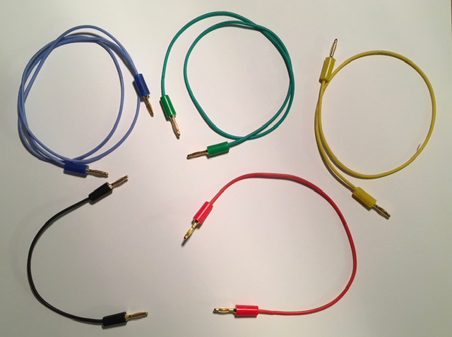
I found some relatively inexpensive 2 mm banana plugs at about 56 cents CDN each. The wire insulation is silicon based and very flexible. From Amazon:
- 22 Gauge Electric Wire,Tinned Copper Wire Kit 22 AWG Flexible Silicone Wire(6 Different Colored 26 Feet spools) 600V Electronic Hook up Wire
- 20PCS Gold Plated Banana Plug for Speaker Wire, Home Theater, Wall Plates and More(Five Colors Choices) x 5
The cables are colored coded by length and are based on the original H-500's except black was substituted for brown and there are no orange cables. Here is what the original cables looked like (from http://www.so-much-stuff.com/pdp8/computerlab/computerlab.php):
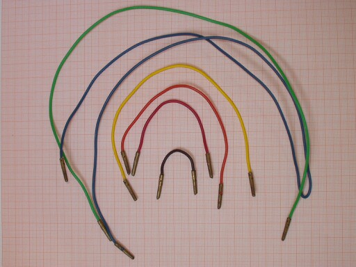
And here are the plugs that were used. If anyone knows what this type of plug is called and where one might find a supply I would be eternally grateful.
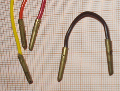
As I stated before the 2 mm banana plugs I'm using work great with the rivets so I'm fine with them for now.
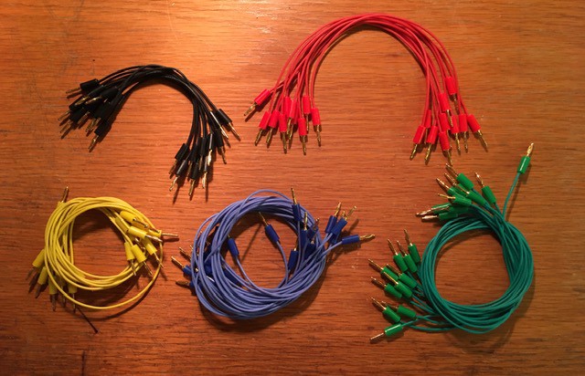
Starting with 50 cables.
Credit Where Credit Is Due, Eh
For me this is a very important part for the build.

On the back of each Computer Lab sold was a plaque with the model and serial number as seen above. What's important to me as a proud Canadian is that so far as I can determine all H-500s were Made In Canada. So I had to make sure that my reproduction had such a plaque.

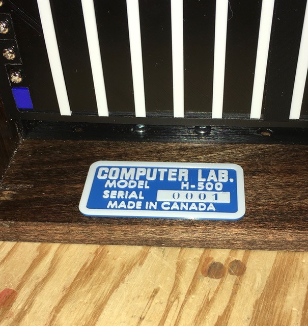
I've decided not to put a back on this project, so I mounted the plaque on the inside of the frame. I think I'm done. Ready to go!
Testing
I fired up the H-500 with a 9V 2A power supply that I got from Amazon (Haitronic 9V 2A AC/DC Power Adapter wall charger for Arduino, Center Positive 5.5mm x 2.1mm Power Supply Cord). When I saw that there were no sparks, smoke, or flames I successfully tested each of the basic logic circuits in turn using the rocker switches and "lamps". Then I tried one of the "Experiments" from the book, a "Decimal to Binary Encoder".
It worked great.
Finally I used all eight flip-flops to create a binary counter. Here is a video of the result in action. It demonstrates the use of the clock knob to power on the H-500 and control the clock rate from about 1 to 10 clocks/second. A Pulse switch is used at one point to reset the count.
Final Thoughts
It feel like this build took a really long time, but in fact it has only been three months since I started this project. There were frustrating part delivery delays due to Covid-19, and not having access to my local maker space slowed me down a bit and forced me to get creative, but all things considered I'm OK with how it went. It was nice to have something interesting to work on during this enforced "quiet time".
Now that this project is done I'm looking forward to assembling oscarv's wonderful PiDP 8/I. I think the H-500 and PiDP 8/I will look great together on my shelves.
Mike