 Michael Gardi
Patch Cables
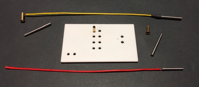
My taper pin and rivet samples arrived this week.
So I ran a few test.
The taper pins slide into the rivets easily and hold securely in part because the pins have extremely fine circular ribs along their length. They only go in about 5 mm before stopping though. I would have like for them to sink a little deeper but they work.
I ensured that the panel holes for the pivots were the right size. As it is, it takes a bit of an effort to push the rivet through the hole, but I end up with a secure friction fit that I hope will be enough without having to apply any glue.
I tried soldering a jumper wire to one of the steel taper pins. It turns that it is reasonably easy to make a nice solid connection. On top of that I plan to add some thick shrink tubing for extra support.
The 30 mm taper pins I ordered seemed a little large so I cut one down to 20 mm and it felt better to me. I can order these pins at the 20 mm length.
I did a quick check to see how hard it would be to solder to side of one of the rivets. As expected since they are brass this can be done pretty quickly which is important so as not to heat up the plastic panel too much when making the connection.
So all in all I feel that I have a viable patch cable solution. Before I order the tapers though I am going to try some 2 mm banana plugs that I think might work a bit better. Samples ordered.
Toggle Switches
I also received some "light brown" AMZ3D filament that I though might be a good fit for the 8 input switches. Before printing some test switches I split the STL file into two parts to avoid having to use supports.
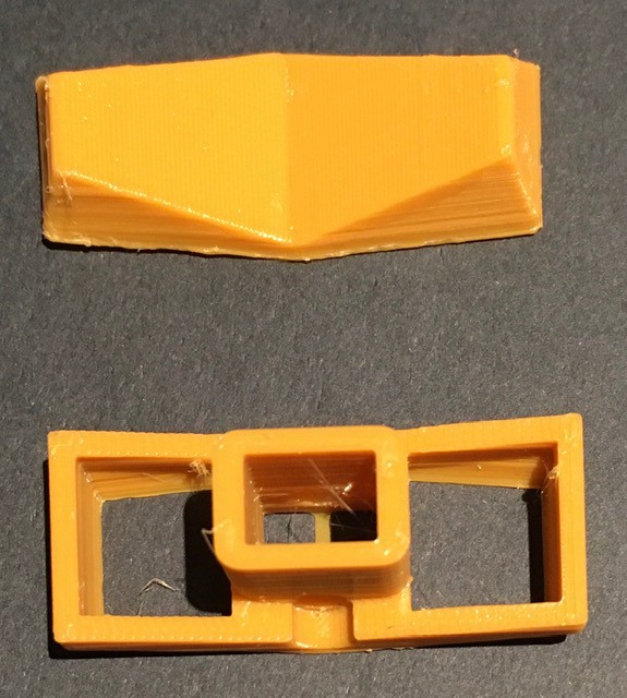
I'd rather spend a few seconds gluing then 10 minutes removing support material. You end up with a small seam (where it will never been seen) but with a much cleaner print.
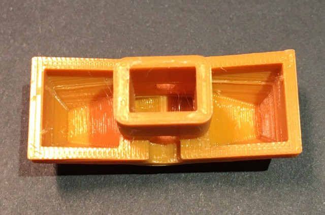
These pictures appear way too yellow and do not do justice to the actual color which has a nice caramel/butterscotch look to it. It's certainly in the ballpark based on pictures of H-500s that I have seen online.
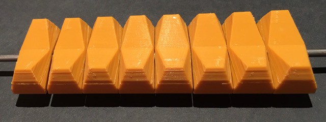
Now I don't have an H-500 to compare with, but I have ordered one of Oscarv's awesome PiDP-8/I replicas. I know that he has gone to some lengths to get the toggle switch colors right so I'll have a better example to compare with.
Next Steps
Now that I feel like I have mitigated any risks it's time to move forward. Laying out the front panels and printing them is next on my agenda.
Discussions
Become a Hackaday.io Member
Create an account to leave a comment. Already have an account? Log In.
Have you thought about using a PCB, and the cheap jumpers used on solder less breadboards [that have pins on the ends]? and real receptacles that are meant for wires / pins? I use a PCB house that builds 2 sided boards up to 60 sq in for $30 in sets of 3 or more, and Mill-Max receptacles # ED90580 from Digikey are about $.10 each if you order 250 & up. It seems to me you could scale the board dimensions so that 60 sq in would be workable.
Are you sure? yes | no