 Michael Gardi
Well I've started to wire up the Plug Panel. The circuits represented by logic symbols on the top of the board are implemented with a dozen 7400 series ICs underneath.

By looking at the logic symbols and using pictures of the wiring for the original H-500 I was able to determine the chips used:
- SN7400 - 2 Quadruple 2-Input Positive-NAND Gates
- SN7410 - 2 Triple 3-Input Positive-NAND Gates
- SN7420 - 2 Dual 4-Input Positive-NAND Gates
- SN7450 - 2 Dual AND-OR-Invert Gates
- SN7473 - 4 Dual J-K Flip-Flops with Clear
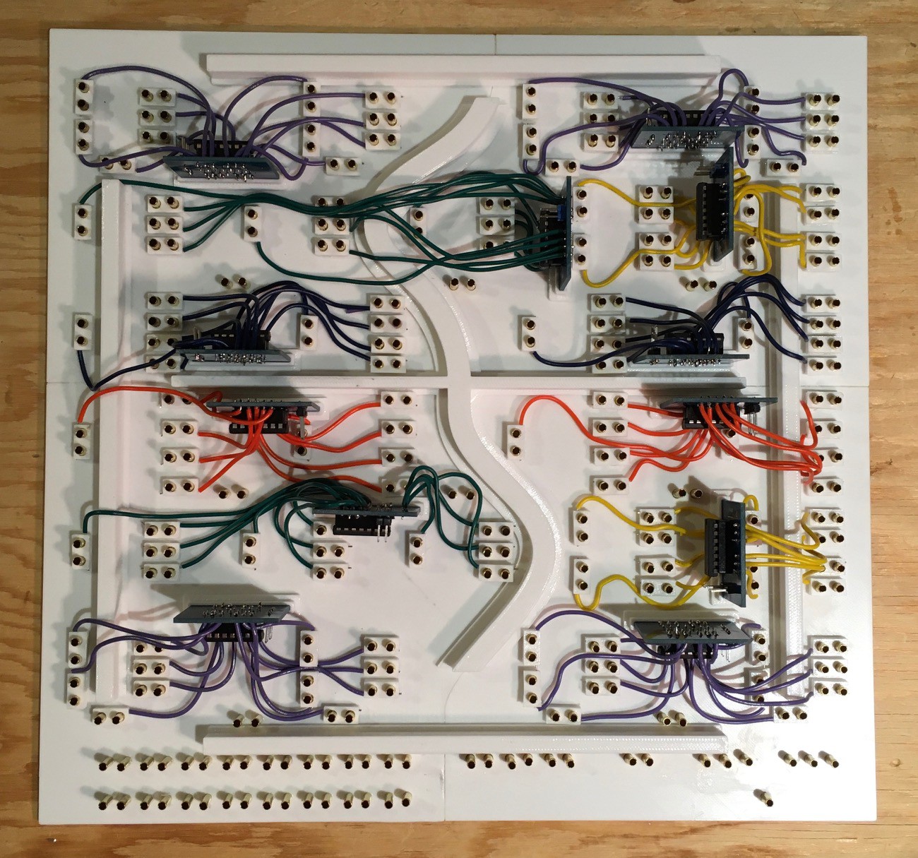
So this is what I have so far:
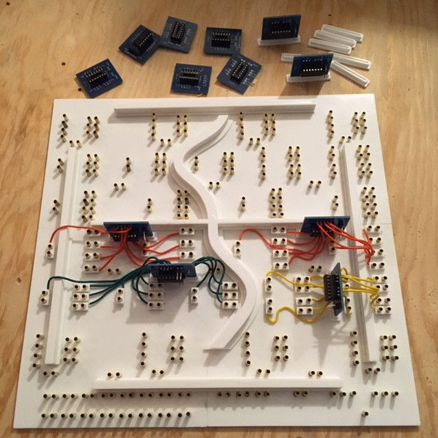
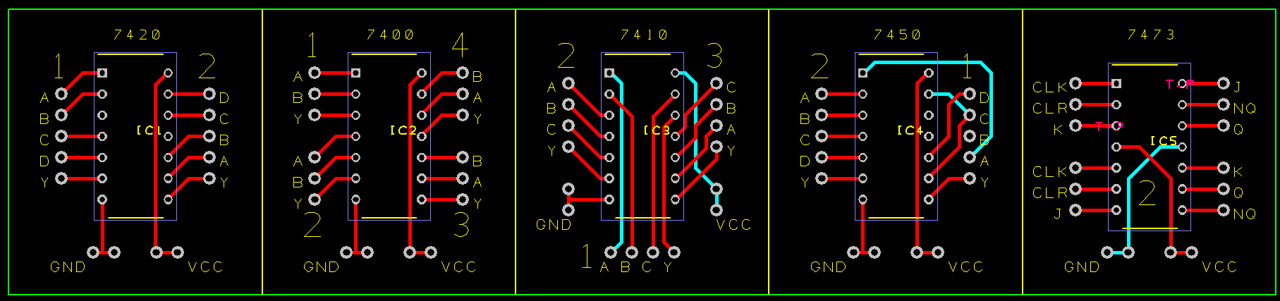
There's a few things to note here. First of all I decided to make my life a little easier by creating some breakout boards for the 74XX chips. My initial though was to just "dead-bug" the chips and solder the leads directly to the pins. It would have worked but the appeal of re-arranging the pin-outs to be more consistent with the layout of the panel, plus having a label on each pin won out. Here's the PCB:
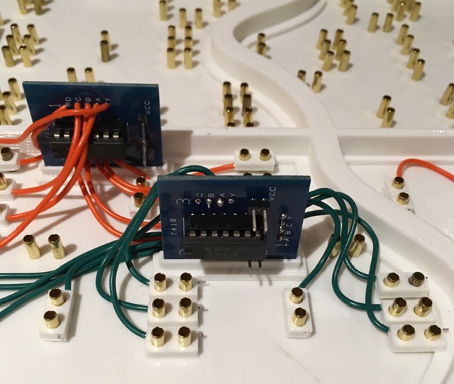
I created a small base for the PCBs so that I could stand them upright since there was no room to lay them out.
My plan was to solder the wires coming from the break-out boards directly to the brass rivets. It turned out that this was a lot harder than I thought it would be. I really should have tested this much earlier in the process. I don't know if the brass was coated with something but the soldering iron had to be applied to the rivets way too long to get a good join. As a result the panel holes melted and got too large to hold the rivet securely in place. I needed a plan B.
They say the necessity is the mother of invention, and I think the solution I came up with is actually better than if the soldering had worked. I made some mechanical "fittings" to securely attach the wires to the rivets:
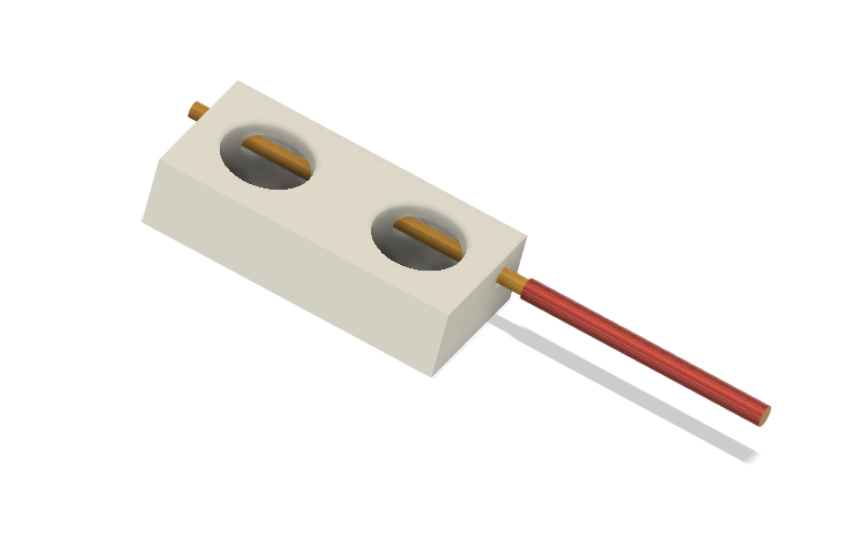
Just insert the wire into the horizontal hole and slide the fitting over a pair of rivets representing a circuit lead. These work great, are quick and easy to install, and actually reinforce the rivet's attachment to the panel. An additional benefit is that a whole PCB "circuit" can be removed from the panel should the need arise to troubleshoot. Here's a closer look.
So with the bugs ironed out, it's time to finish the Plug Panel wiring.
And here you go. All the logic elements are now wired except for power which I'll run when I put all of the pieces together. Next I'll knock together a frame to mount everything in.
Discussions
Become a Hackaday.io Member
Create an account to leave a comment. Already have an account? Log In.